Transcript
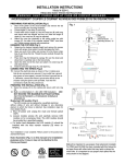
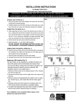
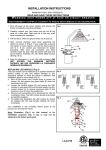
INSTALLATION INSTRUCTIONS
For Model 72414-51A-L
W A R N I N G ! S H U T P O W E R O F F AT F U S E O R C I R C U I T B R E A K E R .
AVERTISSEMENT! COUPER LE COURANT AU NIVEAU DES FUSIBLES OU DU DISJONCTEUR.
PREPARING FOR INSTALLATION (Fig. 1)
1. Shut off the power at the circuit breaker and remove the old fixture,
including the mounting hardware. Carefully unpack your new fixture
and lay out all the parts on a clear area. Take care not to lose any
small parts necessary for installation.
2. Attach the cage to roof (J) with cap nuts (S).
3. Thread nipple (E) into loop (G) until snug and secure with lock
washer (D) and hex nut (C). Attach the crossbar assembly to the
outlet box with screws (B). The side of the cross bar marked “GND”
must face out.
4. Use a pair of proper pliers to open one end link of the chain provided
and connect to the fixture loop (I). Determine the desired hanging
height and discard the excess chain.
5. Lace the fixture wires through the chain. Slip lock collar (H) over the
chain followed by canopy (F) and allow them to rest on the fixture top
cover.
6. Open the other end link of chain and attach to loop (G). Feed the
fixture wires through the loop (G) and the nipples (E).
CONNECTING THE WIRES (Fig. 2)
7. Connect the electrical wires as shown in Fig.2.Making sure that all
wire connectors are secured. If your outlet box has a ground wire
(green or bare copper), connect the fixture’s ground wire to it.
Otherwise, connect the fixture’s ground wire directly to the crossbar
using the green screw provided.
COMPLETING THE INSTALLATION (Fig. 1)
8. Align canopy (F) to the ceiling and use lock collar (H) to secure
canopy (F) to chain loop (G).
8. Bulb (H) information: (1 x AC LED 10W included.)
DO NOT EXCEED THE MAXIMUM WATTAGE RATING! (NE PAS
DEPASSER LA PUISSANCE NOMINALE MAXIMALE!)
Fig. 1
Fig. 2
FIXTURE
WIRES
Black or
Smooth
FIXTURE
WIRES
White or
Ribbed
HOUSE
WIRES
Black
(Hot)
FIXTURE
WIRES
Bare
Copper
(Ground)
HOUSE
WIRES
White
(Neutral)
HOUSE
WIRES
Green or
Bare
Copper(
Ground)
Replacing LED module (Fig. 4)
The LED module can be replaced by a qualified electrician without
cutting of wire and without damage to any decorative element to which
the fixture is attached. See installation steps for more details (Fig 4.)
a. Remove top cover (J) by loosening cap nuts (S) (Fig.1), then
remove aluminum cover (O) by loosening screws (K).
b. Remove the wire nuts (L) hex-nuts (N) washers (M) and carefully
remove the LED module (Q) for re-lamping. Note: The LED module
should be provided by a specified supplier.
c. For better heat dissipation the LED module (Q) should be installed
with the heat transfer material (P) when re-lamping
.
Your installation is now complete. Return power to the junction
box and test the fixture
Fig. 3
Caulking
Backplate
Fig. 4
O
K
P(Graphite sheet)
Q(LED module)
T (Module ring)