1
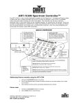
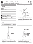
REMOTE CONTROLLER INSTALLATION INSTRUCTION
IMPORTANT NOTE:
1.) You must set ceiling fan manual switch to high speed and light kit (if any) to on position before
operating remote control.
2.) Read and save these instructions.
3.) Please note that all-fixed wiring appliances should be installed by a qualified electrician.
4.) The supply to the remote control receiver should be connected through a mains switch, i.e. existing
wall switch.
5.) Before installing Remote Controller, make sure the Main Power Supply is turned off.
6.) Install receiver into the ceiling fan canopy of the fan to ensure proper protection.
7.) Electric Rating: AC120V, Light: 300W (Max), Fan: 1.25A (Max).
8.) Do not install in damp locations or immerse into water. (For indoor use only.)
9.) Do not install in Tungsten Light kit, only for the Energy saving bulb.
10.) Do not pull on or cut leads shorter.
11.) Do not drop or bump the unit.
12.) The Battery will weaken with age and should be replaced before leaking takes place as this will
damage the transmitter. Dispose of used battery properly. Keep the battery out of reach of children.
13.) CAUTION: To reduce the risk of fire or injury, do not use this product in conjunction with any
variable(rheostat) wall control.
SET CODE SWITCH BETWEEN TRANSMITTER AND RECEIVER:
There is a code switch in transmitter and
receiver (See Fig.1). First. Set all of the 4
keys at "ON" position. If more than one
remote controlled fan is installed or the code
interfered, the fan may function abnormally.
In this situation, you need to reset the fan code
switch as per following instructions.
Please use a ball pen (or any convenient tool) to
poke keys to select a desired code mode which
will not interfere with other electrical units. There
are 15 code modes for selection excluding the
original ex-factory mode. (See Fig.2)
*** Please note to change the code switches in the
transmitter & receiver at the same time & at the
same key position.***
ON DIP
Key
"OFF" position
CODE SWITCH
(Ex-Factory Mode)
1
2
3
4
1
2
When 2 keys are in "OFF" position.
1
2
3
4
1
2
3
When 3 keys are in "OFF" position.
1
2
3
4
1
2
1
2
1
Page 1
( Fig 1.)
3 4
2
1
When 1 key is in "OFF" position.
When 4 keys are in "ON" or "OFF" position.
"ON" position
2
3
4
1
2
3
4
1
2
3
4
4
1
2
3
4
1
2
3
4
3
4
1
2
3
4
1
2
3
4
3
4
3
4
1
2
3
4
1
( Fig 2.)
2
3
4
INSTALL AND MAKE WIRE CONNECTION:
1.) Make sure the electric power was turned off.
2.) Ceiling fan must be set at HIGH speed and light kit (if any) at
ON position by pulling the "Pull Switch" after installation.
3.) Once the connection has been made, the receiver inserts into
the drop rod hanging bracket. The canopy comes up to cover
the receiver and bracket. (See Fig.3)
4.) Make Wire Connection: (See Fig.4)
a. The Motor white wire to the white "To Motor N" wire from Receiver with a wire nut.
b. The Motor black wire to the black "To Motor L" wire from Receiver with a wire nut.
c. The Motor blue wire to the blue "For Light" wire from Receiver with a wire nut.
d. The white wire from Outlet Box to the red "AC in N" wire from Receiver with a wire nut.
e. The black wire from Outlet Box to the red "AC in L" wire from Receiver with a wire nut.
Make sure all of wire nuts are connected firmly.
Tuck all wire nuts and wires carefully up into the Outlet Box, EXCEPT antenna, which should
remain outside Outlet Box.
Antenna
(Leave unconnected
and do not cut)
Receiver
e.
d.
Antenna:
DO NOT CUT
OR SPLICE
Hanger Bracket
a.
b.
VIEW AFTER INSTALLATION
c.
Hanger Ball
Fig.3
Fig.4
5.) Install a 9V battery (not included) into the transmitter. Turn on the power, press button of
transmitter to operate the fan. (See Fig.5)
Note:
6.) Functions of Transmitter. (See Fig.6)
This remote controller has memory function
HI:
Turn on the fan at high speed.
setting. The fan will operate at the same
MED:
Turn on the fan at medium speed. speed and the fan light will stay at the same
LOW:
Turn on the fan at low speed.
status as the last time the power supply was
FAN/OFF:
Turn off the fan.
turned off.
LIGHT ON/OFF:
Press and release immediately to turn on or off the light.
7.) Install the transmitter wall bracket in wall by two screws and hang transmitter in it carefully.
(See Fig.7)
TO INSTALL THE BATTERY, PRESS DOWN AND
SLIDE OUT BATTERY HOUSING COVER.
Transmitter
FAN/OFF
LIGHT
ON/OFF
Battery Housing
Cover
LIGHT
ON/OFF
HI
HI
MED
LOW
Battery 9V
Fig.5
FA N / O F F
Wall Bracket
MED
LOW
Screw
TRANSMITTER
Fig.6
Page 2
Fig.7