Transcript
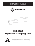
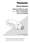
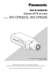
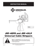
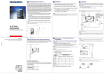
Installation Instructions
BULB REPLACEMENT INSTRUCTIONS
See the label on the fixture for replacement bulb type
information. Do not replace with any other wattage of
fluorescent bulb.
1) Turn the fixture off and allow bulb to cool before handling.
2) Remove the lens/diffuser by lightly pulling the rear
edge towards the front and down. The lens/diffuser should
pop out easily. See Figure 1.
3) Remove the bulb by grasping the ends of the bulb and
rotating until the bulb becomes loose. Pull straight out
from the lamp holder. Be careful not to drop the bulb.
WARNING
Risk of electric shock
-
Do not use in wet locations.
Use indoors only.
Turn power off before servicing -- see instructions.
Properly ground fixture.
Ensure that no bare wires are exposed outside the
electrical connections.
Bulb may shatter and cause injury if broken
- Do not use excessive force when installing bulb.
INSTALLATION PROCEDURES
1) Consult a local licensed electrician or electrical
contractor if you are not sure about the installation.
2) Ensure that electricity is TURNED OFF at the main
circuit breaker or fuse box. DO NOT ATTEMPT TO
INSTALL FIXTURE WITH THE POWER ON.
3) Select a suitable dry mounting location (for indoor
use only). Make sure the mounting surface is capable
of supporting the fixture.
4) Remove the lens/diffuser by lightly pulling the rear
edge towards the front and down. The lens/diffuser should
pop out easily. See Figure 1.
5) Remove the bulb by grasping the ends of the bulb and
rotating until the bulb becomes loose. Pull straight out
from the lamp holder and remove any cardboard inserts
present. Be careful not to drop the bulb. See Figure 1.
6) Remove the cover/housing by unscrewing the nuts located
behind the bulb. Some models have screws located on the top
and bottom of the fixture that hold the cover/housing together.
7) Choose a suitable knock-out location from those provided
on the fixture. Remove the knock-out with a screw driver.
8) Insert the threaded end of the strain relief (provided in the
installation kit) into the selected opening on the fixture.
Secure the strain relief by tightening the lock nut. The lock
nut should be tightened with a tool such as a pair of pliers to
ensure the strain relief is properly grounded to the fixture.
9) Install the wire to meet electrical codes.
Tighten the two screws on the strain relief connector to
secure the wires. Make sure wire insulation is stripped as
follows:
Solid wire and 7 strands or less: 5/16”
Stranded wire: 3/8”
Combinations involving 14AWG: 5/16”, 20 and
22AWG:1/2”
10) Connect the hot (black) AC supply wire(s) to the hot (black)
wire(s) of the fixture. Secure the connection with the wire
nuts provided. See Figure 2.
11) Connect the white (neutral) AC supply wire(s) to the neutral
(white) wire(s) of the fixture. Secure the connection with the
wire nuts provided. See Figure 2.
12) Connect the ground (green or copper) AC supply wire to the
green or copper ground wire of the fixture. Secure the
connection with the wire nuts provided. If your electrical
system contains no grounding wire, you should consult a
qualified electrician before proceeding with the installation.
See Figure 2.
13) Ensure that no bare wires are exposed after making the
electrical connections.
14) Arrange the wires inside the fixture and reattach the
cover/housing. Tighten the screws or nuts to ensure that all
the wires and connections are sealed properly inside the
fixture without "pinching" any wires.
15) Place the fixture in the location where it is to be mounted
and mark the position of the keyholes with a pencil.
16) It is recommended that a 1/16" pilot hole be drilled in the
mounting surface.
Risk of burn
- Allow bulb to cool before handling.
Risk of fire
- Not intended for illumination of aquariums.
See Figure 1.
4) Grasp the replacement bulb in the same manner
and reinsert into the lamp socket and turn tube until
it is securely held in place. Do not use excessive force
when installing bulb.
- Not intended for recessed installation in
ceilings or soffits.
- Not intended for surface installation inside
built-in furnishings such as kitchen cabinets,
china cabinets, or trophy cases.
17) Drive the screws provided in the mounting hardware into the
mounting surface until approximately 1/8" of space remains
under the head of the screw. See Figure 3.18) Align the keyholes
in the fixture with the two screws
and slide into place. See Figure 4.
19) Tighten the screws and install bulb and reinsert lens.
20) Turn on the electricity at the circuit breaker or fuse box.
Figure 1 / Figura 1
Rear
Lens/Diffuser
Edge
Lente/difusor
(borde frontal)
Jasco Products Company LLC,
10 E. Memorial Rd., Oklahoma City, OK 73114.
www.jascoproducts.com.
UCF003 ES
Consulte en la etiqueta del artefacto la información sobre
el tipo de bombilla de reemplazo. No la reemplace con una
bombilla de ningún otro voltaje o fluorescente.
1) Apague el artefacto y espere a que la bombilla se enfríe
antes de manipularla.
2) Retire la lente/difusor tirando la orilla trasera hacia la frente y
abajo.
3) Para retirar la bombilla, tómela de los extremos y hágala
girar hasta que se suelte. Retírela en forma recta del
portalámparas. Asegúrese de no dejar caer la bombilla.
Vea la Figura 1.
4) Tome la bombilla de reemplazo del mismo modo e insértela
nuevamente en el portalámparas y hágala girar hasta que
calce con seguridad en su lugar. No ejerza fuerza excesiva
cuando instale la bombilla.
ADVERTENCIA
Riesgo de choque eléctrico
- No use en lugares húmedos.
- Use sólo en interiores.
- Desconecte la alimentación antes de realizar
tareas de servicio - consulte las instrucciones.
- Conecte el artefacto a tierra de manera apropiada.
- Asegúrese de que no haya cables descubiertos
expuestos fuera de las conexiones eléctricas.
La bombilla se puede hacer añicos y
causar lesiones si se rompe
- No ejerza fuerza excesiva cuando instale la bombilla.
Riesgo de quemaduras
- No utilize la luminária para iluminar peceras.
- No instale la luminária en el techo.
- No instale la luminária dentro de los gabinetes
u otra estructura permanente.
PROCEDIMIENTOS DE INSTALACIÓN
1) Consulte a un electricista o contratista de servicios eléctricos local
matriculado si usted no está seguro acerca de la instalación.
2) Asegúrese de que la electricidad esté DESCONECTADA en el
disyuntor o caja de fusibles principal. NO INTENTE INSTALAR
Cubierta /
EL ARTEFACTO CON LA CORRIENTE CONECTADA.
Carcasa
3) Seleccione un lugar de montaje seco adecuado (sólo para
Figure 2 / Figura 2
uso en interiores). Asegúrese de que la superficie de montaje
pueda soportar el artefacto.
4) Retire la lente/difusor tirando la orilla trasera hacia la frente y
AC Supply Wires /
abajo.
Cables de Alimentación
Strain Relief /
de CA
5) Para retirar la bombilla, tómela de los extremos y hágala girar
Sujetacables
hasta que se suelte. Retírela en forma recta del portalámparas
y remueva cualquier cartón que este presente. Asegúrese de
Hot (Black) Supply Wire
no dejar caer la bombilla. Vea la Figura 1.
Cable de Alimentación
6) Para retirar la cubierta/carcasa, desatornille las tuercas
Ground (Green or
Vivo (Negro)
situadas detrás de la lámpara. Algunos modelos tienen tornillos
Copper) Wires
que sostienen la cubierta/carcasa en las partes superior e inferior
Cables de Conexión
del artefacto.
a Tierra
(Verde o Cobre)
7) Seleccione una ubicación de recorte en las provistas en
el artefacto. Retire el recorte con un destornillador.
Neutral (White) Supply Wire
8) Inserte el extremo roscado del sujetacables (provisto con
Cable de Alimentación
el equipo de instalación) en la abertura seleccionada del
Neutro (Blanco)
artefacto. Para asegurar el sujetacables, apriete la tuerca
de retención. La tuerca de retención se debe apretar con
Neutral
(White)
Hot (Black)
una herramienta tal como una pinza a fin de asegurar que
Fixture Wire
Fixture Wire
el sujetacables esté conectado al artefacto correctamente.
Cable Neutro (Blanco)
Cable Vivo (Negro)
9) Instale el conducto para cable o el cable blindado según
del Artefacto
del Artefacto
los códigos de electricidad. Apriete los dos tornillos del
conector del sujetacables para asegurar los cables. Asegúrese que
Figure 4 / Figura 4
Figure 3 / Figura 3
el aislamiento haya sido desforrado en la siguiente manera:
Conductor sólido o de 7 hebras o menos: 5/16”
Conductor trenzado: 3/8”
Combinaciones incluyendo 14AWG: 5/16”, 20 y
22AWG: 1/2”
10) Conecte el cable de alimentación de CA vivo (negro) al
3,1
cable vivo (negro) del artefacto. Asegure la conexión con
mm
las tuercas aisladoras para cables provistas. Vea la Figura 2.
11) Conecte el cable de alimentación de CA blanco (neutro) al
is a trademark of the General Electric Company
cable neutro (blanco) del artefacto. Asegure la conexión con
and is used under license to
las tuercas aisladoras para cables provistas. Vea la Figura 2.
Cover /
Housing
INSTRUCCIONES DE REEMPLAZO
DE LA BOMBILLA
12) Conecte el cable de conexión a tierra de CA (verde o cobre)
al cable de conexión a tierra color verde o cobre del artefacto.
Asegure la conexión con las tuercas aisladoras para cables
provistas. Si su sistema eléctrico no incluye un cable de
conexión a tierra, debe consultar a un electricista calificado
antes de proceder a la instalación. Vea la Figura 2.13) Asegúrese de
que no haya cables descubiertos expuestos
después de realizar las conexiones eléctricas.
14) Disponga los cables dentro del artefacto y coloque
nuevamente la cubierta/carcasa. Ajuste los tornillos o tuercas a
fin de asegurarse de que todos los cables y conexiones estén
apropiadamente sellados dentro del artefacto, sin pinzar los
cables.
15) Coloque el artefacto en el lugar donde lo montará y marque
la posición de los orificios de guía con un lápiz.
16) Se recomienda perforar un orificio piloto de 1,5 mm en la
superficie de montaje.
17) Inserte los tornillos provistos con los elementos de montaje
en la superficie de montaje hasta que quede un espacio de
aproximadamente 3,5 mm debajo de la cabeza del tornillo.
Vea la Figura 3.
18) Alinee los orificios de guía del artefacto con los dos tornillos
y deslícelo hasta que calce en su lugar. Vea la Figura 4.
19) Apriete los tornillos, instale la bombilla y vuelva a insertar
la lente.
20) Conecte la electricidad en el disyuntor o la caja de fusibles.
2/28/2007
10113
16028
16687
10142
10143