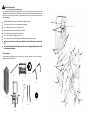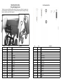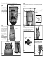
1
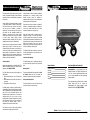
Manufacture’s Limited Warranty for
Owner’s Manual | LC2000|
The limited warranty set forth below is given by Precision
Products, Incorporated with respect to new merchandise
purchased and used in the United States, its possessions
and territories.
Precision Products Inc. Will not be liable for incidental or
consequential loss or damage including, without
limitation, expenses incurred for substitute or
replacement lawn care services, or for rental expenses to
temporarily replace a warranted product.
Precision Products, Incorporated warranties the product
(s) listed against defects in material and workmanship,
and will at our option, repair or replace, free of charge,
any part found to be defective in materials or
workmanship. This limited warranty shall only apply if
this product has been assembled, operated, and
maintained in accordance with the owner’s manual
furnished with the product, and has not been subjected
to misuse, abuse, neglect, accident, improper
maintenance, alteration, vandalism, theft, fire, water, or
damage because of other peril or natural disaster.
Some states do not allow the exclusion of limitation of
incidental or consequential damages, or limitations on
how long an implied warranty lasts, so the above
exclusions or limitations may not apply to you.
During the warranty period, the exclusive remedy is
replacement of the part. In no event shall recovery of
any kind be greater than the amount of the purchase
price the product sold. Alteration of safety features of the
product shall void this warranty. You assume the risk and
liability for loss, damage, or injury to you and your
property and/or to others and their property arising from
the misuse or inability to use this product.
Normal wear parts or components thereof are subject to
separate terms as follows: All normal wear parts or
component failures will be covered on the product for a
period of one year. Parts found to be defective within the
warranty period will be replaced at our expense. Our
obligation under this warranty is expressly limited to the
replacement or repair, at our option, of parts found to be
defective in material and workmanship.
This limited warranty shall not extend to anyone other
than the original purchaser or to the person for whom it
was purchased as a gift.
Local Law to this Warranty
Contacting Service
This limited warranty gives you specific legal rights, and
you may also have other rights which vary from state to
state.
Warranty parts replacements are available, ONLY WITH
PROOF OF PURCHASE, through our Customer Service
Department. Call 1 (800) 225-5891
Warranty Period
The Warranty period stated below begins with the Proof
of Purchase. Without the proof of purchase, the
Warranty period begins from the date of manufacture.
This limited warranty does not provide coverage in the
following cases:
1. Routine maintenance items such as lubricants and
filters.
2. Normal deterioration of the exterior finish due to use
or exposure.
3. Transportation and/or labor charges.
Dump Cart Warranty Period
The warranty period for this unit is as follows: All parts
are covered one year from the date of sale.
No implied warranty, including any implied warranty of
merchantability of fitness for a particular purpose, applies
after the applicable period of expressed written warranty
above as to the part as identified below. No other
expressed warranty whether written or oral, except as
mentioned above, given by any person or entity,
including a dealer or retailer, with respect to any product,
shall bind Precision Products, Inc. During the period of
the warranty, the exclusive remedy is repair or
replacement of the product as set forth above.
The provisions as set forth in this warranty provide the
sole and exclusive remedy arising from the sale.
Manual Contents
Safety Instructions
Assembly
Operation
Maintenance
Parts
Warranty
Your New Mighty Yard Garden Cart
2
4-6
6
6
3
8
Congratulations on your purchase of a new
Precision Products, Inc. Mighty Yard Garden Cart.
Your Cart has been engineered and built to give
you the most dependable and best performing
product possible.
If you experience any problem you can not easily
resolve, please feel free to contact our
knowledgeable and helpful customer service
department toll-free at 1 (800) 225-5891.
Caution: Carefully read all rules and instructions for safe operation.
8
(Rev. 08/12)
Rules for Safe Operation
The following safety precautions are suggested. This Cart is designed, engineered and tested to offer
reasonably safe and effective service, provided that it is operated in strict accordance with these instructions.
Failure to do so may result in personal injury. Always observe the rules of safe operation. Please read and
retain this manual.
1
Read and understand your owner’s manual and safety rules before using.
Do not allow anyone to ride or sit on equipment during operation.
3
Do not allow children to use cart. This cart is not a toy.
16
Always distribute load evenly over the surface of the bed.
Do not load anything on the edges of the plastic tray.
11
Do not use if any parts are damaged or broken.
Do not operate or use on objects that may cause damage to the pneumatic tires or tubes.
Please use a manual foot or hand pump to inflate tires. Do not inflate tires to more than 20
PSI.
Do not load Cart with more than 600 pounds. Do not use the tipping/dumping feature of the
cart more than 300 pounds.
4
11
7
Carton Contents
Before assembling the tipping cart please check all the parts and hardware, if anything is missing or
damaged, please contact the seller.
8
5
15
4
12
2
3
5
14
6
10
2
1
9
8
7
9
14
13
15
12
6
2
7
Operating Instructions
Using the tipping feature
Not Shown Actual Size
To tip the tray, press and hold the handle and tray. Lift up the tray to allow the contents to tip
out. When tipping is completed, place tray back into horizontal position ensuring the locking
handle is securely in place. Refer to figure 8.
14
12
12
15
Fig 8
11
16
10
13
Ref.
QTY.
1
1
2
Description
Ref.
QTY.
Body
1
1
Body
1
Axle
2
1
Axle
3
1
Locking Frame
3
1
Locking Frame
4
4
Wheel
4
4
Wheel
5
2
Left & Right Leg
5
2
Left & Right Leg
6
1
Frame Assembly
6
1
Frame Assembly
7
1
Handle
7
1
Handle
8
2
Cart Stiffeners
8
2
Cart Stiffeners
9
1
Handle Coupler
9
1
Handle Coupler
10
1
M8 X 60 Bolt
10
1
M8 X 60 Bolt
11
4
M8 X 25 Bolt
11
4
M8 X 25 Bolt
12
4
M12 Washer
12
4
M12 Washer
13
9
M8 Washer
13
9
M8 Washer
14
4
M12 Lock Nut
14
4
M12 Lock Nut
15
9
M8 Lock Nut
15
9
M8 Lock Nut
16
4
M8 X 20
16
4
M8 X 20
6
Description
3
Tools required for assembly: Screwdrivers, socket set and adjustable wrenches
Step 3
Step 1
Place the frame assembly onto the tray. Then place the axle through the legs and frame. Refer
to Figure 4.
Locking Frame
Place the tray upside down
and assemble the locking
frame to the tray using M8 x
20 bolts (4 pieces), washers
(4 pieces) and M8 lock nuts
(4 pieces). Refer to figure 1.
Tray
M8 X 20 Bolt,
Washers and
M8 Lock Nut
Step 4
Frame
Axle
Attach the wheels to the axles using M12
washers (4 pieces) and the M12 lock nut.
Refer to Figure 5.
Washer
Legs
Axle
Lock Nut
Wheel
Fig 1
Step 2
Turn the tray over and place
the cart stiffeners across cart
body (Figure 2) then place
left leg on top of stiffener
and secure with M8 x 25
bolt, washer and lock nut.
Repeat for right leg. Refer
to figure 3A.
Make sure long section of
tubing on legs are facing
outwards. See Fig 3B
Fig 4
Step 5
Cart Stiffeners
Place handle coupler on handle. Note there are two
options for handle position. Rotate the handle to
your desired position. Refer to figure 6.
Handle Coupler
Handle Position 1
Fig 5
Fig 2
Step 6
Attach the handle, handle coupler and
yoke using M8 x 60 Bolt, M8 lock nut
and washer. Refer to figure 7
Left & Right Leg
Handle
Handle Position 2
M8 Lock Nut & Washer
Fig 6
M8 X 25 Bolt Set
Fig 3A
M8 x 60 Bolt
Fig 3B
4
Fig 7
5