1
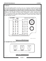
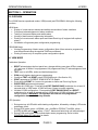
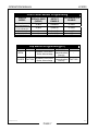
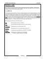
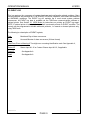
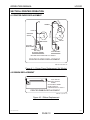
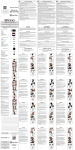
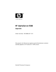
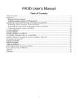
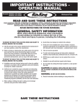
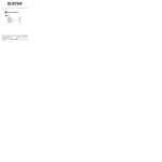
PNEUMERCATOR
LEAK/POINT
LEVEL ALARM
CONSOLE
Liquid Level Control Systems
OPERATION MANUAL
DRAWING NO. 20068 REV. N/C
MODEL LC2000
© COPYRIGHT 2007 PNEUMERCATOR CO., INC.
120 FINN COURT, FARMINGDALE, NY 11735
TEL: (631) 293-8450
FAX: (631) 293-8533
http://www.pneumercator.com
LC2000 Operation Manual.doc
09-20-07
OPERATION MANUAL
LC2000
TABLE OF CONTENTS
Section 1
1.1
1.2
1.3
1.4
Page
SYSTEM OVERVIEW
Front Panel Description...............................................................................................1
Display.........................................................................................................................2
Pushbutton Layout ......................................................................................................2
Edit Enable/Save Button .............................................................................................3
Section 2
2.1
2.2
2.3
2.4
OPERATION
View Mode...................................................................................................................4
LEDs............................................................................................................................4
Review/Program Mode ................................................................................................4
System Initialization Functions ....................................................................................5
Section 3
3.1
3.2
LOGS/REPORTS
Alarm Log ....................................................................................................................6
Event Log ....................................................................................................................7
Section 4
4.1
4.2
PRINTER OPERATION
Paper Replacement.....................................................................................................8
Ribbon Replacement ...................................................................................................8
Appendixes
A
Alarm Conditions And Code Table ..............................................................................9
OPERATION MANUAL
LC2000
WARNING
This product is wired to sensors installed in hazardous, explosive
environments. Initial application of AC power to this system should occur only
after complete verification of safe, proper installation by authorized
Pneumercator-certified service personnel. Failure to do so may result in serious
injury and/or property loss.
This manual is intended to be used for instruction on operation and basic sensor programming of
the LC2000 using it’s front panel controls, display and optional printer. Much more extensive
programming is available using the TMSComm communications software provided on CD ROM.
SECTION 1 – SYSTEM OVERVIEW
1.0 GENERAL
The LC2000 series Leak and Point Level Alarm Console offers essentially all of the sensor-related
features of the TMS series Tank Management Systems, and will interface to all of the same sensor
model types, including discriminating and non-discriminating electronic or mechanical secondary
containment leak sensors as well as single and multi-point level float sensors. All sensor inputs can
be programmed for either alarm or relay control applications, including time delay, conditional logic
and latching functions for pump/valve controls. Optional printer and numerous communications
options are also supported.
1.1 FRONT PANEL DESCRIPTION
The front panel of the LC2000 is available in four different configurations as listed below:
LC2000-1... Console without display or printer
LC2000-2... Console with display, no printer
LC2000-3... Console with display and internal printer
LC2000-4... Console with display and internal printer w/autowinder
This manual describes operational procedures pertaining to -2, -3, and -4 consoles. The LC2000-1
"Black Box" Remote Acquisition Unit is described in a separate Pneumercator document entitled
LC2000-1RAU User's manual, document #A.
As illustrated in Figure 1-1 below, the LC2000 front panel consists of an array of green, yellow and
red LED indicators for sensor status, power LED, audible alarm annunciator, ultra-bright summary
alarm LED strobe (optional), membrane pushbutton controls, security lock, and optional printer with
or without autowinder.
LC2000 Operation Manual.doc
09-20-07
PAGE 1
OPERATION MANUAL
PNEUMERCATOR
Liquid Level Control Systems
LC2000
LC 2000
NORM
LEAK/POINT LEVEL CONSOLE
PROD WATER
NORM
1
PROD WATER
9
FAULT
2
10
3
11
4
12
5
13
6
14
7
15
8
16
SENSOR NO/NC FAULT
PAPER
FEED
PRINT
PROGRAM
SENSOR NO/NC FAULT
RESET
PGM
TEST
SENSOR
SELECT
PROGRAM
SELECT
ON/OFF
DWG NO. 20078 REV. N/C
Figure 1-1 – Front Panel View
LC2000 Operation Manual.doc
09-20-07
PAGE 2
OPERATION MANUAL
LC2000
1.2 DISPLAY
The front panel display consists of an array of 4, 8, 12 or 16 groups of ultra-high intensity green,
yellow and red LED indicators for sensor state and basic configuration status, green power LED
and optional ultra-bright summary alarm LED strobe. Operating in the normal or VIEW mode,
sensor LEDs indicate NORMAL and ALARM conditions for non-discriminating sensors or NORMAL,
PRODUCT and WATER alarm conditions for discriminating sensors. Sensor and wiring FAULT
conditions are also indicated for sensors having Pneumercator’s exclusive supervised wiring
feature. The optional summary alarm flashing strobe is activated for any new alarm condition and
can be programmed to de-activate on front panel RESET, or persist until the alarm condition is
removed. See figure 1-2 below.
LC 2000
NORM
LEAK/POINT LEVEL CONSOLE
PROD WATER
NORM
PROD WATER
9
1
FAULT
2
10
3
11
4
12
5
13
6
14
7
15
8
16
SENSOR NO/NC FAULT
PROGRAM
SENSOR NO/NC FAULT
DWG NO. 20079 REV. N/C
Figure 1-2 - LC2000 LED Layout
1.3 PUSHBUTTON LAYOUT
RESET
PGM
TEST
SENSOR
SELECT
PROGRAM
SELECT
ON/OFF
DWG NO. 20076 REV. N/C
Figure 1-3 – Pushbutton Layout
LC2000 Operation Manual.doc
09-20-07
PAGE 3
OPERATION MANUAL
LC2000
1.4 EDIT ENABLE/SAVE BUTTON
DISCRIMINATING SENSOR ENABLES
(OPEN = DISABLED)
SENSOR # 1
4
8
16
12
ENABLED
DISABLED
DISCRIMINATING SENSOR ENABLES
SENSOR NO. 1 2 3 4 5 6 7 8 9 10 11 12 13 14 15 16
OPEN = DISABLED
EDIT
ENABLE / SAVE
BUTTON
PUSH UP AND
RELEASE
DWG NO. 20077 REV. A
Figure 1-4 – Edit Enable/Save Button
LC2000 Operation Manual.doc
09-20-07
PAGE 4
OPERATION MANUAL
LC2000
SECTION 2 – OPERATION
2.0 OVERVIEW
The LC2000 has two operational modes, VIEW(normal) and PROGRAM, offering the following
functions;
VIEW Mode:
• Display of current sensor statuses and audible annunciation of alarm conditions
• Front panel acknowledgement of alarm conditions
• Testing of front panel display and audible alarm
• Viewing of basic sensor programming information
• Printing of current sensor status report and Alarm/Event logs (if equipped with optional
printer)
• Initialization of logs and system configuration programming
PROGRAM Mode:
• Viewing/Programming of basic sensor configuration (Note: More extensive programming
must be performed using the supplied TMSComm software)
• Printing of sensor-only or complete system configuration reports
2.1 VIEW MODE
Pushbutton Operation:
•
•
•
•
•
•
•
•
•
RESET acknowledges the front panel horn, changes blinking new alarm LEDs to steady
“on” and turns off strobe if so programmed. All programmed relay FP acknowledges are also
activated.
TEST turns on all LEDs, strobe and double beeps horn.
PGM (recall) displays basic sensor programming.
Combined TEST and RESET enters PROGRAM mode. (See Section 2.2)
PRINT generates a CURRENT SENSOR STATUS Report.
Press and hold PRINT for 1 second to generate an Alarm and Event Log Report.
PAPER FEED advances printer paper.
Initialize all LC2000 logs – Press and hold EDIT ENABLE/SAVE pushbutton for at least 10
seconds while in VIEW mode. LC2000 will beep 3 times to confirm operation.
Initialize LC2000 configuration – Press and hold EDIT ENABLE/SAVE and RESET
pushbuttons for at least 10 seconds while in VIEW mode. LC2000 will beep 3 times to
confirm operation. WARNING! This operation will clear all user-programmed
configuration data and set factory defaults.
LED Operation:
1. During start-up, all LEDs blink while loading configuration, followed by a display, LED strobe
and beeper check.
2. During VIEW mode, green = NORMAL, red = ALARM or PRODUCT ALARM, yellow =
WATER ALARM and red and yellow = FAULT. Alarms and faults blink until acknowledged.
3. During PGM recall mode, LEDs indicate basic sensor programming. Refer to table
PROGRAM Mode LED Indicators for details.
LC2000 Operation Manual.doc
09-20-07
PAGE 5
OPERATION MANUAL
LC2000
2.2 PROGRAM MODE
1. Enter PROGRAM mode by first pressing and holding TEST to enter DISPLAY CHECK
mode, followed by RESET (while still holding TEST). After two seconds the LC2000 will
beep twice, indicating transition to PROGRAM mode. The display will now show basic
sensor programming information as indicated by the orange lettering on the front panel.
2. Initial entry into PROGRAM mode: First SENSOR ENABLE LED blinks 3 times, then goes to
programmed state, i.e. ON for enabled, OFF for disabled.
3. Press TEST/ON-OFF to enable/disable selected item(EDIT ENABLE/SAVE button must be
pressed once after entering PROGRAM mode). If selected item is SENSOR ENABLE and
item is set to DISABLE, then all associated LEDs are turned off. See PROGRAM Mode LED
Indicators table below for programming selections.
4. Press PGM/PROGRAM SELECT until the “beep” to advance to the right to the next program
item. If the selected sensor is DISABLED, pressing PGM/PROGRAM SELECT until the
“beep” will not advance to the right, and instead, the SENSOR ENABLE LED will blink 3
times, then retain its current state, which would be OFF.
5. Press and immediately release PGM/PROGRAM SELECT (w/o beep) to recall the currently
selected LED item. Associated LED will blink 3 times and return to currently programmed
state.
6. DISCRIMINATING SENSOR mode is selected via dip switches on the back of the display
board. See FRONT PANEL SENSOR PROGRAMMING table below. IMPORTANT! Dip
switch programming of DISCRIMINATING SENSOR enables will not take affect until an
EDIT SAVE operation is performed. Also, programming DISCRIMINATING SENSOR
enables via dip switches must be enabled in the LC2000 configuration file (Factory Default).
7. Edits are saved by pressing EDIT ENABLE/SAVE button.
8. PRINT generates a SENSOR CONFIGURATION Report.
9. Press and hold PRINT for 1 second to generate a complete configuration report.
PROGRAM Mode LED Indicators
SENSOR
ENABLE
OFF - DISABLED
ON (2 Fast Blinks)
ALARM INPUT
ON (3 Slow Blinks)
RELAY CONTROL
NORMALLY
OPEN/CLOSED
(NO/NC)
FAULT DETECT
ENABLE
OFF - NC
OFF - DISABLED
ON - NO
ON - ENABLED
LC2000 Operation Manual.doc
09-20-07
PAGE 6
OPERATION MANUAL
LC2000
Front Panel Sensor Programming
SENSOR
MODEL
NORMALLY
OPEN/CLOSED
(NO/NC)
FAULT
DETECT
ENABLE
DISCRIMINATION
ENABLE
As Built
DISABLED
CLOSED
As Built
ENABLED
CLOSED
NO
NO
NC
ENABLED
ENABLED
DISABLED
CLOSED
OPEN
OPEN
All Float Switches
w/o Fault Detection
All Float Switches
w/ Fault Detection
ES825-100F
ES825-200F
HS100 Series
Dip Switch Programming(S1)
S1-1
S1-2
S1-3
S1-4
ENABLE
ENABLE Front Panel
Communications
OPEN
Strobe Acknowledge
Security
DISABLE
DISABLE Front Panel
CLOSED FACTORY
Communications FACTORY
Strobe Acknowledge
Security
LC2000 Operation Manual.doc
09-20-07
PAGE 7
OPERATION MANUAL
LC2000
SECTION 3 – LOGS
The LC2000 can log the occurrence of various alarm and system error conditions. These logs are
stored in battery-backed memory for retrieval using TMSComm, and additionally can be manually or
automatically printed with optional printer installed.
3.1 ALARM LOG
This log captures the occurrence of alarm conditions based on sensor and non-hazardous contact
closure inputs programmed as alarm inputs. Inputs programmed for non-alarm functions will not be
captured. The alarm log will maintain the 24 most recent alarm occurrences. All ALARM log data is
available via the TMSComm communications software or optional printer. See Section 2.1 VIEW
Mode for instructions on printing an alarm log report. NOTE: If optional printer is included, factory
default is automatic printout on ALARM condition. The console can be programmed to disable
automatic printouts, i.e. manual or demand printouts only, using TMSComm.
The following is a description of ALARM log data;
Date:
Month and Day of alarm occurrence
Time:
Hour and Minutes of alarm occurrence (24 hour format)
Alarm Name:
Assigned sensor or contact closure name
Device ID:
Sensor Input #1–16 or Contact Closure Input #1-10.
Alarm ID:
Identifies alarm type SENSOR or CONTACT CLOSURE
Alarm Detail:
Additional alarm information when applicable
ALARM, CLOSED, OPEN, OIL, WATER
LC2000 Operation Manual.doc
09-20-07
PAGE 8
OPERATION MANUAL
LC2000
3.2 EVENT LOG
This log captures the occurrence of system hardware and configuration-related problems. More
serious problems are identified as FATAL ERROR or ERROR conditions, while others are identified
as WARNING conditions. The EVENT log will maintain the 8 most recent system problem
occurrences. All EVENT log data is available via the TMSComm communications software or
optional printer. See Section 2.1 VIEW Mode for instructions on printing an EVENT log report.
NOTE: If optional printer is included, factory default is automatic printout on EVENT condition. The
console can be programmed to disable automatic printouts, i.e. manual or demand printouts only,
using TMSComm.
The following is a description of EVENT log data;
Date:
Month and Day of alarm occurrence
Time:
Hour and Minutes of alarm occurrence (24 hour format)
Fatal Error, Error or Warning #: Two-digit error or warning identification code. See Appendix A,
Device ID:
Sensor Input #1–16 or Contact Closure Input #1-10, if applicable
Event ID:
See Appendix A
Detail
See Appendix A
LC2000 Operation Manual.doc
09-20-07
PAGE 9
OPERATION MANUAL
LC2000
SECTION 4 PRINTER OPERATION
4.1 PRINTER PAPER REPLACEMENT
R
PE
PA
WINDER
FEED
CONSOLE
COVER
FEED
PAPER
RACK
PAPER
PAPER
PRINTER
MECHANISM
WITH WINDER
WITHOUT WINDER
REPLACE WITH PAPER ROLL P/N 183601-1
PRINTER PAPER REPLACEMENT
DWG NO. 20038 REV. N/C
Figure 4-1 – Printer Paper Replacement (No Winder)
EJECT
PUSH
4.2 RIBBON REPLACEMENT
PUSH HERE TO
EJECT PRINTER
RIBBON
REPLACEMENT RIBBON:
EPSON P/N ERC-22
PNEUMERCATOR P/N 183501-1
PRINTER RIBBON REPLACEMENT
DWG NO. 20039 REV. N/C
Figure 4-2 - Ribbon Replacement
LC2000 Operation Manual.doc
09-20-07
PAGE 10
OPERATION MANUAL
LC2000
APPENDIX A EVENT CONDITIONS AND CODE TABLE
Warning Conditions
Codes:
Modem Initialization Warning
Modem Command Warning
Modem Timeout Warning
01
02
03
Modem Carrier Warning
Modem Communication Warning
04
05
Modem No dial tone Warning
Header Configuration Warning
06
09
Relay cc Configuration Warning
Relay iScc Configuration Warning
Relay Status Configuration Warning
cc Configuration Warning
iScc Configuration Warning
Modem Configuration Warning
Dial out Configuration Warning
Power Failure Warning
11
12
13
15
16
19
20
21
Error Conditions:
Codes:
Boot Prom Checksum error 01
Flash Prom Checksum error
02
Flash Prom Write error
03
Flash Prom Erase error
04
Serial Prom Error
05
Detail:
Attempt to initialize modem with no response.
Contact Factory.
One minute transmission time-out during program
down loading or no response within 10 minutes.
No host data line for modem or line (disconnected).
Receive background noise from modem that is
meaningless to LC2000.
No dialtone present. Check line connection.
Configuration data checksum error. Check specific
configuration data group for corrupted data.
“
“
“
“
“
“
“
“
“
“
“
“
“
“
“
“
“
“
“
“
“
LC2000 acknowledges a (2) minute or greater Power
Outage.
Detail:
Boot Memory Checksum Error – This is a fatal error
indicating corruption of start-up firmware. Contact
Product Support.
Flash Memory Checksum Error – This is an error
indicating corruption of application firmware. Re-Flash
or Contact Product Support.
Unable to write to flash memory during flash upload.
Contact Product Support
Unable to erase flash memory prior to flash upload.
Contact Product Support
Communications error encountered while reading
configuration memory. Check that all boards and
cables are properly seated.
Fault detecting sensors
iScc Short Circuit error
20
iScc Open Circuit error
21
IScc Sensor Fault error
22
Shorted field wiring or sensor -Fault detecting sensors
only.
Open field wiring or sensor -Fault detecting sensors
only.
Open/Shorted field wiring or sensor – ES825-200F
sensors only
LC2000 Operation Manual.doc
09-20-07
PAGE 11
OPERATION MANUAL
LC2000
LC2000 Operation Manual.doc
09-20-07
PAGE 12
PNEUMERCATOR LC SERIES
LIMITED WARRANTY
LC Series
Pneumercator, here and after referred to as PCO, warrants its LC Series family of products to be free of defects in
material and workmanship for a period of Twelve (12) months from date of installation or Fifteen (15) months
from date of invoice, whichever comes first.
During the warranty period on the LC Series, PCO, or factory third party independent representatives will repair or
replace the product at the location where it is installed at no additional cost to the customer.
Packages must be inspected upon receipt for damage, missing parts, and/or manuals. PCO must be contacted by
telephone immediately with a description of damaged or missing parts so replacements can be sent. Written details
must be sent within thirty (30) days.
Pneumercator will not be responsible for shipping charges incurred by the customer.
Warranty repair coverage invoices will be paid if all the following conditions are met:
•
PCO has acknowledged and authorized warranty work to be done by issuing a Warranty Repair Number.
•
Start-up Service technician has been trained by PCO
•
Warranty start-up form has been submitted to PCO
•
Technician fills out and submits a PCO “Service Report”
•
Parts (if any) used are returned to PCO with a proper WRGA (Warranty Return Goods Authorization)
•
Returned parts are found to be defective.
Repair time will be paid according to PCO document “Standard Warranty Labor Charge Schedule”
If the Warranty Registration/Start up Check List has been completed and returned on file with the factory and the
product is installed in accordance with the specific PCO Installation Product Manual, PCO will activate and meet
warranty criteria as described above. Warranty criteria shall be voided if any product has been subjected to misuse,
negligence, damage from acts of nature (lightning, wind, rain, etc.) or is in violation of the products design intent,
disregard to warnings, instructions, modified or repaired by unauthorized personnel or improperly installed. Given
that the third party independent contractor has installed the equipment in accordance with the specific product
instruction manual, and followed all precautions, PCO will fulfill the terms stated in our warranty obligation.
Under no circumstances does the warranty provide a remedy in excess of the equipment. No other expressed or
implied warranty is given by PCO. PCO shall not be liable for consequential damages or any expenses incurred by
the user.
Distributed by:
PNEUMERCATOR
Liquid Level Control Systems
120 Finn Ct. Farmingdale NY 11735
(631) 293-8450 Fax (631) 293-8533