1
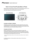
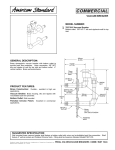
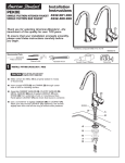
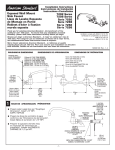
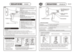
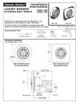
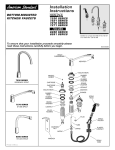
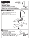
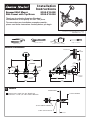
Exposed Wall Mount
Sink Faucet with Top Brace
Installation
Instructions
8344.012.002
8344.012.004
Thank you for selecting American-Standard...
the benchmark of fine quality for over 100 years.
To ensure that your installation proceeds smoothly-please read these instructions carefully before you begin.
Certified to comply with ANSI A112.18.1M
M 9 6 5 0 4 9 R ev. 1. 1
RECOMMENDED TOOLS
Adjustable Wrench
Channel Locks
Phillips Screwdriver
Plumbers' Putty or Caulking
ROUGHING-IN DIMENSIONS
FINISHED WALL
WALL
SUPPORT
12-1/2"
(317mm)
7-3/4" REF.
(198mm)
2-3/8"
(60mm)
BACKFLOW
PREVENTER
1/8"
(3.2mm)
2-1/2"
(63mm)
HOT
COLD
ECCENTRIC
3/4" HOSE
TREADS
6"
(152mm)
8"
(203mm)
1
1/2 N.P.T.
FEMALE
9-3/8"
(237mm)
ROUGH-IN
FINISHED WALL
Prepare water supply lines per "Roughing-in
Dimensions". Install 1/2" NPT. SUPPLY NIPPLES
1-1/4 DIA. OPENING
1/2 NPT. FEMALE THREADS
1/2 NPT. SUPPLY NIPPLE
1/2 to 1
2
FINISH INSTALLATION
Slide COUPLING NUTS (5) onto INLET SHANKS (3).
Thread ESCUTCHEONS (2) fully onto INLET SHANKS (3).
Thread INLET SHANKS (3) onto SUPPLY NIPPLES (1). Distance
between INLET SHANK (3) outlets must be 8" to match the VALVE.
Insert RUBBER WASHERS (4) into INLET SHANK (3).
Attach VALVE (6) to INLET SHANKS (3). Tighten both
COUPLING NUTS (5) firmly.
8"
1
2
5
3
6
4
3
ATTACH SPOUT BRACE
4
3
Attach SPOUT BRACE (1) to SPOUT (2)
and WALL MOUNTING PLATE (3) with the
SPOUT BRACE SCREWS (4) provided.
Mark mounting hole location on wall and
fasten MOUNTING PLATE (3) to wall with
MOUNTING SCREWS (5) provided.
Turn HANDLES TO OFF POSITION.
5
IF WALL MOUNTING PLATE (3) is not
fastened to a wall support within the
wall, use wall anchors with MOUNTING
SCREWS (5).
TEST FAUCET
Slowly turn water supplies on and
check all connections for leaks.
Operate HANDLES to flush water
lines thoroughly.
1
Turn HANDLES to OFF position
and replace AERATOR (1).
Thread ESCUTCHEONS (2)
against finished wall.
4
2
1
OFF
90˚
2
ON
5
SERVICE
To change direction of handle rotation, proceed as follows:
Turn HANDLE to OFF position.
Remove HANDLE SCREW and HANDLE.
Remove SPRING CLIP (1).
Lift STOP WASHER (2), turn 90° and replace.
Replace SPRING CLIP (1).
Replace HANDLE and HANDLE SCREW.
2
90°
1
If spout drips, operate handles several times from OFF to ON position.
Do not force - handles turn only 90°.
CARE INSTRUCTIONS:
DO: SIMPLY RINSE THE PRODUCT CLEAN WITH CLEAR WATER. DRY WITH A SOFT COTTON FLANNEL CLOTH.
DO NOT: DO NOT CLEAN THE PRODUCT WITH SOAPS, ACID, POLISH, ABRASIVES, HARSH CLEANERS, OR A
CLOTH WITH A COARSE SURFACE.
M 9 6 5 0 4 9 R ev 1. 1