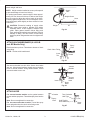
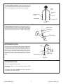
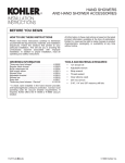
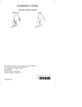
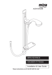
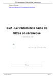
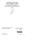
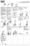
1
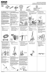
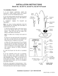
PROVENCE TWO-HANDLE SINK FAUCET PULL-OUT SPRAY W/VACUUM BREAKER ROUGHING-IN DIMENSIONS 3-3/8” 3-3/8” 1-3/4” D. B 8” A C 7/8” Max. 1-15/16” D. D MAX. 7/8” D. E 3/8” O.D. Inlet Tubing 18 2-3/8” OPTIONAL ESCUTCHEON 5/16” O.D. Outlet Tubing Pull-Out Hose 10-1/2” OPTIONAL ESCUTCHEON Roughing-In Notes With escutcheon Without escutcheon A B C D E 3-1/2” 10-1/2” 8-1/4” 1-1/2” 13-1/4” 3” 10” 7-3/4” 2” 13-3/4” BEFORE YOU BEGIN ORDERING INFORMATION: 1-hole installation w/o vacuum breaker White spray and chrome faucet . . . . . . . K-14505-AP-CP Chrome spray and chrome faucet . . . . . . . . . . K-14505-CP Black spray and black faucet. . . . . . . . . . . . . . K-14505-BL White spray and white faucet . . . . . . . . . . . . . . K-14505-O 1-hole installation w/vacuum breaker White spray and chrome faucet . . . . . . . . K-14505-BP-CP Chrome spray and chrome faucet . . . . . . . . K-14505-B-CP Black spray and black faucet . . . . . . . . . . . . . K-14505-B-BL White spray and white faucet. . . . . . . . . . . . . . K-14505-B-O 3-hole installation Escutcheon (optional) . . . . . . . . . . . . . . . . . . . . . . K-14511-** NOTES • • • • • Observe all local plumbing codes. All information in these instructions is based upon the latest product information available at the time of publication. Kohler Co. reserves the right to make changes in product characteristics, packaging, or availability at any time without notice. Please leave these instructions for the consumer. They contain important care, cleaning, and warranty information. Shut off the hot and cold water supplies. Inspect the waste and supply tubing; replace as needed. 113425-2-CA (9501) • • • • Do not straighten the inlet tubes before installing the faucet. The weighted hose requires clearance directly below the faucet body. Plumbing should allow for adequate clearance. A small amount of water may drip from the spray head after the faucet is shut off. This is a normal occurrence caused by the long, flexible hose. The spray-head-to-sink-rim height differs between 1 and 3-hole installations. CAUTION: Risk of fresh water contamination: To avoid potential back-siphonage, do not connect this faucet to a portable dishwasher. Copyright 1995 Kohler Co. TOOLS AND MATERIALS REQUIRED • • • • • • • TOOLS & MATERIALS OPTIONAL • Assortment of screwdrivers Adjustable or open end wrenches Adjustable arc pliers Plumbers putty Supply tubes Tubing cutter Thread sealant Shut-off valves INSTALLATION Slide shank escutcheon over end fittings and hose, and over threaded shank of faucet body. Slide gasket over end fittings and hose, and over threaded shank of faucet body until the gasket seats into recess in shank escutcheon. Feed inlet tubes and hose through sink hole and position faucet onto sink. Faucet handle should face forward when centered between full hot and full cold in the off position. Pull hose up into faucet shank - flush with bottom of shank. Slide washer, bracket and nut over end fittings and hose. Tighten nut to threaded shank. Tighten screws. Body Gasket Groove Gasket Faucet Shank Washer Nut Bracket Screw Fig. #1 For installing optional elongated escutcheon, (3-hole): Place a ring of plumbers putty on underside of escutcheon. Center the spacer with gasket attached, (gasket side down), over the center hole. Position escutcheon over spacer. Body Optional Escutcheon For installation on marble: Do not use plumbers putty. Use self-adhesive gaskets provided. Remove paper backing to expose adhesive. Center gaskets over outside holes, apply adhesive side down. Center the spacer with gasket attached, (gasket side down), over the center hole. Position escutcheon over spacer. Faucet Shank Gasket Gasket Spacer Fig. #2 Unscrew the setscrew with a screwdriver. Slide the spout into the faucet body. Tighten the setscrew. The hot water supply valve is located on the left when you are facing the sink. Threaded Hole Spout Setscrew Fig. #3 113425-2-CA (9501) 2 Kohler Co., Kohler, WI Attach weight and hose. Supply Tube NOTE: Weight must be installed to act as a pull stop and to prevent damage to hose from kinking. For optimal performance, attach weight to hose approximately 26” from loose end of hose. If desired, the weight may be moved to adjust the pullout length of the hose. Carefully tighten weight screw - do not overtighten. Carefully bend supply tubes slightly to allow access for hose connection. Weight Screw Hose Weight CAUTION: Excessive bending of supply tubes may cause hose guide to dislodge from inside threaded shank. If this happens, reinstall hose guide. Place gasket between faucet fitting and hose, and begin threading hose onto fitting. To avoid damage to fitting, use one wrench to hold fitting stationary while using another wrench to tighten the hose. 26” Fig. #4 ATTACH VACUUM BREAKER (K-14502-B and -BP Models Only) Spray Hose Place insert into top of tee. Thread tee to bottom of check valve fitting. Check Valve Fitting NOTE: Tee has a left hand thread. Left Hand Thread Insert Tee Fig. #5 Set vacuum breaker into sink hole. Secure from below with nut. Using thread sealant, thread vacuum breaker hose to vacuum breaker. Using thread sealant, thread vacuum breaker hose to tee. Vacuum Breaker Nut Tee Vacuum Breaker Hose Insert Spray Hose Fig. #6 ATTACH HOSE For vacuum breaker models: set the gasket between the tee and the spray hose. Thread the spray hose into the tee. Gasket Spray Hose Note: Do not overtighten this connection. For non-vacuum breaker models: Thread the spray hose and gasket into the check valve fitting outlet. Turn Clockwise Until Tight Tee Hold Flexible Hose Stationary Spray Hose Fig. #7 Note: Do not overtighten this connection. Kohler Co., Kohler, WI 3 113425-2-CA (9501) To Connect Water Supplies: Copper inlet tubes should be bent carefully to prevent kinking. Attach faucet supply tube to cold supply pipe, then attach the hot supply. Inlet Tube Coupling Nut Compression Fitting Ferrule Coupling Nut Supply Tube Ferrule Fig. #8 If Shut-off Valves Are Used: Cut supply tube to allow required penetration into shut-off valve. Slide coupling nut and ferrule from shut-off valve onto supply. Insert supply tubes into inlets of shut-off valves. Tighten coupling nuts. Supply Tube Coupling Nut Ferrule Shut-Off Valve Fig. #9 AFTER INSTALLATION Hose Remove the spray head and screen gasket. Position the hose in the sink. Turn the hot and cold water supplies on. Turn the faucet handle to the cold side and lift to the ”ON” position. Run water through the faucet for about one minute to remove any debris. Without turning the water off, rotate the faucet to the hot side and flush for one minute. Reinstall the screen gasket and spray head. Check for leaks. Spray Head Screen Gasket Fig. #10 TROUBLESHOOTING Check for leakage at all the joints. Check the handle for smooth operation. Check the finish for damage. To replace the valve cartridge, see the instructions packed with the valve cartridge. 113425-2-CA (9501) 4 Kohler Co., Kohler, WI