1
BEFORE YOU BEGIN
HOW TO USE THESE INSTRUCTIONS
Please read these instructions carefully to familiarize
yourself with the required tools, materials, and installation
sequences. Follow the sections that pertain to your
particular installation. This will help you avoid costly
mistakes. In addition to proper installation, read all
operating and safety instructions.
All information in these instructions is based on the latest
product information available at the time of publication.
Kohler Co. reserves the right to make changes in product
characteristics, packaging, or availability at any time without notice.
NOTES
ORDERING INFORMATION
Observe all local plumbing and building codes.
Inspect waste and supply tubing; replace if
necessary.
If you are installing a new bath, install the drain
before installing the bath. Refer to the
manufacturer’s installation instructions.
Adjustable pop-up drain has removable parts.
Drain “T” is reversible for vertical or horizontal
drainage.
2” brass adjustable pop-up drain
for 24” to 26” baths . . . . . . . . . . . . . . . . . . . . . . . . . K-7167
TOOLS REQUIRED
Assorted screwdrivers
Pliers
Adjustable or open end wrench
Plumbers putty
Pipe wrenches
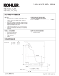
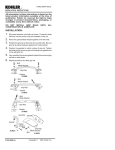
ROUGHING-IN
24” BATH = 21-1/2”
26” BATH = 23-3/4”
7”
3-1/2”
2” N.P.S.
2” O.D.
3”
Fig. #1
18
112035-2-AA (A)
1998 Kohler Co.
INSTALLATION
Apply a ring of plumbers putty or other sealant around
underside of strainer according to the putty
manufacturer’s instructions. Set flat, gasket between
drain ell and the bottom of the bath. Turn strainer into drain
ell.
Plumbers putty
Strainer
Bath
Gasket
Drain Ell
Fig. #2
Tighten drain ell securely by inserting pliers handles into
top of strainer as shown. The handles will catch on bosses
inside of strainer as the strainer is turned into drain ell.
Make sure drain ell tube is facing the front of bath.
Remove excess sealant.
Fig. #3
Attach the gasket to the overflow ell as shown. Make sure
that the tapered end of the gasket is facing up.
Lubricate O-rings on overflow ell and insert into tube.
Align overflow ell with overflow hole in bath.
Gasket
Overflow Ell
Tube
Fig. #4
From inside the bath, assemble hold down plate to
overflow ell with screws provided. Tighten all screws.
Hold Down Plate
Fig. #5
112035-2-AA (A)
2
Kohler Co., Kohler, WI
Tube
Assemble nut and gasket on drain ell, and nut, washer
and cone washer on tube. Align parts with tee as shown.
Insert tubes completely into tee. Align and tighten the
nuts.
Washer
Nuts
Cone
Washer
Attach tailpiece to tee and tighten, Tailpiece may need to
be cut for proper fit. 1” to 2” of tailpiece should fit inside the
trap. Install bath according to manufacturer’s installation
instructions. Make sure the tailpiece on the drain fits
properly into the trap.
Tee
Drain Ell
Gasket
Fig. #6
FOR ABOVE FLOOR INSTALLATIONS: Assemble as
shown, following preceding instructions.
Tube
Washer
Nuts
Cone
Washer
Tee
Drain Ell
Gasket
Fig. #7
If necessary, loosen the screw and adjust linkage to the
proper bath size. The screw should be lined up on the 16
for the 16” bath, 14 for the 14” bath, etc. Refer to the bath
installation instructions to determine your bath size.
Tighten screw after adjusting.
Fig. #8
Insert lift rod assembly into overflow ell. Tighten overflow
hood to overflow ell with the two screws provided.
Fig. #9
Assemble handle to overflow hood with phillips screw
provided. It may be necessary to adjust handle to a
desired position.
Handle
Overflow
Hood
Fig. #10
Kohler Co., Kohler, WI
3
112035-2-AA (A)
Insert drain stopper into drain ell.
Fig. #11
Drain stopper should rise approximately 3/8” above
strainer. Stopper
Nut
Toggle
Fig. #12
If sufficient clearance cannot be obtained by adjusting
stopper, remove lift rod assembly. Loosen screw and slide
adjusting block up on adjusting rail to increase clearance
or down to decrease clearance. Tighten screw and insert
back into overflow ell.
Lift Rod
Assembly
Screw
Adjusting Block
Adjusting Rail
Fig. #13
112035-2-AA (A)
4
Kohler Co., Kohler, WI