1
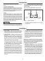
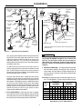
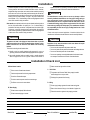
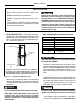
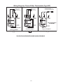
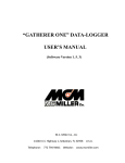
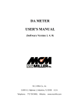
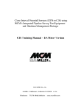
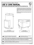
Commercial Point-of-Use Electric Water Heater
USE & CARE MANUAL
®
LISTED
786H
WITH INSTALLATION INSTRUCTIONS FOR THE CONTRACTOR
The purpose of this manual is twofold: one, for
the installing contractor, to provide requirements
and recommendations for the proper installation
and adjustment of the water heater; and two, for
the owner-operator, to explain the features, operation, safety precautions, maintenance and
trouble shooting of the water heater. This manual also includes replacement parts information.
It is imperative that all persons who are expected to install, operate or adjust this water heater
read the instructions carefully so that they may
understand how to do so.
!
Do Not Destroy this Manual. Please read carefully and
keep in a safe place for Future Reference.
!
Recognize this symbol as an Indication of Important
Safety Information!
!
NOTICE: This water heater is designed for use in a commercial application and the installation and maintenance of it
should be performed by qualified, licensed service personnel. If the foregoing assumption is not appropriate, then we
recommend that you obtain and retain our Residential Use & Care Manual.
!
CALIFORNIA PROPOSITION 65 WARNING: This product contains chemicals known to the State of California to cause
cancer, birth defects or other reproductive harm.
Printed in USA
AP12129-4 (01/05)
! General Safety Precautions
Be sure to read and understand the entire Use & Care Manual before attempting to install or operate this water heater. It may save you time and cost.
Pay particular attention to the General Safety Precautions. Failure to follow these warnings could result in serious bodily injury or death. Should you
have problems understanding the instructions in this manual, or have any questions, STOP, and get help from a qualified installer, service technician,
or the local electric utility.
shut off the elements. To find the hot water temperature being
delivered, turn on a hot water faucet and place a thermometer in
the hot water stream and read the thermometer.
To meet commercial water use needs, the thermostat on this water
heater is adjustable to deliver water up to 170°F. However, water
temperatures over 125°F. can cause severe burns instantly or
death from scalds. This is the preferred starting point for setting
the control for supplying general purpose hot water.
The following chart details the relationship of water temperature and time with regard to scald injury and may be
used as a guide in determining the safest water temperature for your applications.
TIME / TEMPERATURE RELATIONSHIPS IN SCALDS
!
Temperature
120° F
125° F
130° F
135° F
140° F
145° F
150° F
155° F
DANGER
Time to Produce Serious Burn
More than 5 minutes
11/2 to 2 minutes
About 30 seconds
About 10 seconds
Less than 5 seconds
Less than 3 seconds
About 11/2 seconds
About 1 second
Table courtesy of Shriners Burn Institute
The temperature of the water in the heater can be regulated
by adjusting the thermostat. To comply with safety regulations the thermostat was set at the factory to a setting corresponding to 120°F.
HOT
R
ESE
T
T
R
ESE
Reset Button
BURN
Thermostat Dial
Pointer
Water temperature over 125°F can
cause severe burns instantly or
death from scalds.
110
170
120
160
150
140 130
TURN OFF
POWER
BEFORE
SERVICING
Children, disabled and elderly are
at highest risk of being scalded.
See instruction manual before
setting temperature at water
heater.
Feel water before bathing or
showering.
Temperature limiting valves are
available, see manual.
Thermostat Protective
Cover
The illustration above shows the temperature adjustment
dial used for setting the water temperature. Refer to Operation section of this manual for detailed instructions in how
to adjust the thermostat(s).
! DANGER
There is a Hot Water SCALD Potential if the thermostat is set too
high.
NOTE: When this water heater is supplying general purpose hot
water requirements for use by individuals, a thermostatically
controlled mixing valve for reducing point of use water
temperature is recommended to reduce the risk of scald injury.
Contact a licensed plumber or the local plumbing authority for
further information.
Safety and energy conservation are factors to be considered when
setting the water temperature on the thermostat. The most energy
efficient operation will result when the temperature setting is the
lowest that satisfies the needs consistent with the application.
Maximum water temperatures occur just after the thermostat has
2
Introduction
The location chosen for the water heater must take into consideration the
following:
lower floors of the structure. Where such areas cannot be avoided, it is
recommended that a suitable catch pan, adequately drained, be installed
under the water heater.
LOCAL INSTALLATION REGULATIONS
This water heater must be installed in accordance with these instructions, local
codes, utility company requirements or, in the absence of local codes, the latest
edition of the National Electrical Code. It is available from some local libraries or
can be purchased from the National Fire Prevention Association, Batterymarch
Park, Quincy, MA 02269 as booklet ANSI/NFPA 70.
NOTE: Auxiliary catch pan installation MUST conform to local codes.
LOCATION
This water heater is designed to meet a wide range of applications. It fulfills a
demand for a small water heater that can be installed in a limited space such as
under counter tops, in cabinets or in a closet. Locate the water heater in a clean
dry area as near as practical to hot water fixtures, or close to the hot water
faucet most frequently used. Place the water heater in such a manner that the
thermostat and element access panels can be removed to permit inspection
and servicing such as removal of elements or checking controls. The water
heater and water lines should be protected from freezing temperatures. Do not
install the water heater in outdoor, unprotected areas.
B
A — Diameter of water
heater plus 2" min.
A
B — Maximum 2"
To open drain, line
should be at least 3/4"
ID and pitched for
proper drainage.
Figure 1. — Auxiliary Catch Pan
! CAUTION
Catch Pan Kits are available from the distributor or store where the water
heater was purchased
The water heater should not be located in an area where leakage of the
tank or connections will result in damage to the area adjacent to it or to
Installation
1. INSPECT SHIPMENT — Inspect the water heater for possible damage.
Check the markings on the rating plate of the water heater to be certain the
power supply corresponds to that for which the water heater is equipped.
The suggested method of controlling thermal expansion is to install
an expansion tank in the cold water line between the water heater and
the check valve. The expansion tank is designed with an air cushion built in that compresses as the system pressure increases,
thereby relieving the over pressure condition and eliminating the repeated operation of the relief valve. Other methods of controlling thermal expansion are also available. Contact your installing contractor,
water supplier, or plumbing inspector for additional information regarding this subject.
2. THERMAL EXPANSION — Determine if a check valve exists in the
inlet water line. It may have been installed in the cold water line as a
separate back flow preventer, or it may be part of a pressure reducing
valve, water meter or water softener. A check valve located in the cold
water inlet line can cause what is referred to as a ”closed water
system”. A cold water inlet line with no check valve or back flow
prevention device is referred to as an ”open” water system.
IMPORTANT!! Do not apply heat to the hot or cold water supply fitting. If
sweat connections are used, sweat tubing to adapter before fitting
adapter to cold water inlet of heater. Any heat applied to the hot or cold
water supply fittings will permanently damage them.
As water is heated, it expands in volume and creates an increase
in the pressure within the water system. This action is referred
to as ”thermal expansion”. In an ”open” water system, expanding
water which exceeds the capacity of the water heater flows back
into the city main where the pressure is easily dissipated.
3. WATER SUPPLY CONNECTIONS — Refer to Fig. 2 or 3 for suggested
typical installation. The installation of unions or flexible copper connectors
on the water connections is recommended so that the water heater may be
easily disconnected for servicing if necessary. Connect cold water supply
line to 3/4” pipe connection near the bottom of water heater. (Refer to
Figure 2.) Install a shut-off valve and a drain valve (not supplied) in the cold
water line near the water heater (Refer to Fig. 2.). Connect hot water line to
3/4” pipe connection marked HOT on the side near the top of the water
heater. On the some models, the hot and cold water connections are 1/2”
pipe connections and are located on top of the heater. (Refer to Figure 3.)
A drain valve is supplied on these models. Local codes may require an
Anti-Syphon device on the water inlet of a side connect water heater.
A ”closed water system”, however, prevents the expanding
water from flowing back into the main supply line, and the result
of ”thermal expansion” can create a rapid, and dangerous pressure increase in the water heater and system piping. This rapid
pressure increase can quickly reach the safety setting of the relief valve, causing it to operate during each heating cycle. Thermal expansion, and the resulting rapid, and repeated expansion
and contraction of components in the water heater and piping
system can cause premature failure of the relief valve, and possibly the heater itself.Replacing the relief valve will not correct
the problem!
3
Installation
Vacuum Relief Valve
(Not Supplied)
Union
Recommended
Heat Trap
6" Min.
Unions
Anode
Hot Water
Outlet to Fixtures
Temperature
Pressure
Relief Valve
If required, install per local codes
and valve manufacturer’s
instructions.
Temperature & Pressure
Relief Valve
Shut-Off Valve
Cold Water Supply
To Cold Water
Supply
Relief Valve
Discharge
Line to suitable
open drain
Power Supply Cord
21/2 gal. models only
Relief Valve
Discharge Line
Drain valve*
Shut-Off
Valve
Hot Water Outlet
(To Fixtures)
Jacket Access Panel
6"
Air Gap
6"
Auxiliary
Catch Pan
Auxiliary Catch Pan
Opening for
1/2" or 3/4"
Electrical Fitting
(Use only Copper
Conductors)
Drain Valve
(Not Supplied)
Auxiliary Catch Pan Drain Line
Suitable Open Drain
*Drain valve is located below and to right of Jacket Access Panel and is not
visible in this view.
Jacket Access
Panel
Figure 3. — Typical Under Counter Top Connect Installation
Figure 2. — Typical Side Connect Installation
4. RELIEF VALVE — A new combination pressure and temperature relief
valve, complying with the Standard for Relief Valves and Automatic Gas
Shutoff Devices for Hot Water Supply Systems, ANSI Z21.22, must be
installed in the opening provided and marked for the purpose on the
water heater. (Refer to Fig. 2 or 3.) No valve of any type should be
installed between the relief valve and the tank. Local codes shall govern
the installation of relief valves.
! WARNING
Tank MUST BE full of water before power is turned on. Heating
element(s) WlLL BE DAMAGED if energized for even a short time while
tank is dry. The water heater’s warranty does not cover damage or
failure resulting from operation with an empty or partially empty tank.
(Reference is made to the limited warranty for complete terms and
conditions.)
The pressure rating of the relief valve must not exceed 150 psi, the
maximum working pressure of the water heater as marked on the rating
plate. The BTUH Rating of the relief valve must not be less than the
input rating of the water heater as indicated on the rating label located on
the front of the heater (1 watt = 3.412 BTUH).
6. ELECTRICAL CONNECTIONS — The voltage requirements and wattage
load for all heaters is specified on the rating plate. Table 1 recommends
minimum branch circuit sizing based on the National Electrical Code. All
wiring must conform to local codes or latest edition of National Electrical
Code ANSI/NFPA 70.
Connect the outlet of the relief valve to a suitable open drain so that the
discharge water cannot contact live electrical parts and to eliminate
potential water damage. Piping used should be of a type approved for hot
water distribution. The discharge line must be no smaller than the outlet of
the valve and must pitch downward from the valve to allow complete
drainage (by gravity) of the relief valve and discharge line. The end of the
discharge line should not be threaded or concealed and should be
protected from freezing. No valve of any type, restriction or reducer
coupling should be installed in the discharge line.
Some models are supplied with a plug connected power supply cord for use
only in 120 VAC applications. The cord must be connected to a properly
Total
Water Heater
Wattage
1440
1500
2000
2500
3000
4500
6000
5. TO FILL WATER HEATER — Make certain drain valve is completely
closed. Open shut-off valve in cold water supply line. Open each hot water
faucet slowly to allow air to vent from the water heater and piping. A steady
flow of water from the hot water faucet(s) indicates a full water heater.
Table 1. —
4
Recommended Over
Current Protection
(Fuse or Circuit Breaker)
Amperage Rating
Copper Wire Size AWG Based on N.E.C.
Table 310-16 (75°C.)
120V 208V 240V 277V 480V 120V 208V 240V 277V 480V
15
--------14
--------20
15
15
15
15
12
14
14
14
14
25
15
15
15
15
10
14
14
14
14
30
15
15
15
15
10
14
14
14
14
35
20
20
15
15
8
12
12
14
14
--30
25
25
15
--10
10
10
14
--40
35
30
20
--8
8
10
12
Branch Circuit Sizing and Wire Size
Guide Based on N.E.C. ANSI / NFPA 70
Installation
grounded receptacle on a branch circuit with copper conductors, an over
current protection device and a suitable disconnect means. If desired,
straight field wiring connections can be made to these models by removing
the access cover on front of the heater and disconnecting the cord set from
the thermostat and the grounding lug. Remove the cord set and strain relief
bushing from the junction bracket. The hole in the junction bracket will
accommodate 1/2” or 3/4” electrical fittings. Refer to wiring diagrams on back
cover of this manual for wiring connections.
separate conductor for grounding. It should be attached to the ground
terminals of the water heater and the electrical distribution box.
! WARNING
The manufacturer’s warranty does not cover any damage or defect
caused by installation, attachment or use of any type of energy saving or
other unapproved devices (other than those authorized by the
manufacturer) into, onto or in conjunction with the water heater. The use
of unauthorized energy saving devices may shorten the life of the water
heater and may endanger life and property. The manufacturer disclaims
any responsibility for such loss or injury resulting from the use of such
unauthorized devices.
Some models are completely wired to the junction bracket inside the jacket at
the front of the water heater. An opening for 1/2” or 3/4” electrical fitting is
provided for field wiring connections. A separate branch circuit with copper
conductors, overcurrent protective device and suitable disconnecting
means must be provided by a qualified electrician. Refer to wiring diagrams
on back cover of this manual for wiring connections.
If local codes require external application of insulation blanket kits the
manufacturer’s instructions included with the kit must be carefully followed.
! CAUTION
! CAUTION
The presence of water in the piping and water heater does not provide
sufficient conduction for a ground. Non-metallic piping, dielectric unions,
flexible connectors etc. can cause the water heater to be electrically
isolated.
The branch circuit wiring should include either:
Application of any external insulation to this water heater will require
careful attention to the following:
• Do not cover the temperature and pressure relief valve.
• Do not cover jacket access panels to thermostats and heating elements.
A. Metallic conduit or metallic sheathed cable approved for use as a
grounding conductor and installed with fittings approved for the purpose.
B. Non-metallic sheathed cable or metallic conduit or metallic sheathed
cable not approved for use as a ground conductor shall include a
• Do not cover electrical junction box of water heater.
• Do not cover operating or warning labels attached to the water heater
nor attempt to relocate them on exterior of insulation blanket.
Installation Check List
❑ Water connections tight and free of leaks
A. Water Heater Location
C. Relief Valve
❑ Close to area of heated water demand.
❑ Temperature and Pressure Relief Valve properly installed
❑ Indoors and protected from freezing temperatures.
and discharge line run to open drain
❑ Area free of flammable vapors.
❑ Discharge line protected from freezing.
❑ Provisions made to protect area from water damage.
D. Wiring
❑ Sufficient room to service water heater.
❑ Power supply voltage agrees with water heater rating plate.
B. Water Supply
❑ Branch circuit wire and fusing or circuit breaker of proper size.
❑ Water heater completely filled with water.
❑ Electrical connections tight and unit properly grounded.
❑ Water heater and piping air vented.
Model No.
Serial No.
Date of Installation
5
Installed By:
Operation
SAFETY PRECAUTIONS
A. Do turn off power to water heater if it has been subjected to over
heating, fire, flood or physical damage.
! CAUTION
Hydrogen gas can be produced in a hot water system served by this
water heater that has not been used for a long period of time
(generally two weeks or more). HYDROGEN GAS IS EXTREMELY
FLAMMABLE!! To dissipate such gas and to reduce risk of injury, it is
recommended that the hot water faucet be opened for several
minutes at the kitchen sink before using any electrical appliance
connected to the hot water system. If hydrogen is present, there will
probably be an unusual sound such as air escaping through the pipe
as the water begins to flow. Do not smoke or use an open flame near
the faucet at the time it is open.
B. Do Not turn on water heater unless it is filled with water.
C. Do Not turn on water heater if cold water supply shut-off valve is
closed.
D. If there is any difficulty in understanding or following the OPERATION
or MAINTENANCE instructions, it is recommended that a qualified
person or serviceman perform the work.
1. WATER TEMPERATURE SETTING — The temperature of the water in
the water heater can be regulated by setting the temperature dial of the
adjustable surface mounted thermostat located behind the jacket access
panel. To comply with safety regulations the thermostat is factory set at
120° F or less where local codes require.
Temperature
120° F
125° F
130° F
135° F
140° F
145° F
150° F
155° F
R
ESE
ESE
T
T
Reset Button
TIME / TEMPERATURE RELATIONSHIPS IN SCALDS
R
Thermostat Dial
Pointer
Time to Produce Serious Burn
More than 5 minutes
11/2 to 2 minutes
About 30 seconds
About 10 seconds
Less than 5 seconds
Less than 3 seconds
About 11/2 seconds
About 1 second
Table courtesy of Shriners Burn Institute
110
170
120
160
150
140
! DANGER
130
TURN OFF
POWER
BEFORE
SERVICING
Make certain power to water heater is OFF before removing jacket
access panel FOR ANY REASON.
If adjustment is necessary, turn off power to water heater, remove
jacket access panel and insulation exposing thermostat. The thermostat
protective cover should not be removed. Set thermostat dial pointer,
with a small screwdriver, to desired temperature. (Refer to Fig. 4.)
Replace insulation and jacket access panel. Turn on power to water
heater.
Thermostat Protective
Cover
CAUTION!! — Hotter water increases the risk of SCALDING!
This illustration shows the temperature adjustment dial used for setting the
water temperature. Refer to Section 1 - Water Temperature Setting, above, for
more details and safety instructions regarding water temperature setting.
2. SAFETY CONTROLS — The water heater is equipped with a
combination Thermostat and Temperature Limiting Control (ECO) that is
located above the heating element in contact with the tank surface. If for
any reason the water temperature becomes excessively high, the
Temperature Limiting Control (ECO) breaks the power circuit to the
heating element. Once the control opens, it must be reset manually.
Figure 4. — Thermostat and Protective Cover.
Safety and energy conservation are factors to be considered when
selecting the water temperature setting of the water heater’s thermostat.
The lower the temperature setting the greater the savings in energy and
operating costs.
! DANGER
! CAUTION
The cause of the High Temperature Condition must be investigated by
qualified service personnel and corrective action taken before placing
the water heater in service again.
There is a Hot Water SCALD Potential if the thermostat is set too high.
NOTE: When this water heater is supplying general purpose hot
water requirements for use by individuals, a thermostatically
controlled mixing valve for reducing point of use water
temperature is recommended to reduce the risk of scald injury.
Contact a licensed plumber or the local plumbing authority for
further information.
To reset Temperature Limiting Control, turn off power to water heater,
remove jacket access panel and insulation. The thermostat protective
6
Operation
cover SHOULD NOT be removed. (Refer to Fig. 4.) Press red
“RESET” button. Replace insulation and jacket access panel before
turning on power to water heater.
In order to drain water heater, turn off cold water supply, then it is
necessary to open a hot water faucet or lift the handle on the relief valve
to admit air to the tank. Attach a garden hose to the drain valve on the
water heater and direct the stream of water to a drain where it will do no
damage.
3. EMERGENCY INSTRUCTIONS —
! WARNING
! DANGER
If water heater has been subjected to flood,fire,or physical damage,
turn off power and water to water heater. Do not operate the water
heater again until it has been thoroughly checked by qualified service
personnel.
The water drained from the tank may be hot enough to present a
SCALD HAZARD and should be directed to a suitable drain to prevent
injury or damage.
4. LONG TIME SHUT-DOWN — If the water heater is to remain idle for an
extended period of time, the power and water to the water heater should
be turned off to conserve energy. The water heater and piping should be
drained if they might be subjected to freezing temperatures.
6. ANODE — This water heater is equipped with an anode rod designed to
prolong the life of the glass lined tank. The anode is slowly consumed
cathodically, thereby eliminating or minimizing corrosion of the glass lined
tank.
NOTE: Refer to “Hydrogen Gas Caution” in Safety Precautions
Section on page 6.
Water sometimes contains a high sulfate and/or mineral content and
together with the cathodic protection process can produce a hydrogen
sulfide or rotten egg odor in the heated water. Chlorination of the water
supply should minimize the problem.
After a very long shut-down period, the water heater’s operation and
controls should be checked by qualified service personnel. Make certain
the water heater is completely filled before again placing it in operation .
NOTE: Do not remove the anode rod from the water heater’s tank,
except for inspection and/or replacement, as operation with the
anode rod removed will shorten the life of the glass lined tank and
will exclude warranty coverage.
5. DRAINING HEATER —
! CAUTION
Shut off power to water heater before draining water.
Maintenance
Properly maintained, your water heater will provide years of dependable
trouble-free service. It is suggested that a routine preventive maintenance
program be established and followed by the user. It is further recommended
that a periodic inspection of the operating controls, heating element and wiring
should be made by service personnel qualified in electric appliance repair.
NOTE: If the temperature and pressure relief valve on the water heater
discharges periodically, this may be due to thermal expansion in a
“Closed” water system. Contact the water supplier or your plumbing
contractor on how to correct this. DO NOT plug the relief valve outlet.
D. A water heater’s tank can act as a settling basin for solids suspended in the
water. It is, therefore, not uncommon for hard water deposits to accumulate
in the bottom of the tank. It is suggested that a few quarts of water be
drained from the water heater’s tank through the drain valve every month
to clean the tank of these deposits.
1. ROUTINE PREVENTATIVE MAINTENANCE
A. Most electrical appliances make some sound when in operation, even
when new. If the hissing or singing sound level increases excessively, the
electric heating element may require cleaning. Contact your installer or
plumbing contractor to inspect.
E. Rapid closing of faucets or solenoid valves in automatic water using
appliances can cause a pounding “water hammer” sound. “Water hammer”
can be described as a banging noise heard in a water pipe following an
abrupt alteration of the flow with resulting pressure surges. Strategically
located risers in the water pipe system can be used to minimize the
problem. Also water hammer arresting devices are usually available from
your plumber or local plumbing supply store.
B. The area near the water heater must be kept free of flammable liquids such
as gasoline or paint thinners, adhesives or other combustible materials.
C. At least once a year, lift and release the lever handle on the temperature
pressure relief valve, located near the top of the water heater, to make
certain the valve operates freely and allow several gallons to flush through
discharge line. Make certain the discharged water is directed to an open
drain.
2. ANODE ROD INSPECTION — The anode rod should be removed from
the water heater’s tank annually for inspection and replaced when more
than 6” of core wire is exposed at either end of the rod. Refer to Fig. 2 for
anode rod location. Make certain cold water supply is turned off before
removing anode rod.
! DANGER
Before manually operating the relief valve, make certain no one will be
exposed to the danger of coming in contact with the hot water released by
this valve. The water may be hot enough to create a SCALD hazard. The
water released should be directed to a suitable drain to prevent injury or
damage.
7
Replacement Parts List
Instructions for placing a Parts Orders:
Address parts orders to the distributor or store from where the heater was purchased.
All parts orders should include:
1. Model number and Serial number of heater (from rating plate).
2. Specify voltage and wattage as marked on rating plate.
3. Part Description (as noted below) and number of parts desired.
Top Connect Models
120 or 240 Volt Operation
6
4
7
5
T ES E
ER
R
SE T
09
001
CS
ID-
041
031
011
O - M 021
RE
HT
10
FFO
RE NRU
E WO T
GNROFEP
ICI B
VR
ES
9
3
1
2
8
Ref.
No.
Part Description
Qty.
Req’d
1.
2.
3.
4.
5.
6.
7.
8.
9.
10.
Heating Element
Heating Element Gasket
Thermostat Bracket
Thermostat
Thermostat Protective Cover
Cavity Insulation
Jacket Access Panel
Drain Valve
Drain Valve Shroud
Electrical Cord Set (120 VAC models ONLY)
1
1
1
1
1
1
1
1
1
1
! CAUTION
For your safety, DO NOT attempt repair of electrical wiring, thermostats, heating elements or other operating controls. Refer repairs to qualified service
personnel.
8
Replacement Parts List
Instructions for placing a Parts Orders:
Address parts orders to the distributor or store from where the heater was purchased.
All parts orders should include:
1. Model number and Serial number of heater (from rating plate).
2. Specify voltage and wattage as marked on rating plate.
3. Part Description (as noted below) and number of parts desired.
Side Connect Models
120, 208, 240, 277 or 480
Volt Operation
11
12
10
8
R
4
E
5
6
7
SE T
RE
SE T
90
140
130
100
110 - D I S C
120
O
MER
TH
N OFF
TUR ER
POW
ORE
NG
BEF
VICI
SER
10
2
9
1
3
Ref.
No.
1.
2.
3.
4.
5.
6.
7.
8.
9.
10.
11.
12.
Part Description
Heating Element
Heating Element Gasket
Thermostat Bracket
Thermostat
Thermostat Protective Cover
Cavity Insulation
Jacket Access Panel
Nipple, Hot Outlet/J-Tube (Not Shown)
Nipple, Cold Inlet
Shroud
Anode Rod
Snap Bushing
Qty.
Req’d
1
1
1
1
1
1
1
1
1
As Req’d
1
1
! CAUTION
For your safety, DO NOT attempt repair of electrical wiring, thermostats, heating elements or other operating controls. Refer repairs to qualified service
personnel.
9
Trouble Shooting Guide
NATURE OF TROUBLE
No Hot Water
POSSIBLE CAUSE
SERVICE
1. Manual switch turned off
2. Improper Wiring
3. No Power — blown fuse or circuit breaker tripped
a. Shorted wiring
b. Circuit overloaded
c. Improper wiring
d. Grounded element or thermostat
4. Manual Reset Limit (ECO) open
a. Thermostat(s) defective
b. Thermostat out of calibration
c. Heat build-up due to loose wires
d. Defective Limit (ECO)
Turn to ON
** Rewire per Wiring Diagram
**
**
**
**
**
**
**
**
Replace or repair
Provide adequate circuit or reduce load
Rewire per diagram
Replace
Refer to "Operation Section"
Replace
Lower setting or replace
Tighten wire connections
Replace
Not enough Hot Water
1. Heater undersized
2. Defective Element(s)
3. Miswired or defective thermostat
causing only one element to work
Reduce rate of hot water use
** Check amperage, replace element if low
** Check wiring or replace
Water too hot or not
hot enough
1. Thermostat setting too high or low
2. Thermostat out of calibration
Change setting as required
** Replace
Noisy heating element(s)
1. Scale build-up on elements
** Remove and clean
! CAUTION
** For your safety, DO NOT attempt repair of Electrical Wiring, Thermostat(s), Heating Elements or other Operating Controls. Refer repairs to qualified
service personnel.
How to Obtain Service Assistance
1. Should you have any questions about your new water heater, or if it
requires adjustment, repair, or routine maintenance, it is suggested that
you first contact your installer, plumbing contractor or previously agreed
upon service agency. In the event that the firm has moved, or is
unavailable, refer to the telephone directory commercial listings or local
utility for qualified service assistance.
2. Should your problem not be solved to your complete satisfaction, you
should then contact the Manufacturer’s National Service Department at
the following address:
2600 Gunter Park Drive
Montgomery, Alabama 36109-1413
Phone: 1-800-432-8373.
10
When contacting the manufacturer, the following information should be
made available:
a. Model and serial numbers of the water heater as shown on the rating
plate attached to the jacket of the heater.
b. Address where water heater is located and can be seen.
c. Name and address of installer and any service agency who performed
service on the water heater.
d. Date of original installation and dates any service work was performed.
e. Details of the problem as you can best describe them.
f. List of people, with dates, who have been contacted regarding your
problem.
THIS PAGE WAS INTENTIONALLY LEFT BLANK.
11
Wiring Diagrams Therm-O-Disc Thermostats (Type 59T)
WHITE
2
4
BLACK
HEATING
ELEMENT
JUNCTION
BOX
THERMOSTAT
& HIGH TEMP.
LIMIT (ECO)
2
1
2
BLACK
1
1
2
120 V Plug Connected
Cord Set ONLY
2
HEATING
ELEMENT
N
BLACK
THERMOSTAT
& HIGH TEMP.
LIMIT (ECO)
BLACK
1
3
RED
2
1
G*
WHITE
THERMOSTAT
& HIGH TEMP.
LIMIT (ECO)
H
L
BLACK
BLACK
1
G
JUNCTION
BOX
L
RED
N
DISTRIBUTION PANEL
JUNCTION
BOX
G*
H
TO PROPERLY GROUNDED
RECEPTACLE ON BRANCH CIRCUIT
TO ELECTRICAL DISTRIBUTION PANEL
BRANCH CIRCUIT
TO ELECTRICAL
BRANCH CIRCUIT
TO ELECTRICAL
DISTRIBUTION PANEL
HEATING
ELEMENT
120 V ONLY
SINGLE ELEMENT
FIG. A
SINGLE ELEMENT
FIG. B
SINGLE ELEMENT
FIG. C
THIS ELECTRIC WATER HEATER IS WIRED AS INDICATED ABOVE
12