1
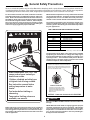
Commercial Electric Water Heater
USE & CARE MANUAL
®
WITH INSTALLATION INSTRUCTIONS FOR THE CONTRACTOR
LISTED
18GO
The purpose of this manual is twofold: one, for the installing contractor, to
provide requirements and recommendations for the proper installation and
adjustment of the water heater; and two, for the owner-operator, to explain
the features, operation, safety precautions, maintenance and trouble shooting of the water heater. This manual also includes replacement parts information.
It is imperative that all persons who are expected to install, operate or adjust this water heater read the instructions carefully so that they may understand how to do so.
Tank Type Models
Surface Mounted or Immersion Thermostats
!
Do Not Destroy this Manual. Please read carefully and keep in a safe place for Future Reference.
Booster Models
Immersion Thermostats Only
!
Recognize this symbol as an Indication of
Important Safety Information!
!
NOTICE: This water heater is designed for use in a commercial application and the installation and maintenance of it should be performed by qualified, licensed service personnel. If the foregoing assumption is not
appropriate, then we recommend that you obtain and retain our Residential Use & Care Manual.
!
CALIFORNIA PROPOSITION 65 WARNING: This product contains chemicals known to the State of California
to cause cancer, birth defects or other reproductive harm.
Printed in USA
AP11146-8 (01/05)
! General Safety Precautions
Be sure to read and understand the entire Use & Care Manual before attempting to install or operate this water heater. Pay particular attention to the
following General Safety Precautions. Failure to follow these warnings could result in serious bodily injury or death . Should you have any problems
understanding the instructions in this manual, STOP, and get help from a qualified installer or service technician or the local utility.
To meet commercial water use needs, all Immersion thermostat model water heaters are adjustable to deliver water up to
190°F. Surface mounted thermostat model water heaters are
adjustable to deliver 160°F for the 50 gallon models and 180°F
for the 85 and 120 gallon models. However, water temperatures over 125°F can cause severe burns instantly or death
from scalds. This is the preferred starting point for setting the
control for supplying general purpose hot water.
Maximum water temperatures occur just after the thermostat
has shut off the elements. To find the hot water temperature
being delivered, turn on a hot water faucet and place a thermometer in the hot water stream and read the thermometer.
The following chart details the relationship of water temperature and time with regard to scald injury and may be
used as a guide in determining the safest water temperature
for your applications.
TIME / TEMPERATURE RELATIONSHIPS IN SCALDS
!
Temperature
120° F.
125° F.
130° F.
135° F.
140° F.
145° F.
150° F.
155° F.
DANGER
Time to Produce Serious Burn
More than 5 minutes
1 1 / 2 to 2 minutes
About 30 seconds
About 10 seconds
Less than 5 seconds
Less than 3 seconds
About 1 1 / 2 seconds
About 1 second
Table courtesy of Shriners Burn Institute
HOT
The temperature of the water in the heater can be regulated
by adjusting the thermostat. To comply with safety regulations the thermostat was set at the factory to a setting corresponding to 120°F. The illustration below pictures the thermostats used on the water heaters covered in this manual
and how to adjust the water temperature.
WA
R
VERY
Children, disabled and elderly are
at highest risk of being scalded.
See instruction manual before
setting temperature at water
heater.
Feel water before bathing or
showering.
Temperature limiting valves are
available, see manual.
ESE
R
ESE
T
HO
LOW
HI
M
Water temperature over 125°F can
cause severe burns instantly or
death from scalds.
T
R
To adjust the water temperature on Surface Mounted Thermostat models, insert a small straight screwdriver into slotted screw
of indicator and move indicator to desired setting.See Operation Section of this Manual for details.
T
BURN
MED
TURN OFF
POWER
BEFORE
SERVICING
Immersion Thermostat
To adjust the water temperature on Immersion Thermostat models,turn thermostat dial
to align desired mark with index line above
thermostat. See Operation Section of this
Manual for details.
Surface Mounted
Thermostat
CAUTION!! — Hotter water increases the risk of SCALDING!
! DANGER
There is a Hot Water SCALD Potential if the thermostat is set
too high.
NOTE: When this water heater is supplying general purpose
hot water requirements for use by individuals, a thermostatically controlled mixing valve for reducing point of use water
temperature is recommended to reduce the risk of scald injury. Contact a licensed plumber or the local plumbing authority for further information.
Safety and energy conservation are factors to be considered
when setting the water temperature on the thermostat. The
most energy efficient operation will result when the temperature setting is the lowest that satisfies the needs consistent
with the application.
2
Introduction
C. FOR THE TANK TYPE MODELS, the minimum distance to provide
adequate clearance for protection of combustible material is 0 inches from jacket and 18 inches from access door. However, additional clearance for accessibility to permit inspection and servicing such
as removing heating elements or checking controls must be provided. All models are approved for installation on combustible flooring.
! WARNING
Read and Review this entire Manual with special emphasis on the Installation Section (Pages 3 - 6) and Operation Section (Pages 7 - 8) prior to any installation
work.
FOR THE BOOSTER MODELS
A minimum clearance of 18 inches on the right side of the Booster
model is required for removal of the heating element(s) when required
for service or inspection.
LOCAL INSTALLATION REGULATIONS—This water heater must be
installed in accordance with these instructions, local codes, utility company requirements, and/or in the absence of local codes, the latest edition of the American National Standard / National Electrical Code. A copy
of which can be purchased from the National Fire Protection Association, 1 Batterymarch Park, Quincy, MA 02269 as booklet NFPA 70.
Four separate 5/16-18 threaded openings are provided on the top,
rear and bottom panels, so the heater may be bolted to a horizontal
or vertical surface. If installed on a counter top, or stacked vertically in multiples, insert bolts and/or washers in bottom threaded openings to provide a minimum 1/4” clearance so door hinges will not bind.
LOCATION
A. The water heater should be installed in a clean, dry location as close
as practical to the area of greatest hot water demand. Long hot water
lines should be insulated to conserve water and energy. The water
heater and water lines should be protected from exposure to freezing temperatures. DO NOT install the water heater in an outdoor, unprotected area.
Factory designed accessories available for the Booster square model
are: six inch adjustable stainless steel legs and a bracket kit for slide
in “under counter” mounting or wall mounting of the water heater.
´
D. RESTAURANT INSTALLATION:
If the water heater is to be installed in a restaurant, or other location
where NSF International listing is required, it must be weather sealed
to the floor, a raised base, or shelf so that seepage cannot accumulate under it; or elevated to provide at least (6) inches of clearance from the floor.
B. The water heater should not be located in an area where leakage of
the tank or connections will result in damage to the area adjacent to
it or to lower floors of the structure. When such areas cannot be avoided, it is recommended that a suitable catch pan, adequately drained,
be installed under the water heater.
The standard legs supplied with the Booster models provide the six
(6) inches of clearance in accordance with NSF International requirements.
For the Tank Type models, a factory designed sealing kit is available from the distributor or store where the water heater was purchased. When installed according to the instructions supplied with
the kit, these heaters will meet the NSF International requirements.
NOTE: Auxiliary catch pan installation MUST conform the applicable local codes.
Installation
vide hot water for sanitizing rinse. Note: Adjust the pressure reducing valve to the dishwasher manufacturer’s recommended pressure (usually between 15 and 25 psi), with water flowing to the dishwasher.
! WARNING
The manufacturer’s warranty does not cover any damage
or defect caused by installation, or attachment or use
of any special attachment such as energy saving devices (other than those authorized by the manufacturer) into, onto, or in conjunction with the water heater.
The use of such unauthorized devices may shorten the
life of the water heater and may endanger life and property. The manufacturer disclaims any responsibility for
such loss or injury resulting from the use of such unauthorized devices.
2. THERMAL EXPANSION — Determine if a check valve exists
in the inlet water line. It may have been installed in the cold
water line as a separate back flow preventer, or it may be part
of a pressure reducing valve, water meter or water softener. A
check valve located in the cold water inlet line can cause what
is referred to as a ”closed water system”. A cold water inlet
line with no check valve or back flow prevention device is referred to as an ”open” water system.
1. INSPECT SHIPMENT—for possible damage. The manufacturer’s
responsibility ceases upon delivery of goods to the carrier in good
condition. Any claims for damage, shortage in shipments, or nondelivery must be filed immediately against carrier by consignee.
Refer to Fig. 1 for installation with commercial dishwasher to pro-
As water is heated, it expands in volume and creates an increase
in the pressure within the water system. This action is referred to
as ”thermal expansion”. In an ”open” water system, expand3
Installation
Water Shock
Arrestor
Temperature /
Pressure Gauge
Pressure Reducing
Valve with By-pass
SYSTEM SENTINEL
Indicators
Thermostat(s)
Dial(s)
High Temp
Limit Control
Shut-off
Valve
Dishwasher
Vacuum Relief Valve
(Not Supplied)
Water Inlet
Legs
If required, install per local codes
and valve manufacturer’s
instructions.
Check Valve
Circulation Return Line
6” Air Gap
Relief Valve
Discharge Line
Open Drain
Figure 1. — Recommended installation for dishwashing sanitizing rinse application
ing water which exceeds the capacity of the water heater flows
back into the city main where the pressure is easily dissipated.
The suggested method of controlling thermal expansion is to
install an expansion tank in the cold water line between the water
heater and the check valve. The expansion tank is designed with
an air cushion built in that compresses as the system pressure
increases, thereby relieving the over pressure condition and eliminating the repeated operation of the relief valve. Other methods of
controlling thermal expansion are also available. Contact your
installing contractor, water supplier, or plumbing inspector for
additional information regarding this subject.
A ”closed water system”, however, prevents the expanding
water from flowing back into the main supply line, and the result of
”thermal expansion” can create a rapid, and dangerous pressure increase in the water heater and system piping. This rapid
pressure increase can quickly reach the safety setting of the relief
valve, causing it to operate during each heating cycle. Thermal
expansion, and the resulting rapid, and repeated expansion and
contraction of components in the water heater and piping system
can cause premature failure of the relief valve, and possibly the
heater itself.Replacing the relief valve will not correct the
problem!
If a recirculation line is installed, the return connection should be made
to a tee close to the inlet connection on the water heater. A check
valve should always be installed in the recirculation line to prevent
cold water from entering.
Storage Tank Temperature & Pressure Relief Valve
Refer to Local Codes
Hot Outlet
Storage Tank
Temperature & Pressure Relief Valve
(Not visible in this view)
Refer to Local Codes
Temperature & Pressure Relief Valve
Discharge Pipe to suitable open drain
Return Outlet
Vacuum Relief Valve
(Not Supplied)
2”
Optional Return Outlet
Thermal Expansion
Tank
(If Required)
If required, install per local codes
and valve manufacturer’s
instructions.
Recirculation Loop
Branch Circuit from
Electrical Distribution Panel
Cold Water Inlet
Check Valve
Shut-off Valve
NOTES:
1.) Heater’s Outlet Piping must have
upward slope, otherwise use Circulator.
Air Gap 6”
Temperature & Pressure Relief Valve(s)
Discharge Pipe(s) to suitable open drain
Figure 2. — Typical Gravity Circulating System
4
2.) If vertical tank is used, follow same layout.
Installation
Storage Tank Temperature & Pressure Relief Valve
Refer to Local Codes
Hot Outlet
Cold Water Inlet
Recirculation Loop
Temperature & Pressure Relief Valve
(Not visible in this view)
Refer to Local Codes
Storage Tanks
Shut-off Valve
Recirculator
Manifolds
Circulator
Control
(Optional*)
Branch Circuit from
Electrical Distribution Panel
Check Valve
Vacuum Relief Valve
(Not Supplied)
Air Gap
6”
Circulator*
* Circulator may be wired to run continuously
without the control
Temperature & Pressure Relief Valve(s)
Discharge Pipe(s) to suitable open drain
If required, install per local codes
and valve manufacturer’s
instructions.
Figure 3. — Typical Forced Circulation Tank System with factory supplied jacketed and insulated storage tanks.
Factory designed Equa-Flow Manifolds, and jacketed, insulated
storage tanks are available.
Z21.22, is factory installed on this water heater at the time of manufacture. No valve is to be placed between the relief valve and the
water heater. For a circulating tank installation, the separate storage tank(s) must have similar protection. Local codes shall govern the installation of relief valves.
3. WATER CONNECTIONS—This heater may be connected individually in multiples with others, or with an external hot water storage
tank. It may also be used to boost the temperature of preheated
water.
The pressure rating of the relief valve must not exceed 150 psi
(160 psi for ASME models), the maximum working pressure of the
water heater as marked on the rating plate. The Btu/h rating of the
relief valve must not be less than the input rating of the water heater
as indicated on the rating plate located on the front of the heater.
(1 watt = 3.412 Btu/h).
Inlet and outlet water connections are clearly marked next to the
connections on the heater. Use only clean, new galvanized steel,
copper or approved plastic for pipe for water connections. Local
codes shall govern the exact type of material to be used. The installation of unions on the inlet and outlet water lines and a shutoff valve in at least the cold water line is recommended so the water
heater may be easily disconnected for servicing. Dielectric unions
are not required for protection of the water heater.
Connect the outlet of the relief valve to a suitable open drain so
that the discharge water cannot contact live electrical parts. The discharge line must pitch downward from the valve to allow complete
draining (by gravity) of the relief valve and discharge line and be no
smaller than the outlet of the valve. The end of the discharge line
should not be threaded or concealed and should be protected from
freezing. No valve of any type, restriction or reducer coupling should
be installed in the discharge line. Local codes shall govern the installation of relief valves.
When this water heater is supplying general purpose hot water requirements for use by individuals, a thermostatically controlled
mixing valve is recommended to reduce the risk of scald injury.
Contact a licensed plumber or the local plumbing authority for further information.
Thermometer(s) should be installed so that they indicate the temperature of the water at or near the outlet of the water heater and
storage tank(s) if provided. See Fig. 2 or 3.
5. TO FILL WATER HEATER — Make certain drain valve is completely closed. Open shut-off valve in cold water supply line. Open
each hot water faucet slowly to allow air to vent from the water
heater and piping. A steady flow of water from the hot water
faucet(s) indicates a full water heater.
4. RELIEF VALVE — A new combination pressure and temperature
relief valve, complying with the Standard for Relief Valves and Automatic Gas Shutoff Devices for Hot Water Supply Systems, ANSI
5
6
1
1
3
1
3
1
3
1
3
1
3
1
3
1
3
1
3
1
3
1
3
1
3
3
20
40
25
55
35
75
45
95
55
110
65
145
85
165
95
185
105
220
125
275
160
325
190
NA
208
20
35
20
50
30
65
40
80
50
95
55
125
75
145
85
160
95
190
110
235
140
285
165
NA
240
15
30
NA
45
NA
55
NA
70
NA
85
NA
110
NA
125
NA
140
NA
165
NA
205
NA
245
NA
NA
277
Voltage
Recommended Over Current
Protection Rating
10
20
10
25
15
35
20
40
25
50
30
65
40
75
45
80
50
95
55
120
70
145
85
125
480
Copper
Wire
EMT
Gauge Conduit**
14
1/2
8
3/4
12
1/2
6
3/4
10
1/2
4
1
8
3/4
3
1
6
1
2
1 1/4
6
1
1/0
1 1/2
4
1 1/4
2/0
1 1/2
3
1 1/4
3/0
2
2
1 1/4
4/0
2
1
1 1/2
300 MCM 2 1/2
2/0
2
400 MCM 2 1/2
3/0
2
NA
NA
277
480
Aluminum
Copper
Aluminum
Copper
Aluminum
Wire
Wire
Wire
Wire
Wire
EMT
EMT
EMT
EMT
EMT
Gauge Conduit** Gauge Conduit** Gauge Conduit** Gauge Conduit** Gauge Conduit**
12
1/2
14
1/2
12
1/2
14
1/2
12
1/2
8
3/4
10
1/2
10
1/2
14
1/2
12
1/2
12
1/2
14
1/2
12
1/2
NA
NA
NA
NA
6
3/4
8
3/4
6
3/4
12
1/2
10
1/2
10
1/2
14
1/2
12
1/2
NA
NA
NA
NA
4
1
6
3/4
4
1
10
1/2
8
3/4
8
3/4
14
1/2
12
1/2
NA
NA
NA
NA
2
1 1/4
4
1
3
1
8
3/4
8
3/4
6
1
12
1/2
10
1/2
NA
NA
NA
NA
1
1 1/4
4
1
2
1 1/4
8
3/4
6
3/4
4
1 1/4
10
1/2
10
1/2
NA
NA
NA
NA
2/0
1 1/2
2
1 1/4
1/0
1 1/2
6
3/4
4
1
3
1 1/4
8
3/4
8
3/4
NA
NA
NA
NA
3/0
2
1
1 1/4
2/0
1 1/2
4
1
3
1
2
1 1/4
8
3/4
6
1
NA
NA
NA
NA
4/0
2
1/0
1 1/2
3/0
2
4
1
2
1 1/4
1
1 1/2
8
3/4
6
1
NA
NA
NA
NA
250MCM 2
2/0
1 1/2
4/0
2
3
1
1
1 1/4
1/0
2
6
1
4
1 1/4
NA
NA
NA
NA
350MCM 2 1/2
4/0
2
250MCM 2
1
1 1/4
1/0
1 1/2
3/0
2
4
1 1/4
3
1 1/4
NA
NA
NA
NA
500MCM 2 1/2 250MCM 2
350MCM 2 1/2
1/0
1 1/2
3/0
2
4/0
2 1/2
4
1 1/4
2
1 1/4
NA
NA
NA
NA
NA
NA
NA
NA
NA
NA
1
1 1/2
2/0
2
240
Aluminum
Copper
Wire
Wire
EMT
EMT
Gauge Conduit** Gauge Conduit**
12
1/2
14
1/2
8
3/4
10
1/2
10
1/2
14
1/2
4
1
8
3/4
8
3/4
10
1/2
3
1
6
3/4
6
1
8
3/4
1
1 1/4
4
1
4
1 1/4
8
3/4
1/0
1 1/2
3
1
4
1 1/4
6
1
3/0
2
1
1 1/4
2
1 1/4
4
1 1/4
4/0
2
1/0
1 1/2
1
1 1/2
4
1 1/4
250MCM 2
2/0
1 1/2
1/0
2
3
1 1/4
300MCM 2 1/2
3/0
2
2/0
2
2
1 1/4
500MCM 2 1/2 250 MCM 2
4/0
2 1/2
1/0
2
600MCM 3
300 MCM 2 1/2
250MCM 2 1/2
2/0
2
NA
NA
NA
NA
208
** Conduit size based on NEC code, Annex C Table C1 Maximum Number of Conductors or Fixture Wires in Electrical Metallic Tubing (EMT); 3 wires for single phase; 4 wires for
3-phase.
*Table 1. - Minimum Branch Circuit and Wire Sizing Guide. Based on N.E.C. ANSI/NFPA 70 - 2002; Article 422.10(A); Article 240.6(A); Annex C Table C1 (EMT); and Table
310.16 (Based on 75 C Type THW wire).
81
54
45
36
30
27
24
18
15
12
9
6
3
kW
P
h
a
s
e
Installation
Installation
7. GROUNDING—
! WARNING
! CAUTION
Tank MUST be full of water before power is turned on.
Heating elements WILL BE DAMAGED if energized for
even a short time while tank is dry. The water heater’s
warranty does not cover damage or failure resulting from
operation with an empty or partially empty tank. (Reference is made to the limited warranty for complete terms
and conditions.)
The presence of water in the piping and water heater
does not provide sufficient conduction for a ground.
Nonmetallic piping, dielectric unions, flexible connections, Etc.., can cause the water heater to be electrically isolated.
The branch circuit should include either:
6. ELECTRICAL CONNECTIONS & WIRING — Check rating plate of
water heater against supply for correct voltage. The water heater
is completely internally wired from the factory to the field connection terminal block for a three phase connection. For single phase
connections refer to the wiring diagrams in this manual and:
A.
Disconnect the red and black wires from the field terminal
block legs 1, 2, and 3.
B.
Reconnect all black wires to leg 1 of the field terminal block.
C.
Reconnect all red wires to leg 2 of the field terminal block.
D.
Connect incoming power to field terminal block legs 1 and
2. Nothing will be connected to leg 3.
A. Metallic conduit or metallic sheathed cable approved for use as a
grounding conductor and installed with fittings approved for the
purpose.
B. Nonmetallic sheathed cable, or metallic conductor or metallic
sheathed cable not approved for use as a grounding conductor,
shall include a separate conductor for grounding. It shall be connected to the grounding means of the water heater (1/4” green
screw) and that of the electrical distribution box. Terminate stranded grounding conductors with suitable pressure connectors .
ALUMINUM WIRE CONNECTIONS
When aluminum wire is used for electrical supply leads, it is advisable to check the field terminal connections of a new installation twenty-four hours after the heater has been placed in service
for possible need to retighten. Torque specs are marked on the terminal block.
Provide a separate branch circuit with overcurrent protective de-vice
and suitable disconnecting means for each water heater. Refer to
Table 1 above for minimum branch circuit sizing.
Water heater internal wiring diagrams are located in the back of
this manual.
Model No.
Serial No.
Date of Installation
7
Installed By:
Operation
SAFETY PRECAUTIONS
A. Do turn off power to water heater if it has been subjected to
over heating, fire, flood or physical damage.
! CAUTION
Hydrogen gas can be produced in a hot water system
served by this water heater that has not been used for
a long period of time (generally two weeks or more). HYDROGEN GAS IS EXTREMELY FLAMMABLE!! To dissipate such gas and to reduce risk of injury, it is recommended that the hot water faucet be opened for several minutes at the kitchen sink before using any electrical appliance connected to the hot water system. If hydrogen is present, there will probably be an unusual
sound such as air escaping through the pipe as the
water begins to flow. Do not smoke or use an open flame
near the faucet at the time it is open.
B. Do Not turn on water heater unless it is filled with water.
C. Do Not turn on water heater if cold water supply shut-off valve is
closed.
D. If there is any difficulty in understanding or following the OPERATION or MAINTENANCE instructions, it is recommended that a
qualified person or serviceman perform the work.
TO PLACE WATER HEATER IN OPERATION:
! WARNING
! CAUTION
and other commercial purposes.
Water temperatures over 125° F can cause severe burns
instantly or death from scalds.
Make certain tank is completely filled with water before
placing the water heater in operation. (Refer to Installation Section of this manual)
Safety and energy conservation are factors to be considered when
setting the water temperature on the thermostat. The most energy efficient operation will result when the temperature setting is
1. WATER TEMPERATURE SETTING — To comply with safety regulations and reduce the risk of scald injury, the thermostat(s) of
the water heater has been set at the factory to a setting corresponding to 120° F. This is the preferred starting point for setting
the control for general purpose hot water. To meet commercial
water needs, the Booster model’s thermostat is adjustable to 190°
F to insure the 180° F minimum for dishwasher rinse applications
! DANGER
the lowest that satisfies the needs consistent with the application.
There is a hot water SCALD POTENTIAL if the thermostat is set too high.
NOTE: When this water heater is supplying general purpose hot water requirements for use by individuals, a
thermostatically controlled mixing valve for reducing
point of use water temperature is recommended to reduce the risk of scald injury. Contact a licensed plumber
or the local plumbing authority for further information.
R
VERY
ESE
WA
R
M
T
HO
T
T
R
ESE
To adjust the water temperature on Surface Mounted Thermostat models, insert a small straight screwdriver into slotted screw
of indicator and move indicator to desired setting.See Operation Section of this Manual for details.
Outlet water temperatures will vary during normal operating cycles. Reliable temperature readings should be taken shortly after
the thermostat(s) cycle off during a period of little or no use.
LOW
HI
MED
If water temperature other than 120° F is needed, the following instructions will apply depending on model.
TURN OFF
POWER
BEFORE
SERVICING
SURFACE MOUNTED THERMOSTAT MODELS:
! DANGER
Immersion Thermostat
To adjust the water temperature on Immersion Thermostat models,turn thermostat dial
to align desired mark with index line above
thermostat. See Operation Section of this
Manual for details.
Surface Mounted
Thermostat
Be certain power to the water heater is turned OFF before
adjusting temperature setting of thermostat.
There is one thermostat that controls all heating elements. It is located behind the removable pad of glass fiber insulation in the control compartment.
CAUTION!! — Hotter water increases the risk of SCALDING!
Figure 4. — Thermostat Adjustment
8
Operation
160°F MODELS:
Adjust thermostat dial pointer, with a small screwdriver, to the desired water temperature setting (refer to Fig. 4). THERMOSTAT
PROTECTIVE COVER SHOULD NOT BE REMOVED. The thermostat is adjustable from a “LOW” to “HI” setting. An approximate
water temperature of 130° F is accomplished when the temperature dial pointer is in the “MED” position. Each mark above and
below the “MED” position indicates an approximate 10° F change
in water temperature.
TO RESET HIGH TEMPERATURE LIMIT CONTROL:
! WARNING
Be certain the power supply to the water heater is turned
“OFF” before attempting to reset the Limit Control.
NOTE: Allow the water in the tank to cool before resetting the
High Temperature Limit Control.
On Surface Mounted Thermostat models, press the red “RESET”
button located above the thermostat (refer to Fig. 4). The thermostat protective cover SHOULD NOT be removed.
Replace insulation, close access door and turn power ”ON”, and
the water heater is operational.
On Immersion Thermostat models, the reset button is located on the
outside of the control enclosure near the thermostat(s) dial(s).
NOTE: A thermometer(s) installed at or near the outlet of the
water heater and/or storage tank(s) will result in the most accurate outlet water temperature measurement.
180°F GALLON MODELS:
Adjust thermostat dial pointer, with a small screwdriver, to the desired water temperature setting (refer to Fig. 4). THERMOSTAT
PROTECTIVE COVER SHOULD NOT BE REMOVED. The thermostat is adjustable from a “LOW” to “HI” setting. An approximate
water temperature of 150° F is accomplished when the temperature dial pointer is in the “MED” position. Each mark above and
below the “MED” position indicates an approximate 10° F change
in water temperature. Replace insulation, close access door and
turn power ”ON”, and the water heater is operational.
NOTE: A thermometer(s) installed at or near the outlet of the
water heater and/or storage tank(s) will result in the most accurate outlet water temperature settings.
! WARNING
3. EMERGENCY INSTRUCTIONS —
If the water heater has been subjected to flood, fire, or
physical damage, turn off power and water to water
heater. Do not operate the water heater again until it has
been thoroughly checked by qualified service personnel.
4. LONG TIME SHUT-DOWN — If the water heater is to remain idle
for an extended period of time (60 days or more), the power and
water to the water heater should be turned off to conserve energy. The water heater and piping should be drained if they might be
subjected to freezing temperatures. It is recommended that the
water heater’s operation and controls should be checked by qualified service personnel, before putting it in service again.
IMMERSION THERMOSTAT MODELS:
NOTE: On Immersion Thermostat models, it is not necessary
to turn power OFF before adjusting the temperature setting of
the thermostat(s).
The adjustable thermostat dial(s) on these models is located on
the exterior of the cabinet. A 140° F setting is at the diamond mark
between “WARM” and “HOT” on the dial (refer to Fig. 4). The range
of settings are from an ”OFF” position, indicated by the bar on dial,
to 190° F at the “VERY” position. This higher setting is provided to
insure the required 180° F minimum for dishwasher rinse applications and other commercial purposes. The ”OFF” position can be
used as a convenient means of conserving energy during periods
of non-use.
! WARNING
Make certain the water heater is completely filled before
again placing it in operation .
NOTE: Refer to “Hydrogen Gas Caution” in Safety Precautions
Section on page 8.
5. DRAINING HEATER —
! CAUTION
Be sure that the power to water heater is shut off before
draining water.
2. HIGH TEMPERATURE LIMIT CONTROL — Both Surface and Immersion Thermostat models are equipped with a manual reset high
temperature limiting control(s). If for any reason the water temperature becomes excessively high, The High Temperature Limit
Control breaks the power to the heating elements. Once this control opens, it must be manually reset.
! CAUTION
The water drained from the tank may be hot enough to
present a SCALD HAZARD and should be directed to a
suitable drain to prevent injury or damage.
! CAUTION
In order to drain water heater, turn off cold water supply, then it is
necessary to open a hot water faucet or lift the handle on the relief
valve to admit air to the tank. Attach a garden hose to the drain
valve on the water heater and direct the stream of water to a drain
where it will do no damage.
The cause of the high temperature condition must be investigated by qualified service personnel and corrective action taken before placing the water heater in service again.
9
Maintenance
Properly maintained, this water heater will provide years of dependable, trouble free service. It is strongly suggested that a regular routine maintenance program be established and followed by the owner.
It is further recommended that a periodic inspection of the relief valve
and electrical controls be made by service personnel qualified in electric appliance repair.
! DANGER
charged water is directed to a suitable drain.
Before manually operating the relief valve, make certain
no one will be exposed to the danger of coming in contact with the hot water released by this valve. The water
may be hot enough to create a SCALD hazard. The water
released should be directed to a suitable drain to prevent injury or damage.
! CAUTION
Make certain all power to the water heater is turned
“OFF” before performing any maintenance or inspection work on this water heater.
NOTE: If the temperature and pressure relief valve on the water
heater discharges periodically, this may be due to thermal expansion in a “closed” water system. Contact the water supplier
or local plumbing inspector on how to correct this. DO NOT plug
the relief valve outlet.
1. ELECTRICAL CONNECTIONS — Periodic inspection of all electrical connections at the service terminal block, fuse holders, contactors, thermostats and elements should be performed to make
certain all connections are tight. If the electrical supply leads used
are aluminum, particular attention should be given to the branch circuit connections at the heater’s terminal block. It is advisable to
retighten the field terminal connections of aluminum conductors
twenty-four hours after the water heater was first placed in service. Torque specs are marked on the terminal block.
5. TANK — Good maintenance requires that the tank be cleaned of
deposits. Unless the water supply is very soft (0 to 5 grains hardness), scale or lime deposits will accumulate in the tank. Hard
water scale is deposited at an increasingly high rate in proportion
to increased water temperature, and accumulation of these deposits may reduce efficiency and shorten the life of the water heater.
NOTE: On surface mounted thermostat models, make certain
insulation is carefully replaced and tucked in before placing
heater in operation. Also check the thermostat to be certain
that it is located in its bracket and making good contact with
the surface of the tank.
CLEANING THE TANK:
The water heater is not supplied with a clean-out provision on the tank.
To remove accumulated deposits from the tank, it is suggested that a
few gallons of water be drained from the water heater’s tank through
the drain valve every month to remove those deposits.
2. FUSES — Any replacement fuses should be of the same UL Class
and type as the originals. The amp rating of the element circuit
fuses may be reduced on those models not having high amperage
elements.
If chemical lime dissolving cleaners are preferred, cautiously follow
the instructions supplied with the cleaner. DO NOT use a muriatic or
hydrochloric acid (HCl) based cleaner.
3. HEATING ELEMENTS — The life of elements can be extended in
hard water areas by removing the scale build up. Cleaning can be
accomplished by scraping or soaking in a de-scaling solution. Care
should be taken so the protective plating is not damaged by scraping or dissolved by excessive soaking.
6. ANODE ROD INSPECTION — This water heater is equipped with
an anode rod designed to prolong the life of the glass lined tank.
The anode is slowly consumed cathodically, thereby eliminating
or minimizing corrosion of the glass lined tank.
Water sometimes contains a high sulfate and/or mineral content
and together with the cathodic protection process can produce a
hydrogen sulfide or rotten egg odor in the heated water. Chlorination of the water supply should minimize the problem.
! CAUTION
Be certain all power to the water heater is turned “OFF”
and tank has been completely drained before removing
elements for cleaning.
The anode rod(s) should be removed from the water heater’s tank
for periodic inspection. Replace the anode(s) when more than 6”
of core wire is exposed at either end of the rod.
Whenever an element is removed from the tank for cleaning or replacement, a new gasket should be installed to prevent a possible water leak. Refer to parts information in this manual for replacement gasket information. The elements are easily unscrewed
with a 1-1/2” socket wrench.
If overhead clearance is not sufficient to allow installation of a rigid
rod of original length, segmented rods in both standard and resistor versions are available.
NOTE: Do not remove the anode rod from the water heater’s
tank, except for inspection and/or replacement, as operation
with the anode rode removed will shorten the life of the glass
lined tank and exclude warranty coverage.
4. RELIEF VALVE — The Temperature and Pressure Relief Valve
must be free to operate properly. Check operation (at least once a
year) by lifting the handle fully and allowing several gallons of
water to flush through the discharge line. Make certain the dis-
10
Maintenance
NOTE: Refer to “Hydrogen Gas Caution” in Safety Precautions
Section on page 8.
7. SEASONAL OPERATION — If the water heater is to remain idle for
an extended period of time (60 days or more) the power to the
heater should be turned off. The water heater and piping should
be drained if they might be subjected to freezing temperatures. It
is recommended that the water heater’s operation is thoroughly
checked (by qualified personnel) before it is placed back in service.
8. GENERAL— Periodic cleaning of the equipment is recommended. Turn off power to heater. Remove any lint or dust that may
block the free passage of air through the control compartment. Do
not allow combustible materials such as newspapers, rags or mops
to accumulate near the water heater.
System Sentinel® System
This water heater is supplied with the System Sentinel® System. The system consists of an element diagnostic panel utilizing light
emitting diodes (L.E.D.). The L.E.D.’s are lit only when the thermostat(s) is calling for element operation. This diagnostis system has
L.E.D.’s corresponding to the number and location of heating elements and are energized when the elements are operating. An unlit
L.E.D pinpoints the exact location of a non-functioning element, making element operation diagnosis simple and positive.
Replacement Parts
The following Parts are required for Normal Maintenance for all Models:
2. Quantity of each part required.
SP21949
SP6708
1 1/2” Socket Wrench for Element Head
Element Gasket
3. Complete model number and name of the water heater.
All other Parts can be ordered by providing the following information:
4. Serial Number of water heater
1. Description of Part(s), such as:
Thermostat(s)*
Thermostat / High Temp Limit Assembly*
High Temperature Limit*
Control Transformer*
Heating Element (Include wattage and voltage)
Anode Rod(s)
Or other parts as required*
5. Specify the voltage and KW rating.
6. Address Parts orders to your distributor or dealer.
How to Obtain Service Assistance
When contacting the manufacturer, the following information
should be made available:
1. Should you have any questions about your new water heater,
or if it requires adjustment, repair, or routine maintenance, it is
suggested that you first contact your installer, plumbing contractor or previously agreed upon service agency. In the event
that the firm has moved, or is unavailable, refer to the telephone directory commercial listings or local utility for qualified
service assistance.
a. Model and serial numbers of the water heater as shown on the
rating plate attached to the jacket of the heater.
b. Address where water heater is located and can be seen.
c. Name and address of installer and any service agency who
performed service on the water heater.
d. Date of original installation and dates any service work was
performed.
e. Details of the problem as you can best describe them.
f. List of people, with dates, who have been contacted regarding
your problem.
2. Should your problem not be solved to your complete satisfaction, you should then contact the Manufacturer’s National
Service Department at the following address:
2600 Gunter Park Drive
Montgomery, Alabama 36109-1413
Phone: 1-800-432-8373.
! CAUTION
* For your safety, DO NOT attempt repair of Thermostats, High Limit Controls or any other control component. Refer
repairs to qualified service personnel.
11
Wiring Diagram:
Surface Mounted Thermostat Models
GRD
THREE PHASE CONNECTIONS
1
2
3
15
6
3
!
14
5
B
BLK
C
13
4
4
5
R
6
BL
J
W
16
R
17
W
18
CONNECTED TO
RATED VOLTAGE
ON TRANSFORMER
R
W
G
R
M
BLK
BL
R
BLK
3
BLK
BLK
R
2
K
R
I
BL
R
H
W
1
15
BLK
BLK
R
16
R
BL
N
BLK
3 AMP
CLASS G FUSES
2
1
L
14
D
CONNECTED TO
TERMINAL 1 ON
THERMOSTAT
17
A
13
CONTROL
TRANSFORMER
18
480
277
240
208
C
120
120
ALL RED
FIELD
WIRING
BLOCK
ALL BLACK
SINGLE PHASE CONNECTIONS
-G Models
3 & 6 Element Models Only
CONTACTORS
R
COPPER
CONDUCTORS
!
D
R
F
19
20
21
7
8
9
11
10
12
22
30 AMP
CLASS G
FUSES
!
R
R
R
R
R
R
BLK
BLK
BLK
BLK
BLK
BLK
R
23
24
FUSE BLOCKS
19
20
22
ELEMENTS
8
21
23
9
11
10
7
THERMOSTAT
24
!
THERMOSTAT AND HIGH LIMIT CONTROLS
OPERATE AT INCOMING LINE VOLTAGE.
12
No. of Elements
Follow Wire Routes
3
6
1 thru 12, A thru J
1 thru 24, A thru N
NOTE:
To insure proper thermostat response,
be sure to replace insulation pad tightly
over elements after servicing.
NOTE:
THIS WATER HEATER MAY BE SUPPLIED BY A BRANCH CIRCUIT HAVING OVER 300 VOLTS BETWEEN
CONDUCTORS, PROVIDED THE SYSTEM HAS A GROUND NUETRAL AND NO CONDUCTOR IS OVER
3 0 0 V O LT S TO G R O U N D .
12
Wiring Diagram:
Surface Mounted Thermostat Models
-G Models
9 Element Configuration Only
GRD
27
CONTROL
TRANSFORMER
18
15
6
3
!
29
26
17
BL
CONNECTED TO
TERMINAL 1 ON
THERMOSTAT
14
5
3 AMP
CLASS G FUSES
2
B
R
28
25
16
BLK
C
13
4
1
A
Q
D
480
277
240
208
C
120
120
THREE PHASE CONNECTIONS
1
2
3
ALL RED
FIELD
WIRING
BLOCK
ALL BLACK
SINGLE PHASE CONNECTIONS
30
BL
L
H
BL
BL
K
BLK
P
BL
G
BL
R
46
47
48
52
53
54
37
38
39
43
44
45
49
50
51
40
41
42
46
47
48
52
53
54
R
R
34
35
33
19
20
21
33
7
8
9
10
11
R
42
R
41
R
40
BLK
51
BLK
50
BLK
49
BLK
45
BLK
44
BLK
43
BLK
39
32
12
22
24
35
ELEMENTS
31
32
34
20
22
8
10
21
23
9
11
12
R
CONNECTED TO
RATED VOLTAGE
ON TRANSFORMER
!
F
R
THERMOSTAT
36
!
36
19
7
23
D
R
38
31
W
!
30
R
R
29
R
28
R
R
18
R
17
R
R
16
J
W
R
R
6
R
5
R
4
R
W
R
M
W
R
3
BLK
2
BLK
BLK
R
BLK
FUSE BLOCKS
1
I
R
37
BLK
35 AMP
CLASS G
FUSES
15
W
R
R
14
BLK
13
BLK
27
BLK
26
BLK
BLK
25
CONTACTORS
N
W
BLK
S
THERMOSTAT AND HIGH LIMIT CONTROLS
OPERATE AT INCOMING LINE VOLTAGE.
24
NOTE:
To insure proper thermostat response,
be sure to replace insulation pad tightly
over elements after servicing.
NOTE:
THIS WATER HEATER MAY BE SUPPLIED BY A BRANCH CIRCUIT HAVING OVER 300 VOLTS BETWEEN
CONDUCTORS, PROVIDED THE SYSTEM HAS A GROUND NUETRAL AND NO CONDUCTOR IS OVER
3 0 0 V O LT S TO G R O U N D .
13
Wiring Diagram:
Immersion Thermostat Models
-G Models
1 Element Configuration
GRD
ALL RED
FIELD
WIRING
BLOCK
F
CONNECTED TO
RATED VOLTAGE ON
TRANSFORMER
2
B
R
480
277
240
208
C
120
120
!
ALL BLACK
SINGLE PHASE CONNECTIONS
CONTROL
TRANSFORMER
3 AMP
CLASS G FUSES
!
D
C
1
A
R
BLK
BLK
G
H
BL
W
!
D
2
R
BLK
1
R
CONTACTORS
R
COPPER
CONDUCTORS
30 AMP
CLASS G
FUSES
!
F
R
7
LIMIT
R
BLK
FUSE BLOCKS
!
E
8
R
THERMOSTAT
ELEMENTS
7
8
!
THERMOSTAT AND HIGH LIMIT CONTROLS
OPERATE AT INCOMING LINE VOLTAGE.
NOTE:
THIS WATER HEATER MAY BE SUPPLIED BY A BRANCH CIRCUIT HAVING OVER 300 VOLTS BETWEEN
CONDUCTORS, PROVIDED THE SYSTEM HAS A GROUND NUETRAL AND NO CONDUCTOR IS OVER
3 0 0 V O LT S TO G R O U N D .
14
Wiring Diagram:
Immersion Thermostat Models
-G Models
3 & 6 Element Configurations Only
Up to 30 Amp Fuses
THREE PHASE CONNECTIONS
1
2
3
ALL RED
ALL BLACK
FIELD
WIRING
BLOCK
GRD
18
15
!
6
CONNECTED TO
RATED VOLTAGE ON
TRANSFORMER
F
3
17
14
5
3 AMP
CLASS G FUSES
2
B
R
16
D
13
R
4
A
N
BL
H
I
W
BL
K
M
W
C
BLK
1
L
480
277
240
208
C
120
120
SINGLE PHASE CONNECTIONS
CONTROL
TRANSFORMER
BL
BLK
G BL
J
W
W
!
R
R
R
17
D R
18
CONTACTORS
R
R
16
R
6
R
5
R
4
R
3
BLK
2
BLK
1
BLK
15
BLK
14
BLK
BLK
13
R
COPPER
CONDUCTORS
30 AMP
CLASS G
FUSES
LIMIT
19
20
21
7
8
9
10
12
20
22
8
10
7
21
23
9
11
22
R
R
R
R
R
11
19
ELEMENTS
F R
FUSE BLOCKS
R
BLK
BLK
BLK
BLK
BLK
BLK
!
23
24
!
E R
THERMOSTAT
24
!
THERMOSTAT AND HIGH LIMIT CONTROLS
OPERATE AT INCOMING LINE VOLTAGE.
12
No. of Elements
Follow Wire Routes
3
6
1 thru 12, A thru J
1 thru 24, A thru N
NOTE:
THIS WATER HEATER MAY BE SUPPLIED BY A BRANCH CIRCUIT HAVING OVER 300 VOLTS BETWEEN
CONDUCTORS, PROVIDED THE SYSTEM HAS A GROUND NUETRAL AND NO CONDUCTOR IS OVER
3 0 0 V O LT S TO G R O U N D .
15
Wiring Diagram:
Immersion Thermostat Models
-G Models
3 & 6 Element Configurations Only
35 Amp Fuse
THREE PHASE CONNECTIONS
1
2
3
ALL RED
ALL BLACK
FIELD
WIRING
BLOCK
GRD
18
15
!
6
CONNECTED TO
RATED VOLTAGE ON
TRANSFORMER
F
3
17
14
5
3 AMP
CLASS G FUSES
2
B
R
16
D
13
R
4
A
N
BL
H
I
W
BL
K
M
W
C
BLK
1
L
480
277
240
208
C
120
120
SINGLE PHASE CONNECTIONS
CONTROL
TRANSFORMER
BL
BLK
G BL
J
W
W
!
R
R
R
18
D R
CONTACTORS
R
17
R
16
R
6
R
5
R
4
R
3
BLK
2
BLK
1
BLK
15
BLK
14
BLK
BLK
13
R
LIMIT
35 AMP
CLASS G
FUSES
25
26
27
28
29
30
31
32
33
34
35
36
25
26
27
28
29
30
31
32
33
34
35
36
!
F R
FUSE BLOCKS
19
20
21
7
8
9
10
11
12
22
23
E R
R
R
R
R
R
R
BLK
BLK
BLK
BLK
BLK
BLK
!
24
THERMOSTAT
20
22
8
10
ELEMENTS
7
19
24
21
23
9
11
!
THERMOSTAT AND HIGH LIMIT CONTROLS
OPERATE AT INCOMING LINE VOLTAGE.
12
No. of Elements
Follow Wire Routes
3
6
1 thru 12, 28 - 33, A - J
1 thru 36, A - N
NOTE:
THIS WATER HEATER MAY BE SUPPLIED BY A BRANCH CIRCUIT HAVING OVER 300 VOLTS BETWEEN
CONDUCTORS, PROVIDED THE SYSTEM HAS A GROUND NUETRAL AND NO CONDUCTOR IS OVER
3 0 0 V O LT S TO G R O U N D .
16
Wiring Diagram:
Immersion Thermostat Models
-G Models
9 Element Configuration Only
CONTROL
TRANSFORMER
27
THREE PHASE CONNECTIONS
1
2
3
GRD
ALL RED
18
15
6
3
D
29
!
26
480
277
240
208
C
120
120
FIELD
WIRING
BLOCK
ALL BLACK
SINGLE PHASE CONNECTIONS
30
CONNECTED TO
HIGH LIMIT
17
14
5
3 AMP
CLASS G FUSES
2
28
B
25
R
16
13
4
A
C
BLK
1
BLK
CONNECTED TO
RATED VOLTAGE ON
TRANSFORMER
R
R
R
16
R
17
18
J
W
28
R
29
BL
W
30
D
!
E
!
R
CONTACTORS
R
6
G
R
5
W
BL
R
4
R
R
3
P
R
W
BL
R
M
R
2
K
R
1
BL
R
15
BLK
14
I
W
BLK
13
H
BLK
N
W
BLK
27
BLK
26
BLK
BLK
25
BL
L
BLK
S
BL
BLK
Q
R
LIMIT
37
38
39
43
44
45
49
50
51
40
41
42
46
47
48
52
53
54
37
38
39
43
44
45
49
50
51
40
41
42
46
47
48
52
53
54
!
F
R
19
20
35 AMP
CLASS G
FUSES
21
7
8
9
10
11
12
22
23
24
34
35
R
R
R
R
R
R
R
BLK
BLK
BLK
BLK
BLK
BLK
BLK
33
R
32
R
31
BLK
BLK
R
36
FUSE BLOCKS
33
31
32
36
34
19
20
8
7
THERMOSTAT
35
24
!
THERMOSTAT AND HIGH LIMIT
OPERATE AT INCOMING LINE V
22
21
23
9
11
ELEMENTS
10
12
NOTE:
THIS WATER HEATER MAY BE SUPPLIED BY A BRANCH CIRCUIT HAVING OVER 300 VOLTS BETW
CONDUCTORS, PROVIDED THE SYSTEM HAS A GROUND NUETRAL AND NO CONDUCTOR IS O
3 0 0 V O LT S TO G R O U N D .
17
Wiring Diagram:
Immersion Thermostat Models
with Staging
3 Stage
-GS Models
GRD
27
THREE PHASE CONNECTIONS
1
2
3
18
CONTROL
TRANSFORMER
15
6
3
!
29
D
CONNECTED TO
HIGH LIMIT
26
17
14
5
3 AMP
CLASS G FUSES
2
28
B
25
R
16
13
4
A
1
C
BLK
G
R
R
R
16
17
R
18
28
R
29
W
CONTACTORS
30
D
!
E
!
R
R
6
R
5
J
W
R
4
R
W
R
3
M
W
R
2
BLK
1
BLK
15
I
W
BLK
14
BLK
13
BLK
27
BLK
26
BLK
BLK
25
N
W
BLK
S
BL
BL
R
H
R
BL
R
V
BLK
BL
R
Y
480
277
240
208
C
120
120
ALL RED
FIELD
WIRING
BLOCK
ALL BLACK
SINGLE PHASE CONNECTIONS
30
LIMIT
R
X
BL
37
37
38
38
39
39
43
43
44
44
45
45
49
49
50
50
51
51
40
40
41
41
42
42
46
47
46
47
48
48
52
52
53
53
U
BL
54
54
!
F
R
20
35 AMP
CLASS G
FUSES
21
7
8
9
10
11
12
23
22
24
R
34
35
W
BL
36
1
FUSE BLOCKS
THERMOSTATS
33
35
31
32
34
20
22
CONNECTED TO
RATED VOLTAGE ON
TRANSFORMER
36
19
ELEMENTS
R
R
R
R
R
R
BLK
BLK
BLK
BLK
BLK
BLK
19
R
33
R
32
BLK
BLK
BLK
2
31
R
3
8
10
7
12
21
23
9
11
24
!
THERMOSTAT AND HIGH LIMIT CONTROLS
OPERATE AT INCOMING LINE VOLTAGE.
NOTE:
THIS WATER HEATER MAY BE SUPPLIED BY A BRANCH CIRCUIT HAVING OVER 300 VOLTS BETWEEN
CONDUCTORS, PROVIDED THE SYSTEM HAS A GROUND NUETRAL AND NO CONDUCTOR IS OVER
3 0 0 V O LT S TO G R O U N D .
18
Wiring Diagram:
Immersion Thermostat Models
with Staging
GRD
18
THREE PHASE CONNECTIONS
1
2
3
ALL BLACK
FIELD
WIRING
BLOCK
BL V
I
W
6
3
!
D
17
CONNECTED TO
HIGH LIMIT
14
5
2
3 AMP
CLASS G FUSES
B
16
R
13
4
1
A
C
BLK
BL
H
N
CONTROL
TRANSFORMER
15
480
277
240
208
C
120
120
ALL RED
SINGLE PHASE CONNECTIONS
2 Stage
-GS Models
G
M
W
BLK
BL
J
W
W
D
!
R
R
R
18
CONTACTORS
K
R
17
R
16
R
6
R
5
R
4
R
3
BLK
BLK
R
2
BLK
1
15
BLK
14
BLK
BLK
13
BL
R
!
F
19
43
20
44
R
R
R
R
R
R
BLK
U
7
8
9
10
11
12
22
23
24
49
50
51
40
41
42
46
47
48
21
45
BLK
BLK
BLK
BLK
BLK
R
LIMIT
BL
E
CLASS G
FUSES
!
R
19
20
21
7
8
9
11
10
12
22
R
R
R
R
R
R
BLK
BLK
BLK
BLK
BLK
BLK
2
23
THERMOSTATS
24
1
FUSE BLOCKS
19
20
ELEMENTS
CONNECTED TO
RATED VOLTAGE ON
TRANSFORMER
24
22
8
10
7
12
21
23
9
11
!
THERMOSTAT AND HIGH LIMIT CONTROLS
OPERATE AT INCOMING LINE VOLTAGE.
NOTE:
THIS WATER HEATER MAY BE SUPPLIED BY A BRANCH CIRCUIT HAVING OVER 300 VOLTS BETWEEN
CONDUCTORS, PROVIDED THE SYSTEM HAS A GROUND NUETRAL AND NO CONDUCTOR IS OVER
3 0 0 V O LT S TO G R O U N D .
19
20