1
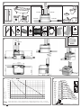
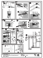
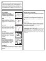
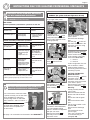
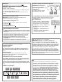
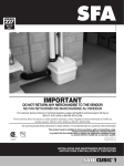
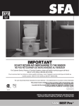
226
1
10.12
IND1
IMPORTANT
DO NOT RETURN ANY MERCHANDISE TO THE VENDOR
NE PAS RETOURNER DE MARCHANDISE AU VENDEUR
For Customer Service, Returns or Technical Questions, please call Saniflo’s technical support toll-free at
800-571-8191 (USA) or 800-363-5874 (CDN).
Pour le service client, les retours ou toute question technique, merci d’appeler le service technique de Saniflo au
numéro suivant : 800-571-8191 (USA) ou 800-363-5874 (CDN).
The user should retain these instructions for future reference • A lire attentivement et à conserver à titre d’information
This product must be installed in strict accordance with local plumbing codes.
Product should be installed by a licensed plumber.
Le produit doit être installé dans le respect des règlements sanitaires locaux.
Le produit doit être installé par un plombier qualifié.
226615
CDN USA
INSTALLATION AND MAINTENANCE INSTRUCTIONS
INSTRUCTIONS D’INSTALLATION ET D’ENTRETIEN
1-1/2”
1-1/2”
1
1-1/2”/4”
1-1/2”/4”
1-1/2”/4”*
1-1/2”/4”*
2
A
x2
B
x2
C
x8
D
x4
E
40/60
x2
F
x2
G
x2
H
x2
x4
J
x1
K
x2
L
O
x1
10/16
100/120
32/50
N
3
x1
6 feet
*
*
7
6
P1
Vertical Height (feet)
Hauteur (feet)
33
30
27
24
21
18
15
12
9
6
3
0
P1+P2
1%
maxi 36 Ft
29 Ft
1%
23 Ft
1%
19 Ft
1%
16 Ft
1%
13 Ft
1%
10 Ft
6 Ft
25
30
35
40
45 50
55
60
65
70 75
80
OK
maxi 98 Ft
SFA
maxi 131 Ft
maxi 164 Ft
maxi 197 Ft
maxi 229 Ft
SFA
maxi 262 Ft
maxi 295 Ft
1%
maxi 328 Ft
1%
3 Ft
20
8b
1%
26 Ft
maxi 360 Ft
85 90
P1
Flow Rate with 1 motor (gallons/min.) Débit (gallons/min.) avec 1 moteur
P1+P2 Flow Rate with 2 motors (gallons/min.) Débit (gallons/min.) avec 2 moteurs
* cf.
maxi 65 Ft
1%
1%
SFA
8
8d
8b
D
3
1
D
1-1/2’’
2
8e
J
1
2
3
J
J
F
J
F
8f
8g
2
1
1
C
D
3
N
C
O
2
8h
L
SFA
B
H
G
L
L
A
9
SANICUBIC® 2
Société Française d’Assainissement
EN 12050-1
R300 LC
220-240 V - 60 Hz
2 x 1 HP -
226615
The numbers refer to the explanatory diagrams.
1 DESCRIPTION
6 PERFORMANCE CURVE
®
The SANICUBIC 2 is a lifting station designed to evacuate effluent from small private
or commercial units.
Please comply with all the installation and
maintenance specifications set out in these
instructions, and especially the information
marked with the following signs:
«
» Failure to comply with this
information could entail safety
hazards for personnel,
«
» Information warning of the presence of an electrical hazard,
«
» Instructions only for qualified
professional specialists,
«WARNING» Failure to comply with this
information could affect the normal
operation of the equipment.
Please contact our Customer service for
further information.
SANICUBIC OPERATING
PRINCIPLE
SANICUBIC® 2 contains 2 separate pumps.
Each of the pumps is fitted with a high-performance macerating system.
The 2 pumps operate alternately. In the
event of inflow overload, both motors run
at the same time (or if one of the pumps
is faulty, the other one takes over).
The SANICUBIC® 2 tank is fitted with 2 dip
tubes; one tube controls motor
operation, and the other one controls the
alarm system.
- Long pickup tube (normal operation):
as soon as the waste water level in the
tank reaches the triggering point in the
long tube, the pumping system starts up.
- Short pickup tube (inflow overload
operation): if the waste water level in the
tank reaches the upper point, a contact is
closed, and the auxiliary pumping system
is triggered. The contact also sets off an
visual alarm. The general alarm LED on
the SANICUBIC® 2 control panel switches
to red.
2 LIST OF PARTS SUPPLIED
3 DIMENSIONS
4 TECHNICAL DATA
SANICUBIC® 2
Type
Maximum discharge head
Voltage
Frequency
Volume
Maximum power input
Maximum current input
Electrical classification
Ave water temp for optimum performance
Maximum temperature (intermittent)
Protection index
Net weight (including accessories)
R300 LC
36 Ft
220-240V
60 Hz
12 Gallons
2 x 1 HP
13 A
I
104 F
160 F*
IP67
66 Lbs
*Hot water drain cycles from dishwashers or washing machines
Example: Pump P1 is operating normally.
It discharges 38 gpm at a pumping height
of 16 Ft. If pump P1 shows any signs of
weakness or if the waste water inflow is
too great, pump P2 starts up. The output
is then increased to about 64 gpm, until
the situation returns to normal.
8c
If you want to install a shower or
a bath at the same level as the
SANICUBIC® 2, you must make
sure that the upper parts of the plugholes on the sanitary equipment are at
least 10’’ above the lower inlets.
7 RATIO OF HEIGHT/LENGTH
FOR DISCHARGE
8d
8 INSTALLATION
The SANICUBIC® 2 must be
installed in compliance with local plumbing
codes. The equipment must be
commissioned and maintained by a
qualified professional specialist.
REGULATIONS
1- Attention: the space in which the
SANICUBIC® 2 is to be installed must
be large enough to leave at least 24’’
of working room around and above the
unit to facilitate such maintenance work
as may be required. There must be sufficient lighting, and it must be
sufficiently well ventilated and protected
from freezing.
2- Isolating valves (not supplied) must
be fitted on waste inlets (especially
the 4’’ inlets) and on the discharge
to ensure that any service/maintenance may be carried out safely).
3- The discharge pipe must be fitted so as
to avoid all back flow from the drainage
system (see the examples in drawing
8g ). Back flow can be avoided by
installing an anti-back flow riser
reaching a high point above the
maximum back flow level.
Comment: In the absence of local
information to the contrary, the
maximum back flow level corresponds
to street level (roadway, pavements,
etc.). Continue the discharge pipework
after the anti-backflow riser, using a
larger diameter pipe.
4- If the Sanicubic is installed in a space
such as a pit for example, we would
recommend the fitting of a bilge pump
in case of flooding.
5- The lifting station must be vented with
an outlet at roof level.
6- The lifting station must be fixed to the
floor (see 8h ).
CONNECTING SANITARY
EQUIPMENT TO THE LOWER
INLETS
CONNECTING THE INLETS 1-1/2’’
Lower inlets (cf. 8d 1 )
Upper inlets (cf. 8d 2 )
• Cut off the end of the 1-1/2’’ inlet with a
saw
• Cut the sleeve D to suit the pipe
diameter: 1-1/4’’ or 1-1/2’’ (cf. 8d 3 )
• Fix the sleeve D on the inlet and on the
pipe, using the collars.
8a
8b CONNECTING THE DISCHARGE PIPE
Remove the end cover or covers from the
back of the unit (cf. 8g 1 ).
As each pump is fitted with a macerator
system, an 1-1/2’’ discharge pipe can be
used.
The discharge bend is at the centre of the
unit, at the back (cf. 8b). Use a standard
1-1/2’’ coupling (not provided) to connect
it to the riser pipe and fix it in place with
metal clamps.
Each pump in the SANICUBIC® 2 unit is
fitted with check valves.
8e CONNECTING THE 4’’ INLET
Lower inlets (cf. 8e 1 )
1- Remove the plug from the side inlet.
2- Fix the sleeve F in place using the
collar. J .
3- Fully insert the 4’’ tube in the other end
of the sleeve and fix it in place using
the other collar. J .
Upper inlets (cf. 8e 2 )
1- Cut off the upper end of the 4’’ inlet
with a saw.
2- Fix the sleeve F in place using the
collar J .
3- Fully insert the 4’’ tube in the other end
of the sleeve and fix it in place using
the other collar J .
8f CONNECTING THE VENT
1- VENT OF SANICUBIC® 2
One of the upper 1-1/2’’ inlets must
be used for the vent. The vent pipe
must be fitted up to roof level.
Cut off the end of the one of the
1-1/2’’ inlets with a saw.
Then fix the sleeve D in place using
the collar C .
Fully insert the 1-1/2’’ tube in the
other end of the sleeve and fix it in
place using the other collar C .
WARNING: Note that the vent
system should be a two-way air vent.
The use of mechanical vents, air
admittance valves or similar devices
are not permitted as these are considered one-way air vent systems.
The vent must be an open vent or
the unit will not operate.
2- VENTING THE ELECTRICAL PART
Connect the 8/11 clear PVC tubing ( N )
supplied to the keyboard on the
Sanicubic. The other end of this
tubing must be located between 3 Ft
and 6 Ft above the device to avoid
water getting into the electrical part
in the event of flooding.
Important: do not pinch the tubing.
DRAINING
The SANICUBIC® 2 unit is fitted with 2 plugs (8g 1 ).
Disconnect the unit from the power supply.
To drain the unit
1- Unclip the cover.
2- Remove one of the 2 plugs.
3- Insert a wet utility vacuum cleaner pipe to drain the unit. The
port diameter is 1-1/2’’.
4- When the unit has been drained, put
the plug and then the cover back in place.
8g
FIXING THE SANICUBIC UNIT TO THE FLOOR
The SANICUBIC® 2 unit is equipped with fittings to hold it on the
floor and prevent it from turning or moving.
8h
1- Place the unit on the desired spot.
2- Draw the outline of the unit.
3- Position the brackets and fix them to the floor as shown on the
template diagram (8h 1 ).
4- Put the unit back in place.
5- Fix the unit in place with the screws.
8i ELECTRICAL CONNECTIONS
1- The electrical installation work must be carried out by a
qualified electrician.
The electrical installation must comply with the standards in
force in the country concerned
2- The power supply must be of the class 1 type. The unit must
be connected via an earthed connection box. The electric
power circuit must be protected by a high-sensitivity 30 mA
differential circuit breaker set at 20 A. The connection must
be used solely to power the SANICUBIC® 2. If the power lead
on the unit is damaged, it must be replaced by the manufacturer or its after-sales service to avoid all danger.
EXTERNAL WIRED ALARM
REMOTE ALARM MODULE
The external alarm box of the
SANICUBIC® 2 does not require
an independent power supply.
It is powered via the circuit board
of the SANICUBIC® 2.
In the case of a power outage,
a battery takes over.
red
general
alarm
LED
yellow
power
alarm
LED
CONNECTING THE ALARM BOX
Connect the alarm cable directly to the
control panel. The cable can extend for
15 Ft for ease of installation.
1/ The red LED on the alarm box goes off
(visual and audible) at the same time that
the LED on the mounted control panel does.
2/ The yellow “power” LED shows the status
of the power supply for the alarm box :
- LED on: normal power
- LED flashing: power supply is faulty.
10 CONFORMITY WITH STANDARDS
• SANICUBIC® 2 is eligible to bear the CSA mark shown with adjacent indicators “C” and “US”. The “C” and “US” indicators adjacent to the CSA mark signify that the product has been
tested according to the applicable CSA (CAN) and ANSI/UL
standards for use in Canada and the USA. This includes products eligible bear the designation NTRL. NTRL (Nationally
Recognized Testing Laboratory) is a designation awarded by
the American Occupational Safety and Health Administration
(OSHA) to laboratories authorized to award the certification
according to American standards.
11 COMMISSIONING
9 ALARM OPERATION
1/ General alarms:
High level alarm:
If the water level in the unit is abnormally high: the red LED
comes on; the other motor starts up 3 seconds later (see the
illustration showing the control keyboard).
Temporary alarm:
If one of the 2 motors runs for more than 1 minute: the red
alarm LED comes on; the other motor starts up 3 seconds later.
2/ Resetting the general alarms:
If the problem that has triggered one of the alarms referred to
above ceases, the red alarm LED stays on to memorize the
fact that the system has met with a problem.
The “Reset alarm” key on the keyboard switches the red LED
off if the problem that triggered the alarm has been dealt with.
This avoids the risk of having a system “abandoned” in fault
status.
UNIT ALARM
motor 1
LED
motor 2
LED
“Alarm”
LED
“Mains”
LED
1- Once the plumbing and electrical connections have been
made, check that the connections are watertight by
letting water flow successively through each inlet used.
Make sure that the unit is operating correctly by carrying out
at least two start cycles with water to test the system.
2 - WARNING! Do not operate the motors in override status
(by pressing the pushbuttons on the control box) until
the pumps have been filled with water. Operation without
water damages the macerating system.
3 - This device is not designed for persons (including
children) with limited physical, sensory or mental
abilities, or those with minimal experience and
knowledge, unless they are monitored and are given the
necessary instructions for using the device,
with the help of a person responsible for their safety.
Monitor children and make sure they do not play
with the device.
12 USE
1- The SANICUBIC® 2 unit is designed to drain off waste water.
Any other use will invalidate the warranty. It is not recommended to dispose sanitary towels, condoms or hygiene
articles through the unit. The disposal of oils,
solvents, acids or any other potentially corrosive or
explosive liquids, etc. is prohibited.
2- WARNING: In the event of a power failure, stop
draining any water from the equipment connected
to the SANICUBIC® 2 unit.
motor 1
“Override”
motor 2
“Override”
“RESET”
Alarm
3- Do not install or use the unit in a zone where there is a
risk of explosion.
13 MAINTENANCE
A visual check of the lift station must be made once a month
to make sure it is operating correctly, and the installation must
be inspected regularly (once a year) by a qualified person.
Meanwhile if encounter technical problems, please ask our
after-sales service for advice. If the power supply cable of the
unit is damaged, it must be replaced by the manufacturer or its
after-sales service to avoid all danger.
14 ADVICE
PIPE SUPPORTS
All sanitary pipe work must be
supported, in accordance with the pipe
manufacturer’s recommendations.
Avoid dipping or trapping, which may
cause the build up of residual “solids”
and sub- sequent blockage.
BENDS
Where possible long sweeping bends
should be used. Do not use short
elbows. If sweeping 90° elbows are not
available use two 45° elbows to make a
90° turn.
PIPE WORK
All pipe work should be either copper,
PVC or CPVC (Do not use flexible
pipes). Hangers should not be less than
four feet apart to prevent pipe rattling.
DISCHARGE
Never discharge directly into an open
drain, fixture, manhole or rainwater
drainpipe. It is illegal for it constitutes a
health hazard. Direct connections into
sanitary waste systems only, shall be
acceptable.
FREEZING
Ensure all pipe work susceptible to
freezing is adequately insulated or
heated. In unheated buildings, the toilet,
piping and macerating unit must be
properly winterized with “RV or
plumbers” anti-freeze or drained
completely.
ELECTRICITY
Before attempting any maintenance or servicing, the unit must
be disconnected from the power source. The macerating
system must be connected to a Ground Fault Circuit
Interrupter.
VERTICAL INSTALLATION FIRST
If vertical lift is required, this must precede the horizontal pipe
run.
EASY ACCESS
The unit should be accessible and removable in the event
of maintenance being required. During the installation a fullport ball valve should be installed at the base of any vertical
discharge pipe work from the unit to allow easy service of the
unit.
GRAVITY FALL
The unit accepts wastewater by gravity; it does not “vacuum”
in water. All inlet pipe work must have a positive gravity fall,
(1/4» per foot). All horizontal piping from the macerating unit
must also have a positive gravity fall to allow free
drainage when the pump stops.
NO DIAGONAL “UPHILL” PIPE RUNS
All discharge pipe work from the unit should run either directly
vertical upwards from it or in a horizontal plane (with a small
gravity flow) to the point of discharge. Pipe work should not
be
installed with diagonal upward slope from the unit to the point
of discharge.
Page 6
INSTRUCTIONS ONLY FOR QUALIFIED PROFESSIONAL SPECIALISTS
15 WORK THAT MAY BE REQUIRED
REMOVING A MOTOR
DISCONNECT THE UNIT FROM THE POWER
SUPPLY (the yellow indicator light must be off).
ELECTRICAL INSTALLATION MUST BE CARRIED
OUT BY A PROFESSIONAL ELECTRICIAN
Before carrying out any other types of work, disconnect
the SANICUBIC® 2 from the power supply.
UNIT ALARM
The unit beeps to show that it
is no longer under power.
A
Possible preliminary maintenance operations on the unit
PROBLEM
PROBABLE CAUSES
No motor starts and the mains No power
yellow LED is off (*)
SOLUTIONS
Check your electrical
connections
G
16 2
The LED warning light is on
1 – Obstructed pumps
2 – Blocked up pumps
1 – Press the override button
continuously to get the
pumps working
Possible secondary maintenance operations
PROBLEM
PROBABLE CAUSES
1 – Faulty electronic card
2 – Faulty detection system
1 – Contact SFA after-sales
service
Pumps running continuously
1 – Obstructed discharge pipe
1 – Remove obstruction from
the discharge pipe
2 – Check installation (**)
Alarm activated
Pumps starting up
intermittently
1 – Obstructed pumps
1 – Blocked pumps
3 – Electrical motor problems
4 – Excessive inflow of water
5 – Faulty electronic card
1 – The non-return valves are
leaking or broken
2 – Faulty electronic card
Unclip the cover.
Unscrew the collar A on the
faulty motor (the check valve
stays in place while the motor
is being repaired).
SOLUTIONS
The motor does not start
but override works
2 – Pump discharge height
too high
3 – Faulty electronic card
16 6
3 – Contact SFA after-sales
service
1 – Contact SFA after-sales
service
B
Operations on the electronic
board (cf. illustration 16 1 ):
set the switch corresponding
to the number of the faulty
motor from ON to OFF:
1 = motor 1
2 = motor 2
In this configuration, the unit
will not switch to “alarm”
status and the electronic
board only powers the motor
remaining in place.
C
16 3
Unscrew the collar B .
Remove the motor power
wires C from the screw
connector.
1 – Clean or change the valves
2 – Contact SFA after-sales
service
(*) A flashing yellow LED indicates that there has been a power cut.
Pressing one of the two motor override buttons will stop the LED flashing.
(**) Warning: if pumping height is high, 90° elbows should be avoided.
PUTTING THE MOTOR
BACK IN PLACE
E
D
16 4
16 DISMANTLING
INSTRUCTIONS RESERVED EXCLUSIVELY FOR
QUALIFIED PROFESSIONAL SPECIALISTS
If one of the motors cannot be made
to operate correctly, use of that motor
can be “disabled” by setting the
corresponding switch on the board
(SW1: switches 1 and 2 for motors 1
and 2).
The motor thus “disabled” can be
removed. The unit operates on
the other motor.
16 1
See page 7 for connections to the board of the SANICUBIC® 2
Put the inspection cover
back in place.
Reconnect the discharge
pipe.
Use the plug G to close off
the motor cable outlet in the
inspection cover. Fix using
the hose clip B .
Remove the screws D from
the inspection cover.
Use the handle E to lift the
motor carefully.
Remove the plug G and the
inspection cover.
Screw the motor onto the
inspection cover and put the
cover back in place.
Reconnect the motor power
wires (cf. illustration 16 3 ).
Warning:
Comply carefully with the
colour code:
Blue wire with the blue wire
Brown wire with the brown
wire
Green wire with the green
F
wire
White wire with the white
16 5
wire
Set the motor switch on the
If the faulty motor has to be
board to ON.
sent back to the manufacturer,
Reconnect the discharge
you can operate the lifting
pipe.
station in minimum configuration Connect the unit to the
with just one motor.
power supply.
Remove the screws F of
Carry out a complete test
the faulty motor from the
for commissioning (cf.
paragraph 11).
inspection cover.
BOARD SANICUBIC® 2 / CARTE SANICUBIC® 2
Page 7
3
1
2
4
5
11
7
6
7
12
8
8
9
10
13 14 15
Each marked cable lug must be
isolated (9, 10, 11 and 12)
Attention : chaque cosse marquée
doit être isolée (9, 10, 11 et 12)
1 Brown: alarm pressure switch x2
Marron : pressostat alarme x2
2 Brown: level pressure switch x2
Marron : pressostat niveau x2
3 Brown: power cord
Marron : cordon alimentation
4 Blue: motor 1
Bleu : moteur 1
5 Blue: motor 2
Bleu : moteur 2
6 Blue: power cord
Bleu : cordon alimentation
7 White: motor running capacitor 1
Blanc : condensateur moteur 1
8 White: motor running capacitor 2
Blanc : condensateur moteur 2
9 Brown: motor 1
Marron : moteur 1
10 Brown: motor 2
Marron : moteur 2
11 White: motor 1
Blanc : moteur 1
12 White: motor 2
Blanc : moteur 2
13 Green/yellow: motor 1
Vert/jaune : moteur 1
14 Green/yellow: motor 2
Vert/jaune : moteur 2
15 Green/yellow: power cord
Vert/jaune : cordon alimentation
LIMITED WARRANTY
Warranty period two-year from date of purchase
Subject to the conditions listed below, SFA-SANIFLO INC. (hereinafter called the «Company»)
guarantees to repair or at its option replace the product or any component thereof, which, in the
opinion of the Company, is faulty or below standard as a result of inferior workmanship or materials.
If replacement is to be issued, this will only be extended to the first year starting from the date of
purchase. Warranty repairs will apply after such date up to the warranty’s date of conclusion.
CONDITIONS
The conditions of this guarantee are:
1.The product must not have been subjected to misuse, neglect, accident or damaging
products, in accordance with the paragraph «USAGE» of these Installation Instructions.
2.The product must be connected to the proper electrical supply as per the installation
manual.
3.The alleged fault or defect must be notified to the company, within the warranty period.
PART OR PRODUCT EXCHANGE
The product will be exchange, free of charge, at the original resellers place of business only, upon
the followings conditions being fullfilled:
1 The customer need a «return authorization» number from the company to authorize and
validate the exchange.
2 The customer must supply a copy of their invoice to validate the request for an exchange.
LIMITATIONS
1.Cost of disconnection and reconnection (ie labor charges) are not covered by the warranty
and are end-users responsability.
2.Cost of mail or freight when a part or parts of the system have to be repaired at the
company are not covered by this warranty.
3.In no event shall the company be reliable for any special, incidental or consequential
damage, loss, or injury of whatsoever nature or kind arising from or in connection with the
product or any component thereof.
4.The guarantee is transferable only when the product remains at the same premises as
where it was installed initialy.
Except as set forth in this Limited Warranty, the company disclaims all other warranties, express or
implied, with respect to the product or any component thereof including, but not limited to, all implied
warranties for merchantability and fitness for a particular purpose
For service or for further inquiries, please call or contact any of the following addresses:
United States
SFA-SANIFLO INC.
105 Newfield Avenue, Suite A
Edison, NJ 08837
Canada
SFA-SANIFLO INC.
1-685 Speedvale Avenue West
Guelph ON
N1K 1E6
Toll Free:
1-800-571-8191
Telephone:
Fax:
E-mail.:
Web Site:
1-732-225-6070
1-732-225-6072
[email protected]
www.saniflo.com
Toll Free:
Toll Free:
Telephone:
Fax:
E-mail.:
Web Site:
1-800-363-5874 English
1-800-877-8538 French
1-519-824-1134
1-519-824-1143
[email protected]
www.saniflo.ca
Les numéros renvoient aux schémas explicatifs
6 COURBE DE PERFORMANCES
1 DESCRIPTIF
®
SANICUBIC 2 est une station de relevage
conçue pour évacuer les effluents de
petites unités à usage privé ou commercial.
Respecter toutes les règles d’installation
et d’entretien décrites dans cette notice.
En particulier les indications repérées par :
» indication dont le non-respect
«
pourrait entraîner des risques pour
la sécurité des personnes,
» indication avertissant de la
«
présence d’un risque d’origine
électrique,
» instructions réservées exclusive«
ment aux professionnels qualifiés,
«ATTENTION» indication dont le
non-respect pourrait entraîner des
risques pour le fonctionnement de
l’appareil.
Pour tous renseignements complémentaires, veuillez vous adresser à notre
service clients.
PRINCIPE DE FONCTIONNEMENT
SANICUBIC® 2 contient 2 pompes indépendantes. Chacune de ces pompes est
équipée d’un système de dilacération haute
performance.
Les 2 pompes fonctionnent chacune à leur
tour de manière alternée. En cas de
fonctionnement anormal, les 2 moteurs
fonctionnent simultanément (ou si l’une
des pompes est défectueuse, l’autre prend
le relais).
La cuve du SANICUBIC® 2 est munie de
2 tubes plongeurs qui commandent l’un
la marche des moteurs, l’autre le système
d’alarme.
- Tube plongeur long (fonctionnement
normal) : dès que les effluents atteignent
le niveau d’enclenchement du tube long
dans la cuve, le système de pompage se
met en marche.
- Tube plongeur court (fonctionnement
anormal) : si les effluents atteignent le
niveau haut dans la cuve, un contact est
établi, une marche forcée du système de
pompages auxiliaires est enclenchée.
Ce contact déclenche une alarme visuelle.
La LED de l’alarme générale sur le clavier du SANICUBIC® 2 devient rouge.
2 LISTE DES PIECES FOURNIES
3 DIMENSIONS
Exemple: La pompe P1 travaille
normalement. A 16 Ft de refoulement elle
évacue 38 gpm. A la moindre insuffisance
de la pompe P1 ou lors d’une arrivée
d’eaux usées trop importante, la pompe
P2 se met en marche. Le débit monte
alors à environ 64 gpm, jusqu’à
normalisation.
7 EQUIVALENCE HAUTEUR/
LONGUEUR EVACUATION
8 INSTALLATION
La mise en service et la maintenance de
cet appareil doivent être effectuées par un
professionnel qualifié.
8a RÉGLEMENTATION
1- Attention : le local technique où sera
installé SANICUBIC® 2 doit être de
dimension suffisante pour aménager
un espace de travail de 24’’ minimum
autour et au-dessus de l’appareil de
façon à faciliter une maintenance
éventuelle. Ce local doit être éclairé,
suffisamment ventilé et protégé contre
le gel.
2- Des vannes d’arrêts (non fournies)
doivent être installées sur les
entrées d’effluents ainsi que sur
la conduite d’évacuation.
3- Cette conduite d’évacuation doit être
conçue pour éviter tout reflux des
égouts (voir exemples dessin 8g 3 ).
Grâce à l’installation d’une boucle
anti-retour, située au-dessus du niveau
de reflux, le reflux est évité.
Remarque : Sauf indications locales
contraires, le niveau de reflux
correspond au niveau de la voirie
(routes, trottoirs…). Continuez ce
conduit après la boucle anti-retour par
le tuyau d’un diamètre supérieur.
4- L’installation d’une pompe auxiliaire
pour le drainage éventuel du local
technique (en cas d’inondation) est
recommandée.
5- La station de relevage doit être aérée
par-dessus le toit.
6- La station de relevage doit être fixée au
sol (voir 8h ).
4 DONNEES TECHNIQUES
SANICUBIC® 2
Type
Hauteur de refoulement maximum
Tension
Fréquence
Volume
Puissance absorbée maximale
Intensité absorbée maximale
Classe électrique
Température moyenne
des eaux admissibles
Température maximum
(par intermittence)
Indice de protection
Poids net (accessoires inclus)
R300 LC
36 Ft
220-240V
60 Hz
12 Gallons
2 X 1 HP
13 A
I
104 F
160 F*
IP67
66 Lbs
*Cycles d’évacuation chaude de lave-vaisselle et lave-linge
RACCORDEMENT DE
L’EVACUATION
Déposez le ou les cache-embouts à
l’arrière de l’appareil (cf 8g 1 ).
Grâce au système de dilacération qui
équipe chaque pompe, la conduite
d’évacuation peut être réalisée avec un
tuyau 1-1/2’’.
Le coude de refoulement se trouve au
centre de l’appareil, à l’arrière (cf 8b).
Reliez-le par un manchon standard de
1-1/2’’ (non fourni) au tuyau ascendant et
fixez-le avec les colliers métaliques.
Chaque pompe du SANICUBIC® 2 est
équipée de clapets anti-retour.
8b
8c
RACCORDEMENT D’APPAREILS
SANITAIRES AUX ENTRÉES
BASSES
Si vous souhaitez installer une
douche ou une baignoire au
même niveau que le SANICUBIC®
2, vous devez impérativement veiller à
placer la partie supérieure des bondes
d’évacuation des appareils à une hauteur minimum de 10’’.
8d RACCORDEMENT ENTRÉES 1-1/2’’
Entrées basses (cf 8d 1 )
Entrées hautes (cf 8d 2 )
• Découper l’extrémité de l’entrée 1-1/2’’
avec une scie
• Découper le manchon D au diamètre du
tuyau : 1-1/4’’ ou 1-1/2’’ (cf 8d 3 )
• Fixer le manchon D sur l’entrée et sur le
tuyau à l’aide des colliers.
8e RACCORDEMENT DE L’ENTRÉE 4’’
Entrées basses (cf 8e 1 )
1- Enlever le bouchon de l’entrée latérale.
2- Fixer le manchon F avec le collier J .
3- Enfoncer le tube 4” dans l’autre
extrémité du manchon et le fixer avec
l’autre collier J .
Entrées hautes (cf 8e 2 )
1- Découper l’extrémité haute de l’entrée
4’’ avec une scie.
2- Fixer le manchon F avec le collier J .
3- Enfoncer le tube 4’’ dans l’autre
extrémité du manchon et le fixer avec
l’autre collier J .
8f RACCORDEMENT DE L’EVENT
1- EVENT DU SANICUBIC® 2
Une des entrées hautes 1-1/2’’ doit
être dédiée à la ventilation.
La conduite d’aération doit être liée
au toit.
Découper l’extrémité d’une des
entrées 1-1/2’’ avec une scie.
Puis fixer le manchon D avec le
collier C .
Enfoncer le tube 1-1/2’’ dans l’autre
extrémité du manchon et le fixer
avec l’autre collier C .
ATTENTION : N’utilisez pas une
vanne d’admission d’air ni un event
a ressort car ces mécanismes sont
a sens uniques. La pression d’air
doit demeurer uniforme a l’intérieur
et a l’extérieur de l’ensemble
broyeur-pompe.
2- MISE À L’AIR DE LA PARTIE
ÉLECTRIQUE:
Connecter le tuyau PVC cristal 8/11
( N ) fourni au clavier situé sur le
Sanicubic. L’autre extrémité de ce
tuyau doit se situer entre 3 FT et 6 Ft
au-dessus de l’appareil pour éviter
que l’eau rentre dans la partie
électrique en cas d’inondation.
Attention : ne pas pincer le tuyau.
8g VIDANGE
Le SANICUBIC® 2 est muni de 2 bouchons ( 8g 1 ).
Débrancher l’alimentation électrique de l’appareil
1- Déclipser le capot.
2- Enlever 1 des 2 bouchons.
3- Passer le tuyau d’aspirateur (à eau) pour vidanger l’appareil.
Le diamètre de passage est de 1-1/2’’.
4- Une fois la vidange terminée, replacer le bouchon puis le
capot.
8h
FIXATION AU SOL DE LA CUVE
SANICUBIC® 2 possède des dispositifs de fixation au sol
l’empêchant de tourner ou de bouger.
1- Placer l’appareil à l’endroit souhaité.
2- Tracer le contour de l’appareil.
3- Positionner et fixer au sol les équerres selon le plan de
perçage ( 8h 1 )
4- Replacer l’appareil.
5- Fixer l’appareil avec les vis B .
RACCORDEMENT ÉLECTRIQUE
1- L’installation électrique doit être réalisée par un électricien qualifié.
L’installation électrique doit correspondre aux normes en vigueur
dans le pays.
2- L’alimentation doit être réalisée en classe 1. L’appareil doit être
raccordé à un boîtier de connection relié à la terre. Le circuit
d’alimentation électrique doit être protégé par un disjoncteur
différentiel haute sensibilité de 30 mA calibré à 20 A.
Ce raccordement doit servir exclusivement à l’alimentation du
SANICUBIC® 2.
Si le câble de cet appareil est endommagé, il doit être
remplacé par le fabricant ou son SAV afin d’éviter tout danger.
8i
9 FONCTIONNEMENT DE L’ALARME
1/ Alarmes générales :
Alarme de niveau :
Si le niveau d’eau à l’intérieur de l’appareil est anormalement
haut : allumage de la LED rouge alarme + démarrage de
l’autre moteur 3 secondes après (voir visuel clavier de commande).
Alarme temporelle :
Si un des 2 moteurs marche pendant plus de 1 minute :
allumage de la LED rouge alarme + démarrage de l’autre
moteur 3 secondes après.
MODULE D’ALARME À DISTANCE DÉPORTÉ
Le boîtier d’alarme déporté du
SANICUBIC® 2 ne nécessite pas
d’alimentation indépendante.
Il est alimenté par la carte de circuit
du SANICUBIC® 2.
En cas de coupure de courant,
l’accumulateur prend le relais.
red
rouge
general
alarme
alarm
générale
LED
DEL
yellow
jaune
power
alarme
alarm
générale
LED
DEL
RACCORDEMENT DU BOÎTIER D’ALARME À L’APPAREIL
Connecter le câble d'alarme directement au boîtier.
Le SANICUBIC® 2 est livré avec 15 FT de câble
pour le boîtier alarme.
1/ La DEL rouge de « l’alarme générale »
reproduit le fonctionnement de la DEL
correspondante sur la carte de base.
2/ La DEL jaune « réseau » indique l’état
de l’alimentation du boîtier d’alarme
à distance :
- Allumée fixe = module alimenté par
le réseau.
- Clignotante = défaut d’alimentation
du réseau pour le module.
10 CONFORMITE AUX NORMES
• SANICUBIC® 2 satisfait aux conditions requises pour
porter la CSA Mark Shown, avec les sigles adjoints «C» et
«US». Les sigles «C» et «US» adjoints à la CSA Mark signifient que le produit a été évalué d’après les normes CSA (CAN)
et ANSI/UL applicables pour une utilisation sur le territoire du
Canada et des Etats-Unis. Ceci inclut les produits satisfaisant
aux conditions requises pour porter la mention NTRL.
La mention NTRL, Nationally Recognized Testing Laboratory
(laboratoire d’essai reconnu nationalement), est une appellation
décernée par la Occupational Safety and Health Administration
(OSHA) (Agence pour la sécurité et la santé au travail) américaine
aux laboratoires comme ayant l’autorité d’accorder la certification
selon les normes américaines.
2/ RAZ (Remise A Zéro) alarmes générales :
Si le problème ayant déclenché une des alarmes ci-dessus disparaît, la LED rouge d’alarme reste allumée pour mémoriser le
fait que le système a rencontré un problème.
La touche “RAZ alarme” du clavier ne permettra d’éteindre la
LED rouge que si le problème ayant déclenché l’alarme a été
résolu. Ceci permet d’éviter qu’un système soit “abandonné” en
défaut.
ALARME DE L’APPAREIL
LED
moteur 1
LED
moteur 2
“marche
forcée”
mot 1
LED
“Alarme”
“marche
forcée”
mot 2
LED
“secteur”
“RAZ”
Alarme
11 MISE EN SERVICE
1- Une fois les raccordements hydrauliques et électriques
effectués, vérifier l’étanchéité des raccordements en laissant
couler de l’eau successivement par chaque entrée utilisée.
S’assurer du bon fonctionnement de l’appareil en effectuant
un essai en eau de 2 cycles de démarrage au minimum.
2- ATTENTION : ne pas faire fonctionner les moteurs en
marche forcée (en appuyant sur les boutons poussoirs
du boîtier) avant d’avoir mis les pompes en eau. Un
fonctionnement à sec détériore le système de broyage.
3- Cet appareil n’est pas destiné aux personnes (y compris
les enfants) dont les capacités physiques, sensorielles
ou mentales sont limitées, ou auxquelles l’expérience et
les connaissances font défaut, excepté si elles sont sous
surveillance et reçoivent les instructions nécessaires
pour utiliser l’appareil, avec l’aide d’une personne
responsable de leur sécurité. Surveiller les enfants
et veiller à ce qu’ils ne jouent pas avec l’appareil.
12 UTILISATION
13 MAINTENANCE
1- SANICUBIC® 2 est conçu pour évacuer les eaux usées d’origine domestique. Toute autre application entraînerait l’annulation de la garantie.
Ne jamais rejeter serviettes, préservatifs, articles d’hygiène,
huiles, solvants, déchets, acides, bases, autres liquides
potentiellement explosifs, corrosifs…
Le bon fonctionnement de la station de relevage doit être vérifié
visuellement une fois par mois et doit régulièrement être
contrôlé par un personnel qualifié (annuellement). Si toutefois
vous rencontriez des problèmes techniques, demandez conseil
au service après-vente. Si le câble de cet appareil est
endommagé, il doit être remplacé par le fabricant ou son
service après vente pour éviter tout danger.
2- ATTENTION : En cas de coupure de courant, arrêter
tout écoulement d’eau sur les appareils reliés au
SANICUBIC® 2.
3- Ne pas installer/utiliser dans une zone à risque
d’explosion.
14 CONSEILS
ANCRAGE DES TUYAUX
LA TUYAUTERIE VERTICALE D’ABORD
Tous les tuyaux des installations sanitaires doivent être ancrés conformément
aux recommandations du fabricant
pour les empêcher de pendre, car ils
pourraient alors être bloqués par une
accumulation de “matières solides ”.
Lorsqu’on installe des tuyaux à la verticale, il faut les poser avant
de poser les tuyaux horizontaux.
COURBES
Dans la mesure du possible, utilisez des
courbes de tuyau plutôt que des coudes.
Si des coudes de 90° ne sont pas
disponibles, utilisez deux coudes de 45°
pour former une courbe de 90°.
TUYAUTERIE
Tous les tuyaux doivent être en cuivre ou
en plastique soudé au solvant. Il ne faut
pas utiliser de tuyaux flexibles.
Les pendards doivent être espacés d’au
moins quatre pieds pour empêcher les
tuyaux de cogner.
VIDANGE
Ne jamais évacuer les eaux usées
directement dans un égout à ciel ouvert,
un trou d’homme ou un drain pour les
eaux de pluie. Cela est illégal et constitue
un danger pour la santé. Seuls les
branchements directs dans les systèmes
de déchets sanitaires sont acceptables.
GEL
Assurez-vous que tout tuyau susceptible
de geler est bien isolé ou chauffé. Dans
les immeubles non chauffés, la toilette, la
tuyauterie et l’ensemble broyeur-pompe
doivent être protégés contre le gel avec
de l’antigel de « véhicule de plaisance »
ou vidés complètement.
ELECTRICITÉ
Avant d’entreprendre des travaux d’entretien ou de dépannage, il
faut débrancher l’appareil de la source d’alimentation en électricité.
Le système de broyage doit être protégé par un coupe-circuit en
cas de défaut de mise à la terre du neutre.
ACCÈS FACILE
Il faut avoir accès à l’ensemble broyeur-pompe et pouvoir le
déposer en cas de réparation. Au moment de l’installation, il faut
poser une purge et une vanne d’arrêt à passage intégral à la
base de tout tuyau d’évacuation vertical, pour permettre de
réparer facilement l’appareil.
DESCENTE PAR GRAVITÉ
Les eaux usées se déversent dans
l’ensemble broyeur-pompe par gravité. Elles ne sont pas
aspirées. Tous les tuyaux d’arrivée doivent assurer l’écoulement
absolu par gravité (1/4 po par pied). Les tuyaux d’évacuation
horizontaux
sortant de l’ensemble broyeur-pompe
doivent aussi assurer l’écoulement absolu par gravité, pour que
le drainage se fasse librement lorsque la pompe s’arrête.
PAS DE TUYAUX EN DIAGONALE
Tous les tuyaux de vidange sortant de l’appareil doivent soit
monter directement à la verticale, soit être en position horizontale
(avec un léger écoulement par gravité) jusqu’au point
d’évacuation. Il ne faut pas installer de tuyaux en diagonale entre
l’appareil et le point d’évacuation.
INSTRUCTIONS RÉSERVÉES EXCLUSIVEMENT
AUX PROFESSIONNELS QUALIFIES
DÉMONTAGE D’UN MOTEUR
15 INTERVENTIONS ÉVENTUELLES
METTRE L’APPAREIL HORS TENSION
(le voyant jaune doit être éteint).
INSTRUCTIONS RÉSERVÉES EXCLUSIVEMENT
AUX PROFESSIONNELS QUALIFIES
Pour toutes autres interventions, débrancher la prise de courant
ALARME SUR L’APPAREIL
Sirène indiquant que l’appareil
n’est plus alimenté.
A
Premières interventions éventuelles sur l’appareil
ANOMALIE CONSTATÉE
CAUSES PROBABLES
Aucun moteur ne démarre
Appareil hors tension
+ LED jaune secteur éteinte (*)
REMÈDES
Vérifier l’installation
électrique
G
16 5
16 2
LED alarme allumé
1 – Pompes bouchées
2 – Pompes bloquées
1 – Faire fonctionner les
pompes (bouton marche
forçée) par impulsions
répétées
Deuxièmes interventions éventuelles
ANOMALIE CONSTATÉE
Pas démarrage moteur
mais MF fonctionne
CAUSES PROBABLES
REMÈDES
1 – Carte électronique
défectueuse
2 – Système de détection
défectueux
1 – Consulter le service
après-vente SFA
1 – Tuyau d’évacuation
bouché
2 – Hauteur de refoulement
trop élevé
3 – Carte électronique
défectueuse
1 – Déboucher la conduite
d’évacuation
2 – Revoir l’installation (**)
Alarme enclenchée
1 – Pompes bouchées
2 – Pompes bloquées
3 – Problèmes électriques
moteurs
4 – Afflux d’eau trop
important
5 – Carte électronique
défectueuse
1 – Consulter le service
après-vente SFA
Remise en route intermittente
des pompes
1 – Les clapets enti-retour
sont soit fuyards soit
cassés
2 – Carte électronique
défectueuse
1 – Nettoyer ou changer
les clapets
2 – Consulter le service
après-vente SFA
Fonctionnement en
permanent des pompes
3 – Consulter le service
après-vente SFA
Déclipser le capot.
Dévisser le collier 16 du
moteur défectueux (le clapet
anti-retour reste en position
lors du dépannage du moteur).
B
16 2
C
Dévisser le collier A .
Débrancher les fils moteurs
du bornier 6 .
16 DÉMONTAGE
D
16 3
Dévisser les vis B de la
trappe. Utiliser la poignée C
pour soulever le moteur avec
précaution.
INSTRUCTIONS RÉSERVÉES EXCLUSIVEMENT
AUX PROFESSIONNELS QUALIFIES
Dans le cas, où on ne parvient pas à
faire fonctionner un moteur correctement,
on peut “désactiver” l’utilisation de ce
moteur en commutant le “switch”
correspondant situé sur la carte.
(SW1 : switch 1 et 2 pour moteur 1 et 2).
F
16 4
Le moteur “désactivé” peut être démonté.
L’appareil fonctionnera sur le moteur
restant.
16 3
Voir page 7 pour les connections sur la carte SANICUBIC® 2
Intervention sur la carte
électronique (cf visuel G B ) :
enlever de la position
ON le switch correspondant
au numéro du moteur
défectueux :
1 = moteur 1
2 = moteur 2
Ainsi l’appareil ne se mettra
pas en position “alarme”
et la carte électronique
n’alimentera plus que le
moteur restant.
REMONTAGE DU MOTEUR
E
(*) Si vous retrouvez l’appareil avec la LED jaune clignotant , une coupure de courant est survenue.
En appuyant sur 1 des 2 marches forcées moteur , la LED s’allume en fixe.
(**) Attention éviter au maximum les coudes à 90° si la hauteur de relevage est importante.
MF : marché forçée
Remettre la trappe en
position.
Reconnecter l’évacuation.
Utiliser le bouchon F pour
obstruer la sortie des fils
moteur de la trappe. Fixer
avec le collier E .
Si le moteur défectueux doit
repartir chez le fabricant,
vous pouvez laisser le
releveur assurer un service minimum avec un seul
moteur. Dévisser les vis D
du moteur défectueux de la
trappe.
Retirer le bouchon et la
trappe.
Revisser le moteur sur la
trappe et remettre la trappe
en position.
Reconnecter les fils moteurs
(cf visuel 16 3 ).
Attention :
Respecter le code couleur :
Fil bleu avec le fil bleu
Fil marron avec le fil marron
Fil vert avec le fil vert
Fil blanc avec le fil blanc
Basculer le switch moteur de
la carte en position ON.
Reconnecter l’évacuation.
Mettre l’appareil sous
tension.
Refaire un test complet de
mise en service
(cf paragraphe ).
GARANTIE LIMITÉE
Garantie de deux ans à partir de la date d’achat
Sous réserve du respect des conditions énoncées ci-dessous, SFA-SANIFLO INC. (ci-dessous appelée “la
Compagnie”) garantit qu’elle réparera ou remplacera, à son gré, le produit ou l’une quelconque de ses pièces,
qui de l’avis de la Compagnie, se trouve défectueux ou ne répond pas à la performance demandée du fait d’un
défaut de fabrication ou de matériau.
Si un remplacement doit être effectué, cela sera prolongé d’une année à compter de la date d’achat. La garantie
des réparations s’appliquera après cette date jusqu’à la fin de la garantie.
CONDITIONS
Les conditions de la garantie sont :
1. Le produit ne doit pas avoir subi de mauvais traitement, de négligence, d’accident ou d’exposition à
des produits nocifs, conformément au paragraphe intitulé «UTILISATION»;
2. Le produit doit avoir été branché à une prise de courant comme celle indiquée dans le manuel
d’installation ;
3. Le présumé défaut ou la présumée défaillance doit être signalé (e), sinon à l’installateur, du moins à
la Compagnie, durant la période de garantie en vigueur.
ÉCHANGE DE PIÈCE OU DE PRODUIT
Le produit sera échangé sans frais, à l’établissement de détail où il a été acheté seulement, sous réserve du
respect des conditions suivantes :
- Le client devra être en possession d’un numéro «d’autorisation de retour» de la Compagnie afin
d’autoriser et de valider l’échange ;
- Le client doit fournir une copie de sa facture pour valider la demande d’échange.
RESTRICTIONS
1. La garantie ne couvre pas les frais de branchement et rebranchement de l’installation (c.-à-d. les
frais de main-d’œuvre) qui sont à la charge du client ;
2. La garantie ne couvre pas les frais d’expédition ou de transport quand une pièce ou des pièces de
l’appareil doit(vent) être réparé(e)s à l’usine ;
3. En aucun cas la Compagnie ne sera tenue responsable des dommages accessoires ou indirects,
pertes ou blessures, de quelle que nature que ce soit, résultant de l’utilisation du produit, ou de l’un
de ses composants ;
4. La garantie est transférable seulement si l’appareil demeure à l’endroit où il fut installé initialement.
Sauf pour ce qui est des termes de cette garantie limitée, la Compagnie n’accepte aucune autre garantie,
implicite ou explicite, ayant trait au produit ou à tout composant y afférent, incluant sans toutefois s’y limiter,
toute autre garantie implicite quant à la valeur marchande ou l’adaptabilité de ce produit à une fin particulière.
Pour le service et d’autres demandes de renseignements, veuillez appeler à l’une des adresses indiquées
ci-dessous.
États-Unis
SFA-SANIFLO INC.
105 Newfield Avenue, Suite A
Edison, NJ 08837
Canada
SFA-SANIFLO INC.
1-685 Speedvale Avenue West
Guelph ON
N1K 1E6
Numéro sans frais :
800-571-8191
Téléphone :
Télécopie :
C.élec. :
Site Web :
732-225-6070
732-225-6072
[email protected]
www.saniflo.com
Numéro sans frais :
Numéro sans frais :
Téléphone :
Télécopie :
C.élec. :
Site Web :
800-363-5874 Anglais
800-877-8538 Français
519-824-1134
519-824-1143
[email protected]
http://www.saniflo.ca/fr
SANICUBIC® 2
EXPLODED DRAWING / DESSIN ÉCLATÉ
United States
SFA-SANIFLO INC.
105 Newfield Avenue, Suite A
Edison, NJ 08837
Canada
SFA-SANIFLO INC.
1-685 Speedvale Avenue West
Guelph ON
N1K 1E6
Customer toll free:
1-800-571-8191
Telephone:
Fax:
E-mail.:
Web Site:
1-732-225-6070
1-732-225-6072
[email protected]
www.saniflo.com
Customer toll free:
Customer toll free:
Telephone:
Fax:
E-mail.:
Web Site:
1-800-363-5874 English
1-800-877-8538 French
1-519-824-1134
1-519-824-1143
[email protected]
www.saniflo.ca/fr