1
SYSML PLUGIN
18.1
user guide
No Magic, Inc.
2015
All material contained herein is considered proprietary information owned by No Magic, Inc. and is not to be
shared, copied, or reproduced by any means. All information copyright 2006-2015 by No Magic, Inc. All Rights
Reserved.
CONTENTS
1 GETTING STARTED
7
System Engineer Perspective 7
1 SYSML DIAGRAMS 9
SysML Diagrams 9
SysML Block Definition Diagram (BDD) 9
SysML Internal Block Diagram (IBD) 10
SysML Package Diagram 12
SysML Parametric Diagram 12
Requirements Diagram 13
SysML Activity Diagram 15
SysML Use Case Diagram 16
Views and Viewpoints Diagram 17
SysML Sequence Diagram 18
SysML State Machine Diagram 18
1 SUPPORTIVE DIAGRAMS 19
Requirements Table 19
Dependency Matrix 27
SysML Editable Matrices
27
SysML Allocation Matrix 27
Satisfy Requirement Matrix 28
Verify Requirement Matrix 29
Refine Requirement Matrix 30
Derive Requirement Matrix 31
Creating Editable Matrices 32
Building Matrices 33
Editing Matrix 33
Predefined Relation Maps
35
1 SYSML ELEMENTS 36
SysML Block Definition Diagram Elements 36
Block 36
Domain 37
External 37
System 37
Subsystem 38
System Context 38
Constraint Block 38
Interface Block 39
Flow Specification 39
Value Type 40
Quantity Kind 40
Unit 41
SysML Internal Block Diagram Elements 41
Part Property 41
Shared Property 42
3
Copyright © 2009-2015 No Magic, Inc.
CONTENTS
Reference Property 42
Value Property 42
Constraint Property 42
Distributed Property 43
Flow Port 43
Full Port 43
Proxy Port 44
Directed Feature 44
Views and Viewpoints Diagram Elements 44
View 44
Viewpoint 45
Conform 45
SysML Parametric Diagram Elements 46
Moe 46
Objective Function 46
Binding Connector 46
SysML Requirements Diagram Elements 47
Requirement 47
Extended Requirement 47
Functional Requirement 47
Interface Requirement 48
Performance Requirement 48
Physical Requirement 48
Design Constraint 48
Business Requirement 48
Usability Requirement 48
Test Case 48
Satisfy 49
Verify 49
Derive 49
Copy 49
SysML Activity Diagram Elements 49
Accept Change Structural Feature Event Action
Change Structural Feature Event 49
Invocation on Nested Port Action 50
Trigger on Nested Port 50
49
SysML Use Case Diagram Elements 50
External System 50
Sensor 50
Boundary System 50
User System 50
Actuator 51
Environmental Effect 51
1 USING SYSML PLUGIN 52
Generic Procedures 52
Creating SysML Projects 52
Creating SysML Projects From Templates 53
4
Copyright © 2009-2015 No Magic, Inc.
CONTENTS
Using OMG SysML Style 54
Using QUDV Model Library 56
Using Quick Search Dialog 57
Using Structure Browser 57
Specific display options 58
Generating SysML reports 59
Context-Specific Value Compartments
60
Progressive Reconfiguration 60
Deep Reconfiguration 61
Context-Specific Value Compartments 62
Feature-based Compartments
67
Expanding and Suppressing Feature-based Compartments 68
Displaying Options in Feature-based Compartments 68
NEW! Managing Element Groups 69
NEW! Displaying Rake icon on symbol 70
Transferring mathematical expressions from MATLAB source code into the
model 71
Diagram Specific Procedures 74
SysML Block Definition Diagram Procedures
74
Inserting a new SysML property 75
Inserting a new SysML diagram 76
Using SysML-Style compartments 76
Creating an association block 77
Creating a SysML Internal Block Diagram 78
Representing association roles as block properties 78
Creating instances of blocks with complex structure 78
SysML callout box 86
NEW! Managing Interfaces of the Block 89
NEW! Managing Block properties 90
SysML Internal Block Diagram Procedures
92
Creating Ports 92
Displaying Parts 93
Displaying Ports 94
NEW! Displaying Direction Prefixes of Proxy and Full Ports 95
NEW! Displaying Combined Direction on Proxy Port 96
NEW! Displaying Direction Prefixes of Flow Property 97
Using Edit Compartment 97
Show Default Value and Show Slot Type 98
Provided/Required Interfaces 99
NEW! Managing Interfaces of the Proxy Port 104
Create Directed Features and Specify Feature Directions 105
Displaying Structures of Blocks in Compartments and IBDs 105
Converting nested parts to dot notation 108
Extracting structure 109
Creating a flow port 112
SysML Package Diagram Procedures
116
Using package element 116
SysML Parametric Diagram Procedures
117
Displaying parameters 117
Creating automatic constraint parameters 118
Creating a binding connector 121
5
Copyright © 2009-2015 No Magic, Inc.
CONTENTS
Requirements Diagram Procedures
122
Changing requirement type 122
Creating Requirements Diagram for sub-requirements 122
Numbering requirement IDs 123
Using requirement element 129
SysML Activity Diagram Procedures
131
Select Operation 131
Dynamic Centerlines 131
Decomposing activities 133
SysML Use Case Diagram Procedures
137
Numbering Use Cases 138
SysML Sequence Diagram Procedures
138
1 APPENDIX I. QUDV 140
Model Library for Quantities, Units, Dimensions, and Values (QUDV) 140
QUDV Model Library
140
QUDV 140
SI Definitions 140
SI Specializations 140
SI Value Type Library 140
1 APPENDIX II. VALIDATION 143
Validation 143
Active Validation
147
Active Validation Options 150
SysML Constraints
151
1 APPENDIX III. OPEN API 158
Stereotype Usage 158
SysML Profile 158
MD Customization for SysML Profile
SysML Profile API Changes 159
158
SysML classes for open API 160
6
Copyright © 2009-2015 No Magic, Inc.
1
G E TTIN G STA RTE D
Systems Modeling Language (SysML) is designed to unify the diverse modeling languages currently used by
system engineers, the same way Unified Modeling Language (UML) is used in the software industry to unify the
modeling languages used by software engineers.
SysML supports the specifications, analysis, designs, verifications, and validations of a broad range of complex
systems.
In addition to supporting all SysML diagrams (Block Definition, Internal Block, Package, Parametric,
Requirements, Activity, and Use Case diagrams), SysML Plugin also makes it possible for MagicDraw to support
additional specifications, analysis, designs, and validations on a broader range of systems and system
integrations.
The SysML sample projects are available in the <md.install.dir>/samples/SysML directory.
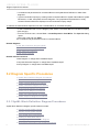
1.1 System Engineer Perspective
The SysML plugin is available in MagicDraw Standard and higher editions for an
additional fee.
In keeping with SysML unifying purpose, the System Engineer perspective was created to unify the diverse
modeling languages currently used by system engineers. All the features dedicated to SysML are accessible. You
can switch among perspectives at any time.
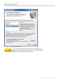
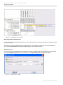
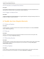
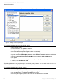
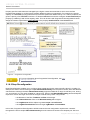
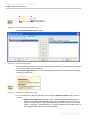
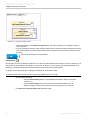
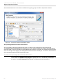
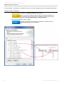
To switch to the System Engineer perspective
1. On the main menu, click Options > Perspectives > Perspectives.
2. In the Select Perspectives dialog, select System Engineer.
3. Click the Apply button.
7
Copyright © 2009-2015 No Magic, Inc.
GETTING STARTED
System Engineer Perspective
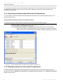
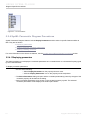
Figure 1 -- Select Perspectives dialog
For more information about how to work with perspectives, see
Perspectives Selection and Customization in the Getting Started
section in the MagicDraw User Manual.pdf.
8
Copyright © 2009-2015 No Magic, Inc.
1
S Y SM L D IAGRA MS
2.1 SysML Diagrams
All diagrams are described in the following sections:
SysML Block Definition Diagram (BDD)
SysML Internal Block Diagram (IBD)
SysML Package Diagram
SysML Parametric Diagram
Requirements Diagram
SysML Activity Diagram
SysML Use Case Diagram
Views and Viewpoints Diagram
SysML Sequence Diagram
SysML State Machine Diagram
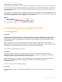
2.1.1 SysML Block Definition Diagram (BDD)
Description
A Block Definition Diagram defines the features of a block and any relationships between blocks such as
associations, generalizations, and dependencies, in terms of properties, operations, and relationships (for
example, a system hierarchy or a system classification tree).
Block Definition Diagrams are based on UML class diagrams and include restrictions and extensions as defined by
SysML. They are generally used to display systems of blocks or show a system dictionary and/or extensions.
9
Copyright © 2009-2015 No Magic, Inc.
SYSML DIAGRAMS
SysML Diagrams
Sample
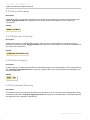
Figure 1 -- SysML Block definition diagram
Related elements
Block
Domain
External
System
Subsystem
System Context
Constraint Block
Interface Block
Flow Specification
Value Type
Quantity Kind
Unit
Related procedures
SysML Block Definition Diagram Procedures
Transferring mathematical expressions from MATLAB source code into the model
2.1.2 SysML Internal Block Diagram (IBD)
Description
Internal Block Diagrams are based on UML composite structure diagrams and include restrictions and extensions
as defined by SysML. An Internal Block Diagram captures the internal structure of a Block in terms of properties
and connections among properties. A Block includes properties so that its values, parts, and references to other
blocks can be specified. However, whereas an Internal Block Diagram created for a Block (as an inner element)
10
Copyright © 2009-2015 No Magic, Inc.
SYSML DIAGRAMS
SysML Diagrams
will only display the inner elements of a classifier (parts, ports, and connectors), an Internal Block Diagram created
for a package will display additional elements (shapes, notes, and comments).
All properties and connectors that appear inside an Internal Block Diagram belong to (are owned by) a Block
whose name is written in the diagram heading. That particular Block is the context of the diagram. SysML allows
any property (part) to be shown in an Internal Block Diagram to display compartments within the property (or part)
symbol.
Sample
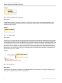
Figure 2 -- SysML Internal block diagram
Related elements
Part Property
Shared Property
Reference Property
Value Property
Constraint Property
Distributed Property
Flow Port
Full Port
Proxy Port
Directed Feature
Related procedures
SysML Internal Block Diagram Procedures
Transferring mathematical expressions from MATLAB source code into the model
11
Copyright © 2009-2015 No Magic, Inc.
SYSML DIAGRAMS
SysML Diagrams
2.1.3 SysML Package Diagram
Description
Package diagrams typically enable you to organize models by partitioning model elements into packageable
elements and establishing dependencies between packages and/or model elements within these packages. Since
Package diagrams are used to organize models in packages and views, they can include a wide array of
packageable elements.
A package is a construct that enables you to organize model elements, such as use cases or classes, into groups.
Packages define namespaces for packageable elements. Model elements from one package can be imported
and/or accessed by another package. This organizational principle is intended to help establish unique naming of
the model elements and avoid overloading a particular model element's name. Packages can also be shown on
Block Definition diagrams or Requirements diagrams.
Sample
NA
Related procedures
SysML Package Diagram Procedures
2.1.4 SysML Parametric Diagram
Description
Parametric diagrams can be defined as restricted forms of IBDs. They are similar to IBDs except that the only
connectors allowed are binding connectors, each having at least one end connected to a constraint parameter.
A Parametric diagram includes the usage of a constraint block to constrain the properties of another block. It
contains constraint properties and constraint parameters as well as other properties from within that internal block
context. All properties displayed, other than the constraints themselves, must either be bound directly to a
constraint parameter or contain a property that is bound to a constraint parameter (through any number of
containment levels). A constraint block generally contain many constraints, each of them containing many
constraint parameters.
Constrained properties typically have simple value types that can also carry units, quantity kinds, and probability
distributions. This allows for a value property that may be deeply nested within a containing hierarchy to be
referenced at the outer containing level. The context for the usages of constraint blocks must also be specified in
a parametric diagram to maintain the proper namespaces for the nested properties.
The state of the system can be specified in terms of the values of some of its properties. A change in state will
result in a different set of constraint equations to be recalculated. This can be accommodated by specifying
constraints that are conditioned on the value of the property with state.Parametric diagrams can be used to
support trade-off analysis. A constraint block can define an objective function to compare alternative solutions.
12
Copyright © 2009-2015 No Magic, Inc.
SYSML DIAGRAMS
SysML Diagrams
Sample
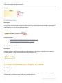
Figure 3 -- SysML Parametric diagram
Related elements
Moe
Objective Function
Binding Connector
Related procedures
SysML Parametric Diagram Procedures
Transferring mathematical expressions from MATLAB source code into the model
2.1.5 Requirements Diagram
Description
Requirements Diagrams provide modeling constructs to represent text-based requirements and relate them to
other modeling elements. These requirement modeling constructs are intended to provide a bridge between
traditional requirement management tools and other SysML models.
Requirements diagrams display requirements, packages, other classifiers, test cases, rationales, and
relationships. Possible relationships available for Requirements diagrams are containments, deriveReqt and
requirement dependencies (‘Copy’, ‘Refine’, ‘Satisfy’, ‘Trace’, and ‘Verify’). The callout notation can also be used
to reflect the relationships of other models.
13
Copyright © 2009-2015 No Magic, Inc.
SYSML DIAGRAMS
SysML Diagrams
Requirements can also be shown on other diagrams to illustrate their relationships to other modeling elements.
Sample
Figure 4 -- Requirements diagram
Related elements
Requirement
Extended Requirement
Functional Requirement
Interface Requirement
Performance Requirement
Physical Requirement
Design Constraint
Business Requirement
Usability Requirement
Test Case
Satisfy
Verify
Derive
Copy
Related procedures
Requirements Diagram Procedures
14
Copyright © 2009-2015 No Magic, Inc.
SYSML DIAGRAMS
SysML Diagrams
2.1.6 SysML Activity Diagram
Description
Activity diagrams describe control, input, and output flows among actions. They represent the system business
and operational work flows. They capture actions and display their results. They are typically used for business
process modeling and used in situations where all or most of the events represent the completion of internallygenerated actions.
Though Activity diagrams are often classified alongside interaction diagrams, they actually focus on the flows
driven by internal processes (as opposed to external events).
SysML extends control in Activity diagrams and provides extensions that might be very loosely grouped under the
term “continuous”, but are generally applicable to any distributed flow of information and physical items through a
system. It also introduces probability concepts to activities.
Sample
Figure 5 -- SysML Activity diagram
Related elements
Accept Change Structural Feature Event Action
Change Structural Feature Event
Invocation on Nested Port Action
Trigger on Nested Port
Related procedures
SysML Activity Diagram Procedures
Transferring mathematical expressions from MATLAB source code into the model
15
Copyright © 2009-2015 No Magic, Inc.
SYSML DIAGRAMS
SysML Diagrams
2.1.7 SysML Use Case Diagram
Description
The purpose of a Use Case Diagram is to give a graphical overview of the functionalities provided by a system in
terms of actors, their goals (represented as use cases), and any dependencies among those use cases.
A Use Case Diagram describes the usage of a system. The associations between actors and use cases represent
the communications that occur between the actors and the subjects to accomplish the functionalities associated
with the use cases. The subject of a use case can be represented through a system boundary. The use cases
enclosed in the system boundary represent the functionalities performed by behaviors (activity diagrams,
sequence diagrams, and state machine diagrams).
Actors may interact either directly or indirectly with the system. They are often specialized so as to represent a
taxonomy of user types or external systems. The only relationship allowed between actors in a use case diagram
is generalization. This is useful in defining overlapping roles between actors. Actors are connected to use cases
through communication paths, each represented by a relationship. There are four use case relationships:
• communication
• include
• extend
• generalization
Communication
A communication path represents an association between two Deployment Targets. It connects
actors to use cases.
Include
An include relationship provides a mechanism for factoring out a common functionality that is
shared among multiple use cases and is always performed as part of the base use case.
Extend
An extend relationship provides an optional functionality, which extends the base use case at
defined extension points under specified conditions.
Generalization
A generalization relationship provides a mechanism to specify variants of the base use case.
16
Copyright © 2009-2015 No Magic, Inc.
SYSML DIAGRAMS
SysML Diagrams
Use cases are often organized into packages with the corresponding dependencies among the use cases
included in the packages.
Figure 6 -- SysML Use Case diagram
Related elements
External System
Sensor
Boundary System
User System
Actuator
Environmental Effect
Related procedures
SysML Use Case Diagram Procedures
2.1.8 Views and Viewpoints Diagram
Description
The concept of View and Viewpoint reflects perspectives of different stakeholders. The views are constructed from
a subset of the model that addresses their concerns.
The new technology interprets Views and Viewpoints models to construct XML document conforming with
DocBook standard. A combination of diagrams, tables, model queries and simple text fragments can be presented
in a built-in preview window or exported to PDF or HTML documents.
17
Copyright © 2009-2015 No Magic, Inc.
SYSML DIAGRAMS
SysML Diagrams
Sample
Related elements
View
Viewpoint
Conform
2.1.9 SysML Sequence Diagram
This diagram is similar to UML Sequence Diagram.
2.1.10 SysML State Machine Diagram
This diagram is similar to UML State Machine Diagram.
18
Copyright © 2009-2015 No Magic, Inc.
1
S UPPO R TIVE DIA GRA MS
The supportive diagrams are:
• Requirements Table
• Dependency Matrix
• Predefined Relation Maps
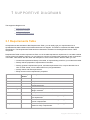
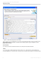
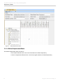
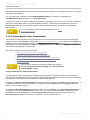
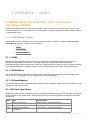
3.1 Requirements Table
All requirements are text-based. With Requirements Table, you can easily type your requirements into a
spreadsheet-like table instead of the limited-size boxes in a diagram. This table is consistent with OMG SysML
specifications. The Requirements Table has been refactored to be based on the MagicDraw Generic Table
component.
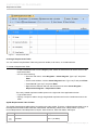
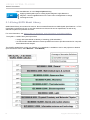
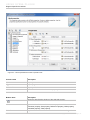
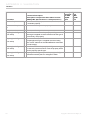
Requirements Table contains requirements. Each row in the table represents a requirement. A new table consists
of three columns by default. However, you can add more columns to represent the properties of each requirement
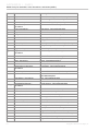
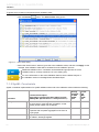
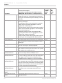
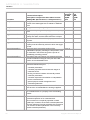
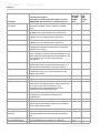
in the table. Table •below lists the name and description of some of the columns. With this table, you can:
• Create new requirements directly in the table, or import existing ones from your model to the table.
• Directly edit the properties of requirements in the table.
• Directly generate requirements reports, renumber requirements’ IDs, or export the table into a
CSV or HTML format, or into a Microsoft Excel (.xlsx) spreadsheet.
• Quickly search and filter requirements.
• Easily access custom requirement’s properties.
Column Name
Visible by
Default
Description
#
Y
A row number.
ID
Y
A requirement’s ID.
Name
Y
A requirement’s name.
Text
Y
A requirement text.
Requirement Type
N
A requirement’s type, for example, business requirement or
design constraint.
Owner
N
A Requirement’s owner.
Source
N
(For extendedRequirement and its subtypes only) The source
of a requirement.
Risk
N
(For extendedRequirement and its subtypes only) The risk
level of a requirement.
Verify Method
N
(For extendedRequirement and its subtypes only) The
method to verify a requirement.
19
Copyright © 2009-2015 No Magic, Inc.
SU PPORTIVE DIAGRAMS
Requirements Table
Figure 1 -- Requirements table
Creating A Requirements Table
You can create a Requirements Table using the main toolbar, main menu, or Containment tree.
To create a Requirements Table
1. In the Containment tree or on the diagram pane, select an element that can be the owner of the
requirement table.
2. Do one of the following:
• From the main menu, select Diagrams > Create Diagram. Type “reqT” and press
Enter.
• On the main toolbars, click the Create Diagram button. Type “reqT” and press Enter.
• Press Ctrl+N. Type “reqT” and press Enter.
• Right-click the element and from the shortcut menu select Create Diagram >
Requirement Diagrams > Requirement Table.
The newly created requirement table opens on the right side of the application window.
3. Type a table name.
4. Specify a scope for table or simply drag desired requirements from the Containment tree to the
table.
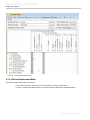
SysML Requirements Table Toolbar
The SysML Requirements table toolbar is located on the main toolbar. There are 13 Requirements table icons on
the Requirements table toolbar: Add New, Add Nested, Add Existing, Delete From Table, Delete, Up, Down,
Unnest Requirement, Nest Requirement, Report, Show Columns, Show Full Paths, and Export.
Icon
Name
Keyboard Shortcut
Insert
Add New
20
Ctrl + I (on MAC)
Copyright © 2009-2015 No Magic, Inc.
SU PPORTIVE DIAGRAMS
Requirements Table
Icon
Name
Keyboard Shortcut
Alt + Insert
Add Nested
Alt + I (on MAC)
Ctrl + Insert
Add Existing
Ctrl + E (on MAC)
Delete From Table
Delete
Delete
Ctrl + D
Up
Ctrl + Up
Down
Ctrl + Down
Unnest Requirement
n/a
Nest Requirement
n/a
Report
n/a
Show Columns
n/a
Show Full Paths
n/a
Export
n/a
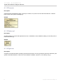
Add New
You can either click the Add New icon on the table toolbar or press Insert to add a new requirement which will
then be automatically added to the table.
If you click the icon, the available requirement types will be listed in the drop-down menu. If you have created your
own custom requirement types, they will appear under the Custom Requirements group in the menu, for
example, “myRequirement” in the following figure. Then, select a requirement type that you want to create from
the drop-down menu. A requirement of the selected type will then be created and added to the table.
21
Copyright © 2009-2015 No Magic, Inc.
SU PPORTIVE DIAGRAMS
Requirements Table
• The owner of the newly-created requirement will be similar to the
owner of the table.
• To select a different owner, hold Shift and then select a
requirement type from the drop-down menu. The Select Owner
dialog will then open, enabling you to choose a different owner.
• If a table row is selected, the requirement in that row will be
selected in the Select Owner dialog automatically.
If the selected owner is a requirement, then you are creating a new
nested requirement.
If you click the buttons, a requirement will be created promptly. You can then change the type of the newly-created
requirement directly in the table.
Add Nested
When a requirement is highlighted in the table, you can either click the Add Nested icon on the table toolbar or
press Alt + Insert to add a new nested requirement, owned by the highlighted requirement, to the table.
Like Add New, if you click the icon, the available requirement types will be listed in the drop-down menu. Then,
select a requirement type that you want to create from the drop-down menu. A nested requirement of the selected
type will then be created, being owned by the requirement highlighted in the table.
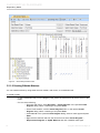
Add Existing
To add requirement(s) already existed in your model to a SysML Requirements Table
1. Click the Add Existing icon on the table toolbar or press Ctrl + Insert. The Select Requirement
dialog will open.
22
Copyright © 2009-2015 No Magic, Inc.
SU PPORTIVE DIAGRAMS
Requirements Table
Figure 2 -- Select Requirement Dialog - Add existing requirements to table
2. Select the requirement element(s) which you want to add to the table.
• Use the Add button to add a requirement selected in the element tree to the Selected
elements: pane.
• Use the Add Recursively button to add all requirements listed under the requirement
selected in the element tree and the selected requirement itself to the Selected
elements: pane.
• Use the Remove button to remove the selected requirement from the Selected
elements: pane.
• Use the Remove All button to remove all requirements from the Selected elements:
pane.
3. In the Select Requirement dialog, click
• OK to add all requirements in the Selected elements: pane to the table, or
• Cancel to cancel the operation.
Delete From Table
To remove requirement(s) from a SysML Requirements Table
1. Select the row(s) of the requirement(s) you want to remove.
23
Copyright © 2009-2015 No Magic, Inc.
SU PPORTIVE DIAGRAMS
Requirements Table
2. Click the Delete From Table icon on the table toolbar or press Delete.
3. The selected requirement(s) will then be removed from the table.
Delete
To remove a requirement(s) from your model
1. Select the row(s) of requirement(s) you want to remove.
2. Click the Delete icon on the table toolbar or press Ctrl + D.
3. The selected requirement(s) will then be removed from the table and from your project.
Up
To move the selected row of requirement up, either click the Up icon on the table toolbar or press Ctrl + Up.
Down
To move the selected row of requirement down, either click the Down icon on the table toolbar or press Ctrl +
Down.
Unnest Requirement
When a nested requirement is selected in the Requirements Table, you can click the Unnest Requirement to
move the selected requirement to be owned by the owner of the current one. The requirement's id will be changed
accordingly. Unnest Requirement also supports for the multiple selection of the nested requirements which are
owned by the same owner.
Nest Requirement
You can select a requirement in the Requirements Table and then click on the Nest Requirement to move the
selected requirement to be owned by the requirement in the previous row. Nest Requirement also support for the
multiple selection of the requirements.
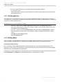
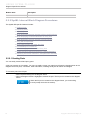
Report
The SysML Requirements Table allows you to generate a requirements report directly from the table. The default
report template used is Requirements Table (Type A).
To generate a report, click the Report icon on the table toolbar. The template drop-down menu will then open.
Select the report template you would like to use. The Generate Report dialog will then open. Choose the report
output filename and then click Generate to instantly generate the report.
• All requirements in the table will be used as the scope of the
generated report.
• To change the scope of the report, activate Report Wizard by
clicking the Wizard button in the Generate Report dialog. Click
the Next button in the Report Wizard twice to proceed to the
Select Element Scope pane. You can then change the report
scope using this pane.
The Built-in report data (in the Select Report Data pane of
Report Wizard) must be selected, in order to generate a report
from this table.
See Section Appendix III. Open API for more information on report generation.
24
Copyright © 2009-2015 No Magic, Inc.
SU PPORTIVE DIAGRAMS
Requirements Table
Figure 3 -- Generate Report dialog - SysML Requirements Table
Show Columns
To show or hide columns in the table, click the Show Columns icon on the table toolbar. The Table Column
drop-down menu will then display.
Select a column name to display that column on the table (or deselect a column name to hide it). To customize
displayed columns, select Customize Column. The Select Custom Requirement Columns dialog will then
display.
25
Copyright © 2009-2015 No Magic, Inc.
SU PPORTIVE DIAGRAMS
Requirements Table
Figure 4 -- Select Custom Requirement Columns dialog
Select a property / tag to be displayed as a new column of the Requirements Table, and then click OK. The new
column will then display on the table. To be able to select multiple properties / tags to be displayed, use the
Multiple Selection button.
Show Full Paths
If you select an element in the table and click this icon, the full path of the element will show.
Export
You can also export a SysML Requirements Table to HTML, CSV, or Microsoft Excel (.xlsx) spreadsheet by
clicking the Export icon on the table toolbar. All requirements in the table will be exported to a selected file format.
26
Copyright © 2009-2015 No Magic, Inc.
SU PPORTIVE DIAGRAMS
Dependency Matrix
3.2 Dependency Matrix
Dependency Matrix enables you to visualize and represent your particular model in a tabular form, depending on
the scopes and dependency criteria you have selected.
• Scope. There are two types of scope: row scope and column scope. You can select diagrams,
UML elements, and/or SysML elements as a scope.
• Dependency criteria: include UML relationships, SysML relationships, semantic dependencies
(dependency through property), and relationships through tags.
Cells in a dependency matrix show where the elements in the selected scope are associated with or related to one
another. A dependency matrix allows you to visualize the many-to-many traceability of elements from different
diagrams, particularly for elements interconnected in a large system.
A dependency matrix helps you:
• Quickly visualize dependency criteria.
• Compactly visualize the relationships of a large system, which cannot be easily represented by a
diagram on a single sheet of paper because of the diagram complexity.
• Visualize domain-specific relationships through your own matrix templates for such domains.
• Understand relationships from a particular scope by filtering the unimportant kinds of model
elements.
• Display relationships that cannot be represented in diagrams, such as representations (classes by
lifeline), behavior representations in other diagrams, operation representations by Call Behavior
Actions, etc.
For more information on the Dependency Matrix feature, see the Model Analysis in the ‘Dependency Matrix’
section in the MagicDraw User Manual.
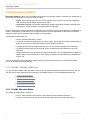
3.2.1 SysML Editable Matrices
You can edit three SysML matrix templates. Not only can you display dependencies between elements, but you
can also add or delete dependency(ies) directly in the editable matrices. The three editable matrices are:
• SysML Allocation Matrix
• Satisfy Requirement Matrix
• Verify Requirement Matrix.
• Refine Requirement Matrix
• Derive Requirement Matrix
3.2.1.1 SysML Allocation Matrix
The SysML Allocation Matrix consists of:
• Row: a named element that can be the client element of the Allocate dependency.
• Column: a named element that can be the supplier element of the Allocate dependency.
27
Copyright © 2009-2015 No Magic, Inc.
SU PPORTIVE DIAGRAMS
Dependency Matrix
Figure 5 -- SysML Allocation matrix
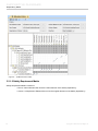
3.2.1.2 Satisfy Requirement Matrix
Satisfy Requirement Matrix consists of:
• Row: a named element that can be the client element of the Satisfy dependency.
• Column: a Requirement Element that can be the supplier element of the Satisfy dependency.
28
Copyright © 2009-2015 No Magic, Inc.
SU PPORTIVE DIAGRAMS
Dependency Matrix
Figure 6 -- Satisfy Requirement matrix
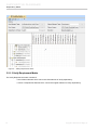
3.2.1.3 Verify Requirement Matrix
The Verify Requirement matrix consists of:
• Row: Named element which can be the client element of Verify dependency.
• Column: Requirement Element which can be the supplier element of Verify dependency.
29
Copyright © 2009-2015 No Magic, Inc.
SU PPORTIVE DIAGRAMS
Dependency Matrix
Figure 7 -- Verify Requirement matrix
3.2.1.4 Refine Requirement Matrix
The Refine Requirement matrix consists of:
• Row: Named element which can be the client element of Refine dependency.
• Column: Requirement Element which can be the supplier element of Refine dependency.
30
Copyright © 2009-2015 No Magic, Inc.
SU PPORTIVE DIAGRAMS
Dependency Matrix
Figure 8 -- Refine Requirements matrix
3.2.1.5 Derive Requirement Matrix
The Derive Requirement matrix consists of:
• Row: Named element which can be the client element of Derive dependency.
• Column: Requirement Element which can be the supplier element of Derive dependency.
31
Copyright © 2009-2015 No Magic, Inc.
SU PPORTIVE DIAGRAMS
Dependency Matrix
Figure 9 -- Derive Requirement matrix
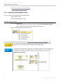
3.2.1.6 Creating Editable Matrices
You can create matrices by using either the main toolbar, main menu, or Containment tree.
To create a matrix
1. In the Containment tree or on the diagram pane, select an element that can be the owner of the
matrix.
2. Do one of the following:
• From the main menu, select Diagrams > Create Diagram. In the opened Create
Diagram dialog, select a matrix type and press Enter.
• On the main toolbars, click the Create Diagram button. In the opened Create
Diagram dialog, select a matrix type and press Enter.
• Press Ctrl+N. In the opened Create Diagram dialog, select a matrix type and press
Enter.
• Right-click the element and from the shortcut menu select Create Diagram >
Requirement Diagrams or SysML Matrices and click a desired matrix type.
32
Copyright © 2009-2015 No Magic, Inc.
SU PPORTIVE DIAGRAMS
Dependency Matrix
The newly created matrix opens on the right side of the application window.
3. Type a matrix name.
4. Select criteria and a scope to be represented in the matrix or simply drag desired elements from
the Containment tree.
3.2.1.7 Building Matrices
The matrices you have created in Section 3.2.1.6 (Creating Editable Matrices) are empty matrices. To build a
complete matrix, you must also provide the row and column scopes of the matrix. All valid elements in the selected
scope will be used to build the matrix.
To select the row and column scopes of a matrix:
1. Click the ... button next to the Row Scope in the matrix pane. The Scope dialog opens.
2. Select the check box(es) in front of the packages, models, or profiles that will be the row scope.
3. Click OK to close the Scope dialog.
4. Click the ... button next to the Column Scope in the matrix pane. The Scope dialog will open.
5. Select the check box(es) in front of the packages, models, or profiles that will be the column
scope.
6. Click OK to close the Scope dialog.
7. Click the Refresh button.
3.2.1.8 Editing Matrix
You can create or remove dependencies directly in an editable matrix. Double-click an empty rectangle in the
matrix to create a new dependency, or double-click an existing dependency in the matrix to remove it.
Creating New Dependencies
You can create a corresponding dependency of each matrix directly in the matrix by double-clicking on the
intersection of the row and column elements. The row and column elements will become the client and supplier
elements of the created dependency respectively.
Another way to create a dependency is by right-clicking on the intersection of the row and column elements. Then,
select New Relation > Outgoing, and select the dependency you would like to create.
33
Copyright © 2009-2015 No Magic, Inc.
SU PPORTIVE DIAGRAMS
Dependency Matrix
Figure 10 -- Editable Matrix context menu
Removing Existing Dependencies
You can also remove an existing dependency of each matrix by double-clicking on that particular dependency that
you want to remove.
Another way to remove a dependency is by right-clicking on the intersection of the row and column elements.
Then, select Delete Relation, and select the dependency you would like to delete.
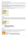
Dependency List
You can view a list of dependencies associated with a cell in an editable matrix by right-clicking on the cell, and
then select Dependency List from the context menu. The Dependency List dialog will then display.
Figure 11 -- Dependency List dialog
34
Copyright © 2009-2015 No Magic, Inc.
SU PPORTIVE DIAGRAMS
Predefined Relation Maps
3.3 Predefined Relation Maps
The SysML plugin introduces a predefined set of Relation maps to increase traceability of system requirements
and design elements.
There are three predefined relation maps:
• Structure Decomposition Map
• Activity Decomposition Map
• Instance Map
The Relation map is a special kind of diagram that automatically updates and renders an elements dependency
tree according to predefined dependency criteria.
For more information about selecting and creating elements, see
section “Manipulations in Relation Map” in “MagicDraw
UserManual.pdf”.
35
Copyright © 2009-2015 No Magic, Inc.
1
S Y SM L ELEME NTS
4.1 SysML Block Definition Diagram Elements
4.1.1 Block
Description
Blocks provide a general purpose capability to describe the architecture of a system, and represent the system
hierarchy in terms of systems and subsystems. Blocks describe not only the connectivity relationships within /
between a system and its subsystems, but also quantitative values as well as other information about that system
(for example, documentation).
You can use SysML blocks throughout all phases of system specification and design, and apply them to many
different kinds of systems. These include modeling either the logical or physical decomposition of a system, and
the specification of software, hardware, or human elements.
A Block is a modular unit that describes the structure of a system or an element. It may include both structural and
behavioral features, such as properties and operations, that represent the state of the system and behavior that
the system may exhibit. Some of these properties may hold parts of a system, which can also be described by
blocks. A block may include a structure of connectors between its properties to indicate how its parts or other
properties relate to one another.
Any reusable form of description that may be applied to a system or a set of system characteristics can be
described by a block. Such reusable descriptions, for example, may be applied to purely conceptual aspects of a
system design, such as relationships that hold between parts or properties of a system. Parts (properties) in these
systems can interact by many different means, such as software operations, discrete state transitions, flows of
inputs and outputs, or continuous interactions. Connectors owned by SysML blocks can be used to define
relationships between parts or other properties of the same containing block.
Sample
Related procedures
NEW! Displaying Direction Prefixes of Proxy and Full Ports
NEW! Managing Interfaces of the Block
NEW! Managing Block properties
36
Copyright © 2009-2015 No Magic, Inc.
SYSML ELEMENTS
SysML Block Definition Diagram Elements
4.1.2 Domain
Description
A Domain block represents an entity, a concept, a location, or a person from the real-world domain. A domain
block is part of the system knowledge [1].
Sample
4.1.3 External
Description
An External block is a block that represents an actor. It facilitates a more detailed modeling of actors like ports or
internal structures [1].
Sample
4.1.4 System
Description
A System is an artificial artifact consisting of blocks that pursue a common goal which cannot be achieved by the
system's individual elements. A block can be a software, hardware, a person, or an arbitrary unit [1].
37
Copyright © 2009-2015 No Magic, Inc.
SYSML ELEMENTS
SysML Block Definition Diagram Elements
Sample
4.1.5 Subsystem
Description
A Subsystem is a typically large, encapsulated block within a larger system [1].
Sample
4.1.6 System Context
Description
A System context element is a virtual container that includes the entire system and its actors [1].
Sample
4.1.7 Constraint Block
Description
Constraint blocks provide a mechanism for integrating engineering analysis such as performance and reliability
models with other SysML models. Constraint blocks can be used to specify a network of constraints that represent
mathematical expressions such as {F=m*a} and {a=dv/dt}, which constrain the physical properties of a system.
Such constraints can also be used to identify critical performance parameters and their relationships to other
parameters, which can be tracked throughout the system life cycle. A constraint block includes constraints (such
38
Copyright © 2009-2015 No Magic, Inc.
SYSML ELEMENTS
SysML Block Definition Diagram Elements
as {F=m*a}) and their parameters (such as F, m, and a). Constraint blocks define generic forms of constraints that
can be used in multiple contexts.
Reusable constraint definitions can be specified on Block Definition Diagrams and packaged into general-purpose
or domain-specific model libraries. Such constraints can be arbitrarily complex mathematical or logical
expressions. The constraints can be nested to enable a constraint to be defined in terms of more basic constraints
such as primitive mathematical operators.
In general, you should define constraints in constraint blocks in a Block Definition Diagram first, and then use a
Parametric Diagram to bind constraint parameters to properties.
Sample
4.1.8 Interface Block
Description
An Interface Block is a special kind of block for typing proxy ports. It has no behaviors or internal parts. Normally,
it contains a set of flow properties which can be shown in the “flow properties” compartment. An interface block is
introduced in OMG SysML 1.3 specification to replace the use of flow specifications which have been deprecated.
Sample
Related procedures
NEW! Managing Interfaces of the Block
NEW! Managing Interfaces of the Proxy Port
4.1.9 Flow Specification
Description
A Flow Specification specifies inputs and outputs as a set of flow properties. It has a “flowProperties” compartment
that lists the flow properties. A flow specification is used to type Flow Ports, in order to specify items which can
flow via the ports.
The only valid attribute of a Flow Specification element is a Flow
Property.
For more information on the flow port and the flow properties,
please refer to the "SysML Internal Block Diagram Procedures"
chapter.
39
Copyright © 2009-2015 No Magic, Inc.
SYSML ELEMENTS
SysML Block Definition Diagram Elements
Sample
4.1.10 Value Type
Description
A Value Type is defined as a stereotype of UML Data Type to establish a more neutral term for system values that
may never be given a concrete data representation. A Value Type adds an ability to carry a unit of measure of a
quantity kind associated with the value. If these additional characteristics are not required, then UML Data Type
may be used (it is, however, not recommended by SysML 1.3 specification).
In general, define quantity kinds first, followed by units and their quantity kinds. After that, define value types and
their units (and quantity kinds). However, users often forget to enter the corresponding quantity kind of a value
type with unit. An existing active validation constraint for filling the correct quantity kind to a value type with
unspecified quantity kind, by selecting the Apply valid quantity kind to the Value Type option. For more
information, see the "Validation" chapter.
You can select value types from the model library that holds more than 80 units
and quantity kinds of SI system.
Sample
4.1.11 Quantity Kind
Description
A Quantity Kind (in SysML 1.0 and 1.1, called ‘Dimension’) is a kind of quantity that can be measured using
defined and unrestricted units of measurement. For example, length, a quantity kind, may be measured by meter,
kilometer, or foot units.
The only valid use of a Quantity Kind instance is to be referenced by the “quantity
kind” property of a Value Type or Unit stereotype.
40
Copyright © 2009-2015 No Magic, Inc.
SYSML ELEMENTS
SysML Internal Block Diagram Elements
Sample
4.1.12 Unit
Description
A Unit is a particular value that can be used to specify a quantity of a dimension. A unit often relies on precise and
reproducible measuring techniques. For example, a unit of length such as meter may be specified as a multiple of
a particular wavelength of light. A unit can also use less stable or precise ways to express some values, such as
costs expressed in some currencies, or a severity rating measured by a numerical scale.
The only valid use of a Unit instance is to be referenced by the “unit” property of a
Value Type stereotype.
Sample
4.2 SysML Internal Block Diagram Elements
4.2.1 Part Property
Description
A Part Property is a property that specifies a part with strong ownership and coincidental lifetime of its containing
Block. It describes a local usage or a role of the typing Block in the context of the containing Block. Every Part
Property has ‘composite’ AggregationKind and is typed by a Block. Part Properties are displayed in the ‘parts’
compartment.
Sample
Related Procedures
NEW! Displaying Direction Prefixes of Flow Property
41
Copyright © 2009-2015 No Magic, Inc.
SYSML ELEMENTS
SysML Internal Block Diagram Elements
4.2.2 Shared Property
Description
A Shared Property is a property that specifies a shared part of its containing block. Every Shared Property has
‘shared’ Aggregationkind and is typed by a block. Shared Properties are displayed in the ‘references’
compartment.
Sample
4.2.3 Reference Property
Description
A Reference Property is a property that specifies a reference of its containing Block to another Block. Every
Reference Property has ‘none’ AggregationKind and is typed by a block. Reference Properties are displayed in
the ‘references’ compartment.
Sample
4.2.4 Value Property
Description
A Value Property is a property that specifies the quantitative property of its containing Block. Every Value Property
has ‘composite’ AggregationKind and is typed by a SysML Value Type. Value Properties are displayed in the
‘values’ compartment.
Sample
4.2.5 Constraint Property
Description
A Constraint Property is a property that specifies the constraints of other properties in its containing Block. Every
Constraint Property has ‘composite’ AggregationKind and is typed by a Constraint Block. Constraint Properties
are displayed in the ‘constraints’ compartment.
42
Copyright © 2009-2015 No Magic, Inc.
SYSML ELEMENTS
SysML Internal Block Diagram Elements
Sample
4.2.6 Distributed Property
Description
A Distributed Property is a property of a Block or a Value Type, used to apply a probability distribution to the
values of the property. Specific distributions can be defined by applying a subclass of the DistributedProperty
stereotype to the property.
Sample
4.2.7 Flow Port
Description
A Flow Port is a port that specifies the input and output items that can flow between a Block and its environment.
Flow Ports are interactions points through which data, material, or energy “can” enter or leave the owning Block.
The specification of what can flow is achieved by typing the Flow Port with a specification of things that flow. This
can include typing an atomic Flow Port with a single type (Block, Value Type, or Signal) representing the items
that flow in or out, or typing a non-atomic Flow Port with a Flow Specification which lists multiple items that can
flow. In general, Flow Ports are intended to be used for asynchronous, broadcast, or send-and-forget interactions.
Note that only non-atomic Flow Ports can be conjugated. Once conjugated, all the directions of the typing Flow
Specification's items are negated.
Sample
4.2.8 Full Port
Description
A Full Port is a port which is considered as a separated element of owning blocks. It may have internal parts or
behaviors that support interactions with owning blocks.
43
Copyright © 2009-2015 No Magic, Inc.
SYSML ELEMENTS
Views and Viewpoints Diagram Elements
Sample
4.2.9 Proxy Port
Description
A Proxy Port is a port that specifies features of owning blocks or internal parts that are available to external blocks
through external connectors to the ports. It does not specify separated elements of the owning blocks or the
internal parts. It can only be typed by Interface Block.
Sample
Related procedures
NEW! Displaying Direction Prefixes of Proxy and Full Ports
NEW! Displaying Combined Direction on Proxy Port
NEW! Managing Interfaces of the Proxy Port
4.2.10 Directed Feature
Description
A directed feature is a feature which applies the «DirectedFeature» stereotype. It specifies that the feature is
provided, required, or both required and provided by an owning block.
Sample
4.3 Views and Viewpoints Diagram Elements
4.3.1 View
Description
A view is a representation of a whole system from the perspective of a single viewpoint. A view can only own
element import, package import, comment, and constraint elements.
44
Copyright © 2009-2015 No Magic, Inc.
SYSML ELEMENTS
Views and Viewpoints Diagram Elements
Sample
4.3.2 Viewpoint
Description
A viewpoint is a specification of the conventions and rules for constructing and using a view for the purpose of
addressing a set of stakeholder concerns. The languages and methods for specifying a view can reference
methods and languages in another viewpoint. They specify the elements expected to be represented in the view
that may be formally or informally defined.
A viewpoint cannot own any operation nor attribute.
Sample
4.3.3 Conform
Description
A Conform relationship is a dependency between a view and a viewpoint. The view conforms to the rules and
conventions specified in the viewpoint.
45
Copyright © 2009-2015 No Magic, Inc.
SYSML ELEMENTS
SysML Parametric Diagram Elements
Sample
4.4 SysML Parametric Diagram Elements
4.4.1 Moe
Description
moe (measure of effectiveness) represents a parameter whose value is critical for achieving the desired cost
effectiveness mission.
Sample
4.4.2 Objective Function
Description
An Objective Function (also known as 'optimization' or 'cost function') is used for determining the overall value of
an alternative in terms of weighted criteria and/or moe's.
Sample
4.4.3 Binding Connector
Description
A Binding Connector is a connector which specifies that the properties at both ends of the connector have equal
values. If the properties at both ends of a binding connector are typed by DataTypes or ValueTypes, it means that
the instances of the properties at both ends must hold equal values, recursively through any nested properties
within the connected properties. If the properties at both ends of a binding connector are typed by Blocks, it means
that the instances of the properties must refer to the same block instance. As with any connector owned by a
SysML Block, each end of a binding connector may be nested within a multi-level path of properties accessible
from the owning Block. The NestedConnectorEnd stereotype is used to represent such nested ends, just as for
nested ends of other SysML connectors.
46
Copyright © 2009-2015 No Magic, Inc.
SYSML ELEMENTS
SysML Requirements Diagram Elements
Constraint blocks can only be defined on a BDD or a package diagram. A constraint block typically contains one or
more constraint parameters, which are bound to properties of other blocks in a surrounding context where the
constraint is used.
All properties of a constraint block are constraint parameters, with the exception of constraint properties that hold
the internally-nested usages of other constraint blocks. Constraints are specified only in an informal language, but
a more formal language such as OCL or MathML could also be used.
Sample
4.5 SysML Requirements Diagram Elements
4.5.1 Requirement
Description
A Requirement specifies a capability or a condition that must (or should) be satisfied. Requirements are used to
establish a contract between the customer (or other stakeholders) and those responsible for designing and
implementing the system. A requirement can also appear on other diagrams to show its relationship to other
modeling elements.
When a requirement nests other requirements, all the nested requirements apply as part of the container
requirement (the requirement that contains all the nested requirements). Deleting the container requirement will
thus delete all the nested requirements it contains; a functionality inherited from UML.
4.5.2 Extended Requirement
Description
A SysML Extended Requirement is a standard Requirement subtype, which adds some properties to a
requirement element. These properties such as source, risk and verify method are important for requirement
management. Specific projects should add their own properties.
All these properties are now available in the standard Requirement Specification window and Requirements
Table. If any of these property values is specified, a requirement is automatically converted to
ExtendedRequirement.
4.5.3 Functional Requirement
Description
A Functional Requirement is a requirement that specifies a behavior that a system or part of a system must
perform.
47
Copyright © 2009-2015 No Magic, Inc.
SYSML ELEMENTS
SysML Requirements Diagram Elements
4.5.4 Interface Requirement
Description
An Interface Requirement is a requirement that specifies the ports for connecting systems and parts of a system.
Optionally, it may include the items that flow across the connector and/or the Interface constraints.
4.5.5 Performance Requirement
Description
A Performance Requirement refers to a requirement that quantitatively measures the extent to which a system or
a system part satisfy a required capability or condition.
4.5.6 Physical Requirement
Description
A Physical Requirement specifies the physical characteristics and/or physical constraints of a system, or a system
part.
4.5.7 Design Constraint
Description
A Design Constraint is a requirement that specifies a constraint on the implementation of a system or on part of it.
4.5.8 Business Requirement
Description
A Business Requirement is a requirement that specifies characteristics of the business process that must be
satisfied by the system.
4.5.9 Usability Requirement
Description
A Usability Requirement specifies the fitness for use of a system for its users and other actors.
4.5.10 Test Case
Description
A test case (Activity / StateMachine / Interaction) is a method for verifying a requirement.
48
Copyright © 2009-2015 No Magic, Inc.
SYSML ELEMENTS
SysML Activity Diagram Elements
4.5.11 Satisfy
Description
A 'Satisfy' relationship is a dependency between a requirement and a model element that fulfills that requirement.
As with other dependencies, the arrow direction points from the satisfying (client) model element to the (supplier)
requirement that is satisfied.
4.5.12 Verify
Description
A 'Verify' relationship is a dependency between a requirement and a test case or a model element that can
determine whether the system fulfills the requirement. As with other dependencies, the arrow direction points from
the (client) test case to the (supplier) requirement.
4.5.13 Derive
Description
A 'Derive' relationship is a dependency between two requirements (a derived requirement and a source
requirement), where the derived requirement is generated or inferred from the source requirement.
4.5.14 Copy
Description
A 'Copy' relationship is a dependency between a supplier requirement (master) and a client requirement (slave),
specifying that the client requirement text is a read-only copy of the supplier requirement text.
4.6 SysML Activity Diagram Elements
4.6.1 Accept Change Structural Feature Event Action
Description
An Accept Change Structural Feature Event Action is an action that waits for the occurrence of a Change
Structural Feature Event.
4.6.2 Change Structural Feature Event
Description
A Change Structural Feature Event is an event which is used to model changes in values of structural features.
49
Copyright © 2009-2015 No Magic, Inc.
SYSML ELEMENTS
SysML Use Case Diagram Elements
4.6.3 Invocation on Nested Port Action
Description
An Invocation on Nested Port Action is an invocation action that applies the «InvocationOnNestedPortAction»
stereotype which extends the UML’s onPort property to support nested ports.
4.6.4 Trigger on Nested Port
Description
A Trigger on Nested Port is a trigger that applies the «TriggerOnNestedPort» stereotype extending the UML’s Port
property of the trigger to support nested ports.
4.7 SysML Use Case Diagram Elements
4.7.1 External System
Description
An External System is a system that interacts with the system under development. For example, Information
server or Monitoring system [1].
4.7.2 Sensor
Description
A Sensor is a special external system that forwards information from the environment to the system under
development. For example, Temperature sensor [1].
4.7.3 Boundary System
Description
A Boundary System is a special external system that serves as medium between another system and the system
under development without having its own interests in the communication. For example, Bus system or
Communication system [1].
4.7.4 User System
Description
An User System is a special external system that serves as medium between a user and the system without
having its own interests in the communication. For example, Input Device or Display [1].
50
Copyright © 2009-2015 No Magic, Inc.
SYSML ELEMENTS
SysML Use Case Diagram Elements
4.7.5 Actuator
Description
An Actuator is a special external system that influences the environment of the system under development. For
example, Heater assembly or Central locking system of a car [1].
4.7.6 Environmental Effect
Description
An Environmental Effect is an influence on the system from the environment without communicating with it
directly. For example, Temperature or Humidity [1].
51
Copyright © 2009-2015 No Magic, Inc.
1
U S ING SYSML P LUGIN
You can find out the useful information about working with SysML plugin while studying:
• Generic Procedures
• Diagram Specific Procedures
5.1 Generic Procedures
Depending on whether you want to:
• Creating SysML Projects
• Creating SysML Projects From Templates
• Using OMG SysML Style
• Using QUDV Model Library
• Using Quick Search Dialog
• Using Structure Browser
• Generating SysML reports
• Context-Specific Value Compartments
• Feature-based Compartments
• NEW! Managing Element Groups
• NEW! Displaying Rake icon on symbol
• Transferring mathematical expressions from MATLAB source code into the model
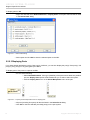
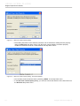
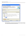
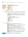
5.1.1 Creating SysML Projects
To create a new workspace for a new project
1. Do one of the following:
• Click File > New Project on the main menu.
• Click the New Project button on the main toolbar.
• Press CTRL+N.
The New Project dialog will open.
2. Click the SysML Project icon on the left-hand side.
3. Enter a filename in the Name box.
4. Click the “...” button to select a location for your new project.
5. Click OK.
If the current perspective is not the System Engineer perspective, the Open Associated Perspective dialog will
open. Select Yes to change it to the System Engineer perspective.
52
Copyright © 2009-2015 No Magic, Inc.
USING SYSML PLUGIN
Generic Procedures
Figure 1 -- New Project dialog
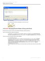
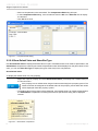
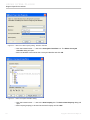
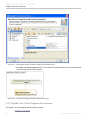
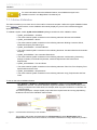
5.1.2 Creating SysML Projects From Templates
To create a SysML project from a template
1. Do one of the following:
• Click File > New Project on the main menu.
• Click the New Project button on the main toolbar.
• Press CTRL+ N.
The New Project dialog opens.
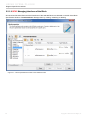
2. Click the Project from Template icon.
3. Enter a filename in the Name box.
4. Click the “...” button to select a location for your new project.
5. Select the SysML template from the Select template tree and click OK.
53
Copyright © 2009-2015 No Magic, Inc.
USING SYSML PLUGIN
Generic Procedures
Figure 2 -- Selecting SysML template
For more information on how to work with a new project, see the
Working with Projects section in the MagicDraw UserManual.pdf.
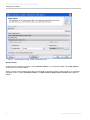
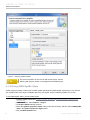
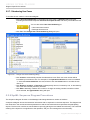
5.1.3 Using OMG SysML Style
SysML plugin provides the visual style of OMG SysML Specifications (OMG SysML style) that you can use with
your SysML model. Such style is available with every new SysML project created by SysML 16.8 or later.
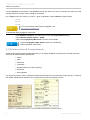
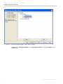
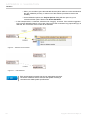
To use OMG SysML style in a new SysML project
1. Create a SysML project (see "Creating SysML Projects" or "Creating SysML Projects From
Templates").
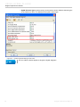
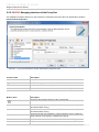
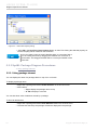
2. In the main menu, select Options > Project.
3. The Project Options dialog will open.
4. Select the Symbols properties styles node (on the left-hand side), and then select OMG SysML
style in the Symbols properties styles panel.
5. Click the Make Default button.
54
Copyright © 2009-2015 No Magic, Inc.
USING SYSML PLUGIN
Generic Procedures
6. Click OK. Your SysML project will use OMG SysML style as a default style.
Figure 3 -- Setting symbol properties style
To apply OMG SysML style to an existing SysML project
1. Open a SysML project.
2. On the main menu, click Options > Project.
3. The Project Options dialog will open.
4. Select the Symbols properties styles node (on the left-hand).
5. Select OMG SysML style, click Make Default > OK. (Skip steps 6 to 10.)
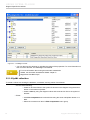
6. If you do not see the OMG SysML style option in the Symbols properties styles panel, click the
Import button. The Open dialog opens.
7. Open the <md.install.dir>/templates/SysML directory and select OMG SysML style.stl.
8. Click Open.
9. The OMG SysML style option will appear in the Symbols properties styles panel.
10. Select it, click Make Default > OK.
The OMG SysML style is now a default style in your SysML project. However, you can apply such style only to a
SysML diagram. The following steps show you how to apply the style to a SysML diagram.
To apply OMG SysML style on a SysML diagram
1. Open the Project Options dialog.
2. Select OMG SysML style in the Symbols properties styles panel.
3. Click the Apply button. The Select Diagrams dialog opens.
4. Select a SysML diagram (you can select more than one diagram) and click OK.
55
Copyright © 2009-2015 No Magic, Inc.
USING SYSML PLUGIN
Generic Procedures
5. Click the OK button in In the Project Options dialog.
Applying OMG SysML style to existing SysML diagrams might distort the
diagrams. Use the Layout feature on the main menu of MagicDraw to change
how diagram looks.
5.1.4 Using QUDV Model Library
QUDV Model Library is introduced in Annex C: Non-normative Extensions to OMG SysML Specifications 1.3. This
model library is designed in such a way that extensions to ISQ and SI can be represented, as well as any
alternative systems of quantities and units.
For more information, see "Model Library for Quantities, Units, Dimensions, and Values (QUDV)".
The SysML 1.4 QUDV library was improved to
• comply with International vocabulary of metrology (VIM 3rd edition)
• encode ISO/IEC 80000 definitions of base quantities and units to provide semantics for computer-
based dimensional analysis.
The ISO/IEC 80000 library, which is a collection of 14 standards, is available to use in new projects on demand
(from the shortcut menu, select Modules > Load Module).
56
Copyright © 2009-2015 No Magic, Inc.
USING SYSML PLUGIN
Generic Procedures
5.1.5 Using Quick Search Dialog
To open the Quick Search dialog
1. Press Ctrl + Alt + F to open the Quick Search dialog.
2. Do one of the following:
• Enter the name of the element or diagram sought.
• Select the element or diagram from the drop down list box.
The diagram or the corresponding element opens in the Containment tree.
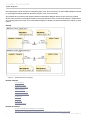
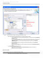
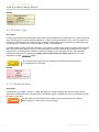
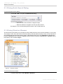
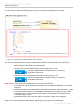
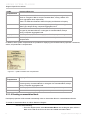
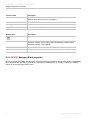
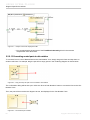
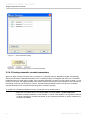
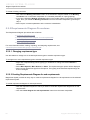
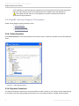
5.1.6 Using Structure Browser
The Structure browser allows you to browse for deep nested structures of the structure classifier in your model.
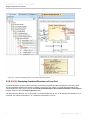
The property nodes, which are shown inside the property node (the parent property node), are the properties of
the classifier that type the parent property node. In the following figure, the node: diameter:m represents the
property: diameter:m of the classifier: Cylinder Liner and also the property: cylinderLiner : Cylinder Liner is
the property of the classifier: Engine.
Figure 4 -- Structure browser
To open the Structure browser
• From the main menu, select Window >Structure.
57
Copyright © 2009-2015 No Magic, Inc.
USING SYSML PLUGIN
Generic Procedures
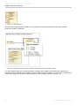
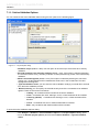
5.1.6.1 Specific display options
There are two specific display options:
• Display as Plain List
• Show Inherited Structure
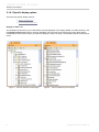
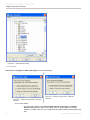
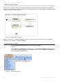
Display as Plain List
The classifiers of structure in your model will be normally displayed in a Package, Model, or Profile hierarchy. Use
the Display as Plain List option to show all classifiers of the structure in the model in the same level without
consideration of their owner. When you select the Display in Plain List option, the classifiers will be sorted by their
name.
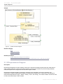
Figure 5 -- Structure standard normal display
58
Figure 6 -- Structure Browser plain list display
Copyright © 2009-2015 No Magic, Inc.
USING SYSML PLUGIN
Generic Procedures
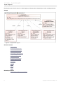
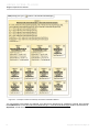
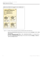
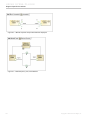
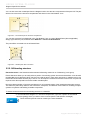
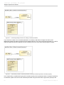
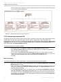
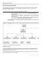
Show Inherited Structure
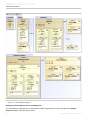
The Structure browser can show the properties that are inherited from the generalization classifier.
Figure 7 -- Four specialization classifiers of blocks
Figure 8 -- Inherited Structures of blocks
5.1.7 Generating SysML reports
This section contains only introductory information about the Report Wizard and SysML report templates. For
detailed information on how to use the Report Wizard engine, see the MagicDraw Report Wizard user guide.
59
Copyright © 2009-2015 No Magic, Inc.
USING SYSML PLUGIN
Generic Procedures
To create a report using a SysML report template
1. Select a report template and click Next in the Report Wizard dialog. The Select Report Data
pane will open. You can then select a predefined report data for the selected template (default =
Built-in).
2. You can modify the introductory information of a report, i.e. Variables (formerly called “User
Defined Fields”), by clicking the Variable button on the Select Report Data pane. The Variables
dialog will then display. You can then add/modify the variable of the report to be generated, such
as author, company name, company address, report purpose, report scope, etc. This information
will appear in the report generated.
3. Click OK to return to the Select Report Data pane. In the Select Report Data pane, click Next.
The Select Element Scope pane will then display.
4. In the Select Element Scope pane:
• Use the Add button to add an element selected in the element tree to the Selected
objects pane.
• Use the Add All button to add all elements directly owned by the element selected in
the element tree to the Selected objects pane.
• Use the Add Recursively button in to add all elements listed under the element
selected in the element tree to the Selected objects pane.
• Use the Remove button in to remove the selected element from the Selected objects
pane.
• Use the Remove All button in to remove all selected elements from the Selected
objects pane.
5. After the scope of the report is defined, click Next to proceed to the Output Options pane.
6. Specify the report file name, report file format, and image file format. It is recommended to use
RTF as the report file format.
7. Click Generate to create the report. Your report will be generated and automatically open in the
default document editor.
For more information about working with the Report Wizard, see the MagicDraw
ReportWizard UserGuide.pdf
5.1.8 Context-Specific Value Compartments
Context-Specific Value Compartments allows for
• creating different configurations for the same structure and display them directly in IBD diagram(s)
• having different values for the same part in different contexts
• assigning a different initial value to an inherited property
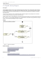
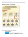
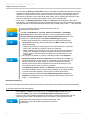
5.1.8.1 Progressive Reconfiguration
Progressive Reconfiguration enables SysML to handle a wide range of systems engineering configuration tasks.
Progressive Reconfiguration continuously applies the following values:
• Static class-level default values.
• Inherited Property-specific initial values.
• Redefined Property-specific initial values.
• Property-specific initial values.
Property-specific initial values are specific to the usage of a Block as a Part Property in a higher context (i.e.
another structured block or “assembly”). If there are many Part Properties of the same type, these Part Properties
may have different property-specific default values and will then be initialized differently.
60
Copyright © 2009-2015 No Magic, Inc.
USING SYSML PLUGIN
Generic Procedures
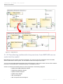
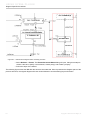
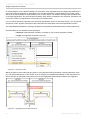
Property-specific initial values are managed by the higher-context structured block, which owns the Part
Properties that initialize or configure their (possibly different) values on instantiation. For example, the generic
capacity of a FuelTank (not any particular one) is 40 liters (class-level default value). For a vehicle, however, the
generic capacity of its FuelTank is 46 liters. An abstract Vehicle block will thus configure its tank:FuelTank part
property by initializing it with a new capacity value. This can be done with Progressive Reconfiguration that will
assign the instance specification tank:FuelTank to the property tank:FuelTank of the Vehicle block.
Figure 9 -- Progressive reconfiguration
For more information about Progressive Reconfiguration, see http:/
/training.nomagic.com.
5.1.8.2 Deep Reconfiguration
Deep Reconfiguration enables you to configure deep-nested part(s) with context-specific value(s). Consider, for
example, the case of a truck reusing a complex WheelHubAssembly for three pairs of wheels, each with different
characteristics. Although the basic WheelHubAssembly might be suitable for a range of vehicles (a car, touring
car, and minivan), it is not nearly suitable for a large truck. Some of the WheelHubAssembly parts and subparts
required for a truck are larger and must be stronger to handle heavy loads. They include:
• the diameter of the Tire, TireBead, and Rim will be larger.
• the inflationPressure value of the WheelAssembly will be higher.
• the LugBoltJoint will be subject to greater torque and boltTension.
• the LugBoltThreadedHole will have larger lugBoltSize and threadSize.
In this case, Progressive Reconfiguration will fail because the new configuration requirements “cascade”
throughout the entire complex WheelHubAssembly from the outermost context to the deepest part. Since no
61
Copyright © 2009-2015 No Magic, Inc.
USING SYSML PLUGIN
Generic Procedures
Progressive Reconfiguration approach can handle this deep reconfiguration of complex assemblies, you need to
use Deep Reconfiguration.
You can start with a completely new TruckWheelHubAssembly that configures a completely new
TruckWheelAssembly, right down to a TruckLugBoltJoint.
However, you could use, instead, SysML PropertySpecificType strategy, which is a set of “on-the-fly” extensions
(subtypes) of each Block used in a complex assembly hierarchy, to afford a point of redefinition of the Part
Properties and their Value Properties as required. See the ‘PropertySpecificType‘ section in OMG SysML
specifications.
For more information about Deep Reconfiguration, see http://
training.nomagic.com.
5.1.8.3 Context-Specific Value Compartments
The purpose of Context-specific Value Compartments is to show various values as a result of a reconfigured
selected context. In the FuelTank example (see "Progressive Reconfiguration"), the capacity of a FuelTank in a
Vehicle context is reconfigured to 46 litres. In the WheelHubAssembly example, (see "Deep Reconfiguration"),
the diameter of the Tire, Tire Bead and Rim, the inflationPressure of the WheelAssembly, etc., in a Truck
context will be reconfigured to suit the truck.
This section contains the following subsections:
• Using Context-Specific Value Compartments
• Displaying Context-Specific Value Compartments
• Selecting the Context of Context-Specific Value Compartments
• Customizing Context-Specific Value Compartment Display
• Value Propagation
You can see an example of a Deep Reconfiguration project by
opening context specific values.mdzip in the <md.install.dir>/
samples/SysML directory.
Using Context-Specific Value Compartments
A Context-Specific Value Compartment is a part symbol compartment. Only part symbols can have ContextSpecific Value compartments. A Context-Specific Value compartment displays the values of the properties (parts)
reconfigured in a selected context (Progressive or Deep Reconfiguration).
An example of Progressive Reconfiguration is when the values of y and z of a Location are reconfigured to 1 in
the Thing context. Thus, the “values (Thing)” compartment in the l:Location part (in the Thing package) will
display 1 as the values of y and z.
An example of Deep Reconfiguration is when the value of x of a Location in the UniverseContext package is
reconfigured to 3 in the UniverseContext context. Thus, the “values (UniverseContext)” compartment in the
l:Location part (in the t1:Thing part in the UniverseContext package) will display 3 as the value of x. If
UniverseContext is selected, the value of z, instead of x, will be reconfigured to 2.
62
Copyright © 2009-2015 No Magic, Inc.
USING SYSML PLUGIN
Generic Procedures
Figure 10 -- Block Definition Diagram
Displaying Context-Specific Value Compartments
You can display (or suppress) the Context-Specific Value Compartment of a part using either the Symbol
Properties dialog or the part shortcut menu.
63
Copyright © 2009-2015 No Magic, Inc.
USING SYSML PLUGIN
Generic Procedures
To display a compartment using the Symbol Properties dialog
• In the Symbol(s) Properties dialog, set the value of the Suppress Context Specific Values
symbol property under the Context Specific Values group to false by clearing the check box.
To suppress a compartment using the Symbol Properties dialog
• In the Symbol(s) Properties dialog, set the value of the Suppress Context Specific Values
symbol property under the Context Specific Values group to true by selecting the check box.
Figure 11 -- Symbol Properties dialog - Suppress Context Specific Values
To display a compartment using the part shortcut menu
• On the shortcut menu, clear the Suppress Context Specific Values option under the Context
Specific Values group.
To suppress a compartment using the part shortcut menu
• On the shortcut menu, select the Suppress Context Specific Values option under the Context
Specific Values group.
Selecting the Context of Context-Specific Value Compartments
The properties’ values shown in the Context-Specific Value Compartment of a part and the compartment label will
change according to the selected context. For example, if the selected context is A then the compartment label will
be values (A).
To select a context using the shortcut menu
• From the selected part’s shortcut menu, select Context Specific Values > Context.
64
Copyright © 2009-2015 No Magic, Inc.
USING SYSML PLUGIN
Generic Procedures
Customizing Context-Specific Value Compartment Display
You can display or hide the elements types in the Context-Specific Value Compartment of a part using either the
Symbol(s) Properties dialog or the part shortcut menu.
To display or hide element type using the Symbol(s) Properties dialog
1. Right-click the part and select the Symbol(s) Properties option.
2. Three display modes are available in the Symbol(s) Properties dialog:
• None: to hide types
• Name: to display the names of the element types
• Qualified Name: to display the qualified names of the element types
Figure 12 -- Symbol Properties dialog - Show Slot Type
To display or hide element type using the part shortcut menu
• From the selected part’s shortcut menu, select Show Slot Type, and then select a display mode.
Value Propagation
The Value Propagation mechanism enables values that are not overridden by the values from the selected context
in a Context-Specific Value Compartment to be displayed.
Assuming the property and the Value Propagation options are enabled, the value available in the next context will
be used to reconfigure the property if there is no value in the selected context to reconfigure the property.
However, if there is no value available in any context, the class-level default value will be displayed in the ContextSpecific Value Compartment, indicating that the property is not reconfigured at all.
See the following figure for an example of the Context-specific Values Compartments having the Value
Propagation enabled.
65
Copyright © 2009-2015 No Magic, Inc.
USING SYSML PLUGIN
Generic Procedures
Figure 13 -- BDD value propagate
In the UniverseContext package, only the value of x of a Location is reconfigured to 3 in the UniverseContext
context. The values of y and z are not set by the selected context. Since the value propagation is enabled, the next
66
Copyright © 2009-2015 No Magic, Inc.
USING SYSML PLUGIN
Generic Procedures
context, Universe, is considered. In the Universe context, the value of z is set to 2. However, the value of y is still
missing; therefore, the next context, Thing, is considered.
In the Thing context, the value of y is set to 1. Now, all attributes of the Location are set as follows:
• x=3
• y=1
• z=2
For more information about Value Propagation, see
http://training.nomagic.com.
To enable the value propagation mechanism
1. Click Options > Project on the main menu to open the Project Options dialog.
2. Select General project options > SysML.
3. Select the Propagate SysML Values check box and click OK.
Clear the Propagate SysML Values check box to disable the
Value Propagation mechanism.
5.1.9 Feature-based Compartments
SysML Plugin feature-based compartments allow you to display additional compartments in internal properties.
There are six feature-based compartments:
• :values
• :parts
• :references
• :constraints
• :properties (formerly :UML properties)
• :operations
• :flow properties
For any given property, these compartments will show information from the classifier of the property in conformity
with SysML specifications outlined in the ‘Compartment on Internal Properties’ section.
Figure 14 -- Compartments in block vs. Feature-based compartments in internal property
67
Copyright © 2009-2015 No Magic, Inc.
USING SYSML PLUGIN
Generic Procedures
For any property typed by a Block, feature-based compartments will contain the same information as that of the
compartments on the Block symbol, such as values, parts, references, constraints, UML properties, and
operations compartments.
5.1.9.1 Expanding and Suppressing Feature-based Compartments
You can expand or suppress feature-based compartments using either the Symbols Properties dialog or the
property shortcut menu.
Using the Symbol Properties Dialog of an Internal Property
To expand or suppress a feature-based compartments using the Symbol Properties dialog
1. Either right-click the property symbol and select Symbol(s) Properties or select the property and
press Alt + Enter. The Properties dialog opens.
2. In the SysML Internal Properties Compartments property group, do one of the following:
• Set the value of the corresponding symbol property to false by clearing the check box.
• Set the value of the corresponding symbol property to true by selecting the check box.
Figure 15 -- Symbol Properties dialog - SysML internal properties compartments
5.1.9.2 Displaying Options in Feature-based Compartments
Elements displayed in the feature-based compartments of a property can be customized using the symbol
properties listed under SysML Internal Attributes and SysML Internal Operations in the Symbol(s) Properties
dialog of each property.
68
Copyright © 2009-2015 No Magic, Inc.
USING SYSML PLUGIN
Generic Procedures
To customize the display of the elements in the feature-based compartments
• Select or clear any of the check boxes as shown in the following figure.
Figure 16 -- Symbol Properties dialog - SysML internal attributes and operations
5.1.10 NEW! Managing Element Groups
You can create and manage element groups, add, or remove group elements faster and more easily.
69
Copyright © 2009-2015 No Magic, Inc.
USING SYSML PLUGIN
Generic Procedures
Figure 17 -- Add element to group
5.1.11 NEW! Displaying Rake icon on symbol
You can use rake icon for faster navigation in the model. The rake icon on the symbol indicates that the
appropriate element has an internal structure. Double-click the element to open the internal diagram. The rake
icon is shown by default on the symbol.
To hide rake icon
1. Right-click the symbol.
2. Select Symbol Properties from shortcut menu or press Alt+Enter.
3. Set the Show Rake Icon property value to false.
70
Copyright © 2009-2015 No Magic, Inc.
USING SYSML PLUGIN
Generic Procedures
Figure 18 -- Using rake icon
5.1.12 Transferring mathematical expressions from MATLAB source
code into the model
MATLAB source code contains a functions declaration. The m-file is a text file containing a list of commands
written in MATLAB or Octave syntax. You can define functions and scripts in the m-file.
You can move the mathematical expressions from MATLAB source code into the model. Use the m-file to transfer
functions to a Constraint Block, Constraint Property, or Call Behavior Action.
Creation of elements from MATLAB source code is supported in the following diagrams:
• SysML Internal Block definition diagram
• SysML Block Definition diagram
• SysML Parametric diagram
• SysML Activity diagram
• UML Class diagram
• UML Composite Structure diagram
71
Copyright © 2009-2015 No Magic, Inc.
USING SYSML PLUGIN
Generic Procedures
• UML Activity diagram
The following figure illustrates the function declaration in m-file. It is for least-square fitting to find the slope (m)
and the y-intercept (b) of a straight-line equation from two given input parameters x and y. The constraint
expression is: [m, b] = linefit(x, y). The constraint parameters are: x, y, m, and b. After the function transfer into the
element, its type, property, and parameter are set automatically and are displayed on the element shape.
Figure 19 -- Creating Constraint Block, Constraint Property, or Call Behavior Action from MATLAB source code
The name of the created element is the same as the name of the function in the m-file. If the name of that element
already exists, the name duplicates with incremental number at the end of the name.
Figure 20 -- Element name duplication with incremental number
72
Copyright © 2009-2015 No Magic, Inc.
USING SYSML PLUGIN
Generic Procedures
If m-file contains multiple functions declarations, only the first function is transfered into the model.
Figure 21 -- Transferring m-file with multiple functions declaration
Use one of the following ways to transfer the mathematical expressions from MATLAB source code into the
model:
• NEW! Drag the m-file directly to the diagram pane.
• Drag the m-file onto the already existing element shape (empty or full).
The Activity diagram does not support this way of transferring
mathematical expressions.
• Use shortcut menu on the already existing element shape (empty or full).
The Activity diagram does not support this way of transferring
mathematical expressions.
NEW! Drag the m-file directly to the diagram pane to create one of the following:
• Constraint Block with its properties and parameters in the SysML Block Definition or UML Class
diagrams.
• Constraint Property and Constraint Block in the SysML Internal Block, SysML Parametric, or UML
Composite Structure diagrams. Constraint Block automatically is set as type for newly created
Constraint Property. The properties and parameters of Constraint Block are displayed on the
Constraint Property shape.
• Call Behavior Action with its pins and opaque in the SysML or UML Activity diagrams.
Drag the m-file onto the already existing element shape (empty or full) to set one of the following:
73
Copyright © 2009-2015 No Magic, Inc.
USING SYSML PLUGIN
Diagram Specific Procedures
• Constraints and parameters for Constraint Block in the SysML Block Definition or UML Class
diagrams.
• Type for Constraint Property by creating new the Constraint Block in SysML Internal Block, SysML
Parametric, or UML Composite Structure diagrams. The properties and parameters of newly
created Constraint Block are displayed on the Constraint Property shape.
To transfer the mathematical expression into the Constraint Block or Constraint Property
1. In the Containment tree or on the diagram pane, select a Constraint Block or Constraint Property
(with set type).
2. From the shortcut menu, choose Tools > Create Expression from M-File. The Open file dialog
opens.
3. Select the m-file and click Open.
The constraints and parameters are set for Constraint Block.
Related diagrams
SysML Block Definition Diagram (BDD)
SysML Internal Block Diagram (IBD)
SysML Parametric Diagram
SysML Activity Diagram
Related external resources
“Class Diagram” in “Magic Draw UserManual.pdf”
“Composite Structure Diagram” in “Magic Draw UserManual.pdf”
“Activity Diagram” in “Magic Draw UserManual.pdf”
5.2 Diagram Specific Procedures
• SysML Block Definition Diagram Procedures
• SysML Internal Block Diagram Procedures
• SysML Package Diagram Procedures
• SysML Parametric Diagram Procedures
• Requirements Diagram Procedures
• SysML Activity Diagram Procedures
• SysML Use Case Diagram Procedures
• SysML Sequence Diagram Procedures
5.2.1 SysML Block Definition Diagram Procedures
SysML Block Definition Diagram specific features include:
• Inserting a new SysML property
• Inserting a new SysML diagram
• Using SysML-Style compartments
• Creating an association block
• Creating a SysML Internal Block Diagram
• Representing association roles as block properties
74
Copyright © 2009-2015 No Magic, Inc.
USING SYSML PLUGIN
Diagram Specific Procedures
• NEW! Managing Interfaces of the Block
• NEW! Managing Block properties
5.2.1.1 Inserting a new SysML property
You can create a SysML property in the following ways:
• Block shortcut menu
• Block Smart Manipulator menu
To create a SysML property
1. Do one of the following:
• Select a block and from its shortcut menu, select Insert New SysML Property.
• On a selected block, click the Insert SysML property button.
2. Select a SysML property you want to create.
For more information on SysML properties, see the "SysML Block Definition Diagram (BDD)" section.
You can also use the Block shortcut menu to create a new UML property or UML
operation. For more information see MagicDraw UserManual.pdf.
The Block smart manipulator menu will not be displayed after you have created a new
stereotype as a subtype of a Block unless you save and restart your project first.
75
Copyright © 2009-2015 No Magic, Inc.
USING SYSML PLUGIN
Diagram Specific Procedures
5.2.1.2 Inserting a new SysML diagram
To create a SysML diagram with a Block as its owner
• From the selected Block shortcut menu, select New Diagram and then select a diagram you want
to create.
5.2.1.3 Using SysML-Style compartments
SysML Specifications allow Blocks to have multiple compartments. SysML plugin provides five independent,
compatible block compartments:
• parts
• references
• values
• constraints
• property’s compartments
Figure 22 -- SysML block compartments
SysML
Compartments
Displayed Elements
parts
Part Properties: properties which are typed by Blocks or subtypes of Block,
except Constraint Block, having ‘composite’ aggregation kind.
Any Part property automatically becomes a reference property if aggregation
kind is set to “shared” or “none”.
76
Copyright © 2009-2015 No Magic, Inc.
USING SYSML PLUGIN
Diagram Specific Procedures
SysML
Compartments
Displayed Elements
references
Shared Properties and Reference Properties are the properties typed by
Blocks or subtypes of Block, except Constraint Block, having ‘shared’ and
‘none’ aggregation kind, respectively.
There is no distinction between Shared Property and Reference Property.
values
Value Properties: properties which are typed by Value Types or subtypes of
Value Type, always having ‘composite’ aggregation kind.
constraints
Constraints and Constraint Properties. Constraint Properties: properties which
are typed by Constraint Blocks, or subtypes of Constraint Block, always
having ‘composite’ aggregation kind.
flow properties
Flow Properties: properties which apply the «FlowProperty» stereotype.
properties
All other properties which cannot be classified into the previous
compartments.
In addition, three SysML compartments are provided for displaying the Constraint Block properties: constraints,
others, and parameters’ compartments.
Figure 23 -- SysML constraint block compartments
SysML
Compartments
Displayed Elements
constraints
Constraints and Constraint Properties. Constraint Properties are properties
that are typed by Constraint Blocks, or subtypes of a Constraint Block, always
having ‘composite’ aggregation kind.
others
All other properties that cannot be classified into the previous compartments.
parameters
Constraint Parameters (reusing the ‘ports’ compartment of a Class).
5.2.1.4 Creating an association block
Participant properties will be created automatically when an Association Block is created between Blocks.
To create an Association Block in a Block Definition Diagram
1. Do one of the following:
• From the diagram panel, select Association Block. On the diagram pane, select a
Block to be used as the source of the to-be-created Association Block.
77
Copyright © 2009-2015 No Magic, Inc.
USING SYSML PLUGIN
Diagram Specific Procedures
• Select the Association Block icon on the Smart Manipulator menu of a Block to be
used as the source of the Association Block.
2. Select a target of the Association Block by either selecting an existing Block on the diagram to be
used, or clicking on empty space on the diagram to create such target Block.
3. An Association Block will then be created between the source and target Blocks.
5.2.1.5 Creating a SysML Internal Block Diagram
To create a SysML Internal Block diagram for a Block
1. Select the Block symbol. The smart manipulator menu will appear.
2. Click the SysML Internal Block diagram button
. The SysML Internal Block diagram will then
be created and owned by the selected block.
3. The SysML Internal Block diagram and the owner block will have the same name. The hyperlink to
the created diagram will be added to the selected block.
5.2.1.6 Representing association roles as block properties
When a Block is represented in the other BDD diagrams, all Association roles will be represented in the Block
properties compartment as normal properties. This representation option for Association roles is enabled by
default in all new SysML projects. This option, however, does not apply to any existing projects you may already
have.
Figure 24 -- Association Role is represented as normal property
5.2.1.7 Creating instances of blocks with complex structure
Creating instances for a complex model can be quite difficult, especially, since instances are frequently used in
SysML (unlike in UML), in particular when assembling systems. Starting with version 16.5, a new feature has been
included: Automatic Instantiation.
The purpose of this feature is to provide a wizard for automatic instantiation of the composite structures of a
system or system parts. Instances are widely used in simulation environments, for example, ParaMagic, and also
for defining different system configurations and test cases.
The following two samples will describe how to use the Automatic Instantiation feature.
To automatically instantiate a Block
1. Right-click a Block and select Tools > Create Instance on the shortcut menu. The Automatic
Instantiation Wizard opens.
2. Follow the steps of the wizard.
3. Click Finish to create the instance specifications and diagram. The Instance specifications will be
created and displayed in the chosen diagram.
78
Copyright © 2009-2015 No Magic, Inc.
USING SYSML PLUGIN
Diagram Specific Procedures
Figure 25 -- Example of instance created by Automatic Instantiation Wizard
You can reassign some values, for example, if you like to use “SuperFuel” for “fuelReturn” instead, then reassign
the fuelReturn slot in the HSU.internalCombustionEngine : InternalCombustionEngine instance specification to
SuperFuel, a Fuel kind with a specific fuelPressure.
79
Copyright © 2009-2015 No Magic, Inc.
USING SYSML PLUGIN
Diagram Specific Procedures
Figure 26 -- Changing slot value of “fuelReturn” property
80
Copyright © 2009-2015 No Magic, Inc.
USING SYSML PLUGIN
Diagram Specific Procedures
Figure 27 -- Instances after changing slot value of “fuelReturn” property
Case Study:
To automatically instantiate a Block to be used with ParaMagic Plugin
1. Right-click a block and select Tools > Create Instance on the shortcut menu. The Automatic
Instantiation Wizard opens.
Note that ParaMagic sample projects are available in the
<md.install.dir>/samples/ParaMagic directory after you installed
ParaMagic Plugin. The Satellite.mdzip sample here is used to
demonstrate how this feature works.
81
Copyright © 2009-2015 No Magic, Inc.
USING SYSML PLUGIN
Diagram Specific Procedures
2. In Step 1, select the required properties as shown in the following figure and set the value for each
value property of the instantiate classifier.
3. Click Next.
Figure 28 -- Automatic Instantiation Wizard - Step 1.Select parts
4. In Step 2, create a new package named SatelliteInstance02 and click Next.
82
Copyright © 2009-2015 No Magic, Inc.
USING SYSML PLUGIN
Diagram Specific Procedures
Figure 29 -- Automatic Instantiation Wizard - Step 2.Select a package
5. In Step 3, type: SatInstance02BDD in the Type diagram name box, and select BDD as the
diagram type.
83
Copyright © 2009-2015 No Magic, Inc.
USING SYSML PLUGIN
Diagram Specific Procedures
Figure 30 -- Automatic Instantiation Wizard - Step 3.Select a diagram
6. Click Finish. The SatInstance02BDD diagram will be created.
84
Copyright © 2009-2015 No Magic, Inc.
USING SYSML PLUGIN
Diagram Specific Procedures
Figure 31 -- Example of instance created with Automatic Instantiation Wizard with initialized slots
7. Right-click the SatelliteInstance02 package in the browser and select ParaMagic > Util > Create
CXI_heading.
8. Right-click again and select ParaMagic > Util > Add default causalities. The package will then
be ready for ParaMagic Plugin.
9. Right-click the SatelliteInstance02 package in the browser and select ParaMagic > Browse to
open the ParaMagic browser.
85
Copyright © 2009-2015 No Magic, Inc.
USING SYSML PLUGIN
Diagram Specific Procedures
Figure 32 -- ParaMagic browser
10. You can then use this browser to calculate the values of the properties. For more information on
how to use this browser, see ParaMagic User Manual.
For more information about using the Automatic Instantiation
Wizard, see Automatic Instantiation Wizard chapter in
MagicDraw UserManual.pdf.
5.2.1.8 SysML callout box
To create a callout box showing the attributes, constraints, and tag values of an element
1. Do one of the following:
• Create an anchored Note to the symbol of element on the diagram using the anchor
button on the smart manipulator.
• Create a Note by using the diagram toolbar and create anchor line to the symbol of
element.
2. Either:
• Click Edit compartment of anchored Note using the smart manipulator button on a
Note.
• Select the context menu items in Edit Compartment menu group.
86
Copyright © 2009-2015 No Magic, Inc.
USING SYSML PLUGIN
Diagram Specific Procedures
Figure 33 -- Edit Compartment manipulator button
3. The Compartment Edit dialog will open.
Figure 34 -- Compartment Edit dialog
4. Select the element properties, constraints, and tagged values that you want to show in the callout
box. Then click OK to close the dialog.
5. Select Show Tagged Values on the context menu of Note symbol to show the selected tagged
values in the callout box.
Figure 35 -- Callout box with SysML callout style
6. You can customize the way the callout box looks using the Symbol Properties dialog of Note
symbol.
• SysML Callout Style symbol property can be used to switch between MagicDraw
standard callout style and the SysML callout style. By default, this property is set to
true for the SysML project. With SysML callout style, the element types (for example,
«block», «connector», «atomicFlowPort», and «part») will be shown instead of the icon
of the tagged values which are the model elements.
87
Copyright © 2009-2015 No Magic, Inc.
USING SYSML PLUGIN
Diagram Specific Procedures
• SysML Element Type symbol property can be used to show or hide the element types
in the callout box when it is displayed with SysML callout style.
Figure 36 -- Symbol Properties dialog of callout box
The new callout notation applies to all types of SysML diagrams.
88
Copyright © 2009-2015 No Magic, Inc.
USING SYSML PLUGIN
Diagram Specific Procedures
5.2.1.9 NEW! Managing Interfaces of the Block
All owned and inherited Ports and their Interfaces of the selected Block are collected on the left of the Block
Specification window > Ports/Interfaces. Manage them by creating, redefining or deleting.
Figure 37 -- Block Specification window. Ports/ Interfaces node
89
Copyright © 2009-2015 No Magic, Inc.
USING SYSML PLUGIN
Diagram Specific Procedures
Column name
Description
Direction
Direction prefix of the Port. The tilde symbol (~) appears before the
direction prefix when the Port is conjugated.
Port Name
Name of the Port.
Port Type
Type of the Port.
Type Features
Features of the Port type
Button name
Description
Opens the Specification window of the selected Port.
Create
Opens the list with the available to create properties. Click to create the
Connector property, Part property, Reference property, Value property,
Constraint property, Flow property.
Redefine
Duplicates the selected item and marks its name in ascending order.
Delete
Removes the selected item from the list.
5.2.1.10 NEW! Managing Block properties
All owned and inherited Block properties are collected on the left of the Block Specification window > Properties.
Block properties are grouped as in the Block compartments. Manage them by creating, redefining or deleting
directly in the General Specification pane.
90
Copyright © 2009-2015 No Magic, Inc.
USING SYSML PLUGIN
Diagram Specific Procedures
Figure 38 -- Block Specification window. Properties node
Column name
Description
Name
Property name.
Type
Property type.
Default Value
Property default value.
Owner
Block name that contains the current property.
Button name
Description
Opens the Specification window of the selected property.
Create
Opens the list with the available to create properties. Click to create the
Connector property, Part property, Reference property, Value property,
Constraint property, Flow property.
Redefine
Duplicates the selected item and marks its name in ascending order.
91
Copyright © 2009-2015 No Magic, Inc.
USING SYSML PLUGIN
Diagram Specific Procedures
Button name
Description
Delete
Removes the selected item from the list.
5.2.2 SysML Internal Block Diagram Procedures
The SysML IBD specific features include:
• Creating Ports
• Displaying Parts
• Displaying Ports
• NEW! Displaying Direction Prefixes of Proxy and Full Ports
• NEW! Displaying Combined Direction on Proxy Port
• NEW! Displaying Direction Prefixes of Flow Property
• Using Edit Compartment
• Show Default Value and Show Slot Type
• Provided/Required Interfaces
• NEW! Managing Interfaces of the Proxy Port
• Create Directed Features and Specify Feature Directions
• Displaying Structures of Blocks in Compartments and IBDs
5.2.2.1 Creating Ports
You can easily create full and proxy ports.
A full port is a part on a boundary. You can now easily convert your parts into full ports by dragging them to the
diagram frame. All ports, connectors, other information, including the layout will remain unchanged.
To convert a part to the full port
1. Select a part and drag it to the diagram frame.
2. When the diagram frame is highlighted, release the part. The full port is created on the diagram
frame.
When the full port is created on the diagram frame, you cannot drag
it back (except Undo the conversion).
92
Copyright © 2009-2015 No Magic, Inc.
USING SYSML PLUGIN
Diagram Specific Procedures
Figure 39 -- Part converted to full port
To create a proxy port
1. Select a part or a port on the part and from the smart manipulator toolbar select Connector.
2. Attach a connector to any part or diagram frame. The appropriate port is created.
Figure 40 -- Creating proxy port
5.2.2.2 Displaying Parts
If you have already defined the parts (properties) of a Block, you can then display the parts on any IBD, having the
Block as its context.
93
Copyright © 2009-2015 No Magic, Inc.
USING SYSML PLUGIN
Diagram Specific Procedures
To display parts in IBD
1. Right-click IBD and select Related Elements > Display Parts. All the parts selected will be listed
in the Select Parts dialog.
Figure 41 -- Select Parts dialog
2. Select parts and click OK to show the selected parts on the IBD.
5.2.2.3 Displaying Ports
If you have already defined the port(s) / flow port(s) of a Block, you can then display the port(s) / flow port(s) / full
port(s) / proxy port(s) on any part typed by the Block.
To display ports / flow ports on a part on an IBD
1. Do one of the following:
• Select Related Elements. If the type (classifier) of the part owns at least one port/flow
port, the Display Ports option will be enabled for you to select. Select this option.
• Click the Display Ports icon on the Smart Manipulator menu of the part.
Figure 42 -- Property smart manipulator menu to display ports
2. All ports (including flow ports) will then be listed in the Select Ports dialog.
3. Click OK to view the selected (checked) port(s) on the part symbol.
94
Copyright © 2009-2015 No Magic, Inc.
USING SYSML PLUGIN
Diagram Specific Procedures
Figure 43 -- Select Ports dialog
4. The selected ports will then be displayed on the part symbol.
5.2.2.4 NEW! Displaying Direction Prefixes of Proxy and Full Ports
Directions of Proxy and Full Ports can be identified with help of direction prefixes.
The Proxy Port direction prefixes are displayed:
• On Blocks (1). To hide the Proxy Port direction prefixes on the Block, set the Show Proxy Port
Direction in Compartment property value to false in the Symbol Properties dialog of that Block.
The Proxy and Full Port direction prefixes are displayed:
• In the Model Browser (2).
• On the Port shape when its name is displayed inside the shape (3). For this, open the Symbol
Properties dialog of the Proxy or Full Port and select Name and Type Labels Inside or All
Labels Inside as the Position of Labels property value. To hide the direction prefix on the Port
shape, set the Show Direction Prefix Inside Port property value to false in the Symbol
Properties dialog of that Port.
• On the ToolTip which opens when you move the pointer over the Proxy or Full Port or their names
(4).
95
Copyright © 2009-2015 No Magic, Inc.
USING SYSML PLUGIN
Diagram Specific Procedures
Figure 44 -- Places of displaying Proxy or Full Port’s direction prefixes
5.2.2.5 NEW! Displaying Combined Direction on Proxy Port
Combined direction consists of all owned and inherited flow properties and directed features of the Proxy Port.
The flow properties direction are shown by default on the Proxy Port shape. To include directed features into
combined direction of the Proxy Port set the Include Directed Features into Combined Direction of Proxy Port
property value to true in the Project Options dialog.
If all features have direction "out" or "provided", the combined direction is "out". If all features have direction "in" or
"required", the combined direction is "in". Otherwise the direction is "inout".
96
Copyright © 2009-2015 No Magic, Inc.
USING SYSML PLUGIN
Diagram Specific Procedures
Figure 45 -- Proxy Port’s combined direction including directed features
5.2.2.6 NEW! Displaying Direction Prefixes of Flow Property
Directions of flow property can be identified with help of direction prefixes.
The flow property direction prefixes are displayed:
• On Parts (1). To hide flow property direction prefix on the Part, set the Show Flow Property
Direction in Compartment property value to true in the Symbol Properties dialog of that Part.
• In the Model Browser (2).
Figure 46 -- Places of displaying flow property’s direction prefixes
5.2.2.7 Using Edit Compartment
You can customize elements to be displayed in the various compartments of a part. Such compartments include
Constraints, Tagged Values, Default Value, Structure, and many more.
To customize a compartment of a part
1. Right-click a part and select Edit Compartment on the shortcut menu.
97
Copyright © 2009-2015 No Magic, Inc.
USING SYSML PLUGIN
Diagram Specific Procedures
2. Select a compartment to be customized. The Compartment Edit dialog will open.
3. In the Compartment Edit dialog, move an element from the All: to the Selected: box to display
the element.
4. Click OK when done.
Figure 47 -- Compartment Edit dialog
5.2.2.8 Show Default Value and Show Slot Type
Use Show Default Value to display the default value of a part. If the default value is an Instance Specification, the
defaultValue compartment containing the Instance Specification slots will be displayed on the part instead. In this
case, you can use Show Slot Type to display the types of the slots) in the compartment.
Show Default Value
To display the default value of a part (property)
1. Right-click a part or property and select Show Default Value (if it already has a default value) on
the shortcut menu.
If the property has no default value, drag an instance with slot(s) to the property symbol. The
instance will then be assigned as the default value for this property, and its slots with values
will be displayed inside the property symbol.
2. The default value of the property will be displayed. If the default value is an Instance Specification,
the defaultValue compartment containing the Instance Specification slot(s) will be displayed
instead.
Figure 48 -- defaultValue compartment
98
Copyright © 2009-2015 No Magic, Inc.
USING SYSML PLUGIN
Diagram Specific Procedures
Show Slot Type
Use the Show Slot Type shortcut menu to display the slot types in the defaultValue compartment of a property,
having an Instance Specification as its default value:
To display the slot types of a part
1. Right-click a property and select Show Slot Type on the shortcut menu. Three Show Slot Type
options will be available on the shortcut menu
• None (no type slot will be displayed)
• Name
• Qualified Name
2. If you select Name or Qualified Name, the slot types will be displayed.
Figure 49 -- defaultValue compartment with slot types
5.2.2.9 Provided/Required Interfaces
Provided/Required Interfaces help identify compatible ports that can be connected together in an IBD. On a port,
you can
• create a new Provided/Required Interface using the port specification dialog, or
• display an existing Provided/Required Interface using the port shortcut menu.
Creating New Provided/Required Interfaces Using the Port Specification Dialog
To create new Provided/Required Interface of a port
1. Do one of the following:
• Right-click a port to open its shortcut menu, and then select Specification to open the
Specification dialog. Then, select the Provided/Required Interfaces group to open
the Provided/Required Interfaced pane.
Figure 50 -- Port Smart Manipulator Menu - Provided/Required interfaces
• Click a port in a diagram to open its smart manipulator menu, and then select the
Provided/Required interfaces icon to open the Provided/Required Interfaced pane.
99
Copyright © 2009-2015 No Magic, Inc.
USING SYSML PLUGIN
Diagram Specific Procedures
Figure 51 -- Port Specification window, Provided/Required Interfaces group
Only typed ports can realize / use interfaces.
2. Click Add and then select either Provided or Required.
Case Study #1:
If the port is typed, the Select Interface dialog will open. You can either:
• select any of the existing interfaces (and flow specifications) to be used as the
Provided / Required Interface of the port, or
• click Create to create a new interface. The interface specification dialog will then be
displayed, prompting you to type in its name. The new interface will then be used as
the Provided / Required Interface of the port.
100
Copyright © 2009-2015 No Magic, Inc.
USING SYSML PLUGIN
Diagram Specific Procedures
Figure 52 -- Select Interface dialog
Case Study #2:
If the port is not typed, the Select Port Type menu will then display.
Figure 54 -- Select Port Type menu - Required
Interface
Figure 53 -- Select Port Type menu - Provided
Interface
You can then select:
• (For Provided Interface only) Set provided interface as port type. The Select
Interface dialog will then open. In the dialog, you can either choose an existing
interface or create a new one, to be used as the Provided Interface and the type of the
port.
101
Copyright © 2009-2015 No Magic, Inc.
USING SYSML PLUGIN
Diagram Specific Procedures
• Create “dummy” port type automatically. The Select Interface dialog will then
open. In the dialog, you can either choose an existing interface or create a new one, to
be used as the Provided or Required Interface of the port. In addition, a dummy
classifier, realizing (for Provided) or using (for Required) the interface, will be
automatically created and used as the type of the port.
• Select or create port type manually. The Select Port Type dialog will then open. You
can then choose a classifier to be used as the type of the port. Click OK, the Select
Interface dialog will then open. In the dialog, you can either choose an existing
interface or create a new one, to be used as the Provided or Required Interface of the
port. In addition, a Realization (or Usage) dependency will be automatically created
from the port type to the Provided (or Required) Interface of the port.
Figure 55 -- Select Port Type dialog for Provided / Required interface
Displaying Existing Provided/Required Interfaces
To display the existing Provided/Required Interface of a port
1. Right-click a port to open its shortcut menu and do one of the following:
• select Show Required Interfaces or Show Provided Interfaces
• select Related Elements > Display Provided/Required Interfaces
2. The Required / Provided Interfaces will be displayed on the port, in the form of ball-socket
(lollipop) notation.
102
Copyright © 2009-2015 No Magic, Inc.
USING SYSML PLUGIN
Diagram Specific Procedures
Figure 56 -- IBD with required and provided interfaces displayed
Figure 57 -- BDD with parts, ports, and interfaces
103
Copyright © 2009-2015 No Magic, Inc.
USING SYSML PLUGIN
Diagram Specific Procedures
5.2.2.10 NEW! Managing Interfaces of the Proxy Port
The detailed information about Proxy Port interface is collected on the left of the Port Specification window>
Interface Block Properties.
Figure 58 -- Proxy Port Specification window. Interface Block Properties Node
Column name
Description
Name
Compartment name.
Type
Compartment type.
Default Value
Use to set the value manually.
Owner
Interface Block which is the owner of the selected Proxy Port.
Button name
Description
Opens the Specification window of the compartment
Up
Move item to upper position in the list. The items are automatically
renumbered after moving.
Down
Move item to lower position in the list. The items are automatically
renumbered after moving.
Create
Opens the list with the available to create properties. Click to create the
Value property, Flow property or Reference property.
Redefine
Duplicates the selected item and marks its name in ascending order.
Delete
Removes the selected item from the list.
104
Copyright © 2009-2015 No Magic, Inc.
USING SYSML PLUGIN
Diagram Specific Procedures
5.2.2.11 Create Directed Features and Specify Feature Directions
The directed feature is a Feature element that applies the «DirectedFeature» stereotype. MagicDraw SysML
plugin provides the diagram context menu to specify the feature direction of the selected feature. When you set
the feature direction to the selected feature, it will apply the «DirectedFeature» stereotype automatically.
To specify a feature direction
1. Right-click a feature’s symbols owned by a block such as part, attribute, operation, and signal
reception.
2. Go to Feature Direction and select one of the directions of the feature.
5.2.2.12 Displaying Structures of Blocks in Compartments and IBDs
Composite Structure diagrams will not let you display the already-defined internal structures of Blocks reused as
parts in other structures (deep-nested structures). The same limitation exists when you need to modify or extend
existing structures in subtypes. Composite Structure diagrams will only let you display:
• Parts
• Nested parts
• Ports on the frame
• Ports on every part
• Paths for every part and port
Nested parts can be displayed with the dot notation in addition to using structure compartment. In the Display
Parts dialog, when only the nested part property of a class is selected, that class with the nested part property
selected will be displayed with the name of the class that contains the nested part property inside and the name of
the nested part, separated from each other with the dot notation.
105
Copyright © 2009-2015 No Magic, Inc.
USING SYSML PLUGIN
Diagram Specific Procedures
Figure 59 -- Nested part property selected and shown with its class and dot notation
Thus, to redisplay an internal structure in another structure, you have to recreate the internal structure manually.
The graphical layout must also be applied manually, making it a time-consuming activity.
106
Copyright © 2009-2015 No Magic, Inc.
USING SYSML PLUGIN
Diagram Specific Procedures
With the Display Internal Structure feature you can copy and paste (display) an existing structure diagram
defining a Block (Class) either in:
• The structure compartment of that Block, a subtype of that Block, a part typed by that Block, or a
part typed by a subtype of that Block, or
• Another diagram defining either a subtype of that Block or that Block itself.
With this feature, you can now display the already-defined internal structures of Blocks, reused as parts in other
structures (deep nested structures).
To redisplay a Block structure, already-defined in, at least, one structure diagram
1. Suppose there is the FrontWheelsAssembly IBD, having the FrontWheelsAssembly block as
its context.
2. Right-click the property and select Related Elements > Display Internal Structure from the
shortcut menu. Each IBD having either the type or a supertype of the type of the property as its
context will be available for you to select. For example, in the following figure, the
FrontWheelsAssembly IBD is available. Select it to display the structure of
FrontWheelsAssembly block in the property.
Figure 60 -- Sample of structure displayed in property
3. You can also display the structure in a new blank IBD, having the FrontWheelsAssembly block or
a subtype of the FrontWheelsAssembly block as its context, using the IBD shortcut menu.
107
Copyright © 2009-2015 No Magic, Inc.
USING SYSML PLUGIN
Diagram Specific Procedures
Figure 61 -- Sample of structure displayed in IBD
4. You can also display the structure of the FrontWheelsAssembly block in the structure
compartment of the block itself.
5.2.2.13 Converting nested parts to dot notation
To convert a Part or a set of Nested Parts to the “Dot Notation” form, simply drag such Parts and drop them on
another valid view. For example, drag the part d:D to empty space in the containing diagram as shown below.
Figure 62 -- Drag and drop the part to be converted to dot notation
The confirmation dialog will be then open. Click the “Show in Path Notation” button to convert the Part to the “Dot
Notation” form.
Then, the part will be moved to the diagram canvas, and displayed in the “Dot Notation” form.
Figure 63 -- Dot notation part created
108
Copyright © 2009-2015 No Magic, Inc.
USING SYSML PLUGIN
Diagram Specific Procedures
You can also move the created part from the diagram back to the structure compartment of the part b:B. The part
will then be moved to the structure compartment and shown in the “Dot Notation” form.
Figure 64 -- Dot notation part in Structure compartment
You can also convert a Part displayed in the “Dot Notation” form to a set of Nested Parts (where applicable).
Simply right-clicks the part, and then select Refactor > Convert to Nested Parts.
The part will be converted to a set of Nested Parts.
Figure 65 -- Nested parts after conversion
5.2.2.14 Extracting structure
Extract Structure is the first advanced automated refactoring method in our “Refactoring” tools group.
Extract Structure allows you to easily select a portion of an existing system structure and transform it into another
reusable Block (or Subsystem) which may then be used as parts in many other structures. In addition to this, the
Extract Structure feature can also play a 'move' or a 'decompose' role when a structure becomes too complex and
requires to be decomposed into several smaller reusable parts.
Recursive decomposition of structure and behavior is an important aspect of the iterative development process.
This feature is particularly useful for the automotive, aerospace, and defense communities for modeling complex
systems-of-systems and building reusable components.
To extract a new structure from an existing structure in a classifier
1. In an Internal Block Diagram or a structure compartment, right-click a portion of the internal
structure (part(s)) which you want to move or reuse (see the red selection rectangle).
These selected symbols must be owned by the same Classifier.
109
Copyright © 2009-2015 No Magic, Inc.
USING SYSML PLUGIN
Diagram Specific Procedures
Figure 66 -- Internal Block diagram before extracting structure
2. Select Refactor > Extract. The Extract Structure Wizard dialog will open, listing three steps to
extract a structure: Specify a new element, Create port(s), and Create a property.
3. Follow the steps of the wizard.
The following figure shows the IBD after the structure was extracted. Since it preserves the diagram space of the
previous structure, the original diagram will have minimal distortion and the existing layout will remain.
110
Copyright © 2009-2015 No Magic, Inc.
USING SYSML PLUGIN
Diagram Specific Procedures
Figure 67 -- Internal block diagram after extracting structure
You can check how the automatically-created new Block looks like by right-clicking the part and select Go To >
Type <name> to select the Block in the browser.
Open the created IBD to display the structure which was recently extracted. The structure view will be ready.
Figure 68 -- The created IBD of extracted classifier
111
Copyright © 2009-2015 No Magic, Inc.
USING SYSML PLUGIN
Diagram Specific Procedures
Figure 69 -- Displayed extracted structure
5.2.2.15 Creating a flow port
In general, a port / flow port should be defined in a BDD. However, you can also create a flow port on a part in an
IBD by using the IBD toolbar button.
To create a flow port on a part
1. Click the Flow Port button
either:
• on the IBD toolbar, or
• in the smart manipulator of the part.
2. If you click the Flow Port button on the IBD toolbar, select a part where the flow port will be
created. If you clicked the smart manipulator of the part, go directly to step 3.
112
Copyright © 2009-2015 No Magic, Inc.
USING SYSML PLUGIN
Diagram Specific Procedures
Figure 70 -- Flow port created on part
3. Select a port type in the Select Port Type dialog. The flow port will then be created, having an
‘inout’ direction.
4. You can change its direction using the port shortcut menu. Note that, without a direction, the flow
port will be just like a normal port (it will not enforce any direction on the item(s) flowing in/out of
the port).
The Flow Port direction must be defined.
ItemProperty
Item Property is the only attribute of Item Flow. An Item Flow describes the flow of items across a connector or an
association. If an Item Flow is assigned to a connector, in general, you can specify this optional attribute, Item
Property, to relate the flowing item to the instances of the connectors’ enclosing block.
In general, Item Flows (and Item Property) are defined on connectors in IBDs.
To create an Item Flow having the Item Property tag initialized on a connector
1. Do one of the following:
• click the Item Property button on the IBD diagram toolbar, and then select the
connector, or
• click the Item Property icon on the connector smart manipulator menu, or
• drag the property, which will be used as the item property, to the connector.
2. The Item Flow / Item Property dialog will then open.
113
Copyright © 2009-2015 No Magic, Inc.
USING SYSML PLUGIN
Diagram Specific Procedures
Figure 71 -- Item Flow / Item Property dialog
3. The existing item flows on the selected connector can be selected for setting the item property
using the Item Flow drop-down menu. The item flows, whose realizing connector property
contains the selected connector, will be listed in this drop-down menu.
Figure 72 -- Item Flow / Item Property dialog - Item Flow selection
4. You can also create a new item flow by selecting <NEW> in the drop-down menu.
5. In the Item Flow / Item Property dialog, you can also choose the direction of the Item Flow from
the Direction drop-down menu.
114
Copyright © 2009-2015 No Magic, Inc.
USING SYSML PLUGIN
Diagram Specific Procedures
Figure 73 -- Item Flow / Item Property dialog - Direction selection
6. Click the browse button “…” next to the Conveyed Classifiers box. The Select Conveyed
Classifier dialog will open.
7. Select a classifier to be used as the Conveyed Classifier and click OK.
Figure 74 -- Select Conveyed Classifiers dialog
8. Click the browse button “…” next to the Item Property box. The Select Item Property dialog will
open.
9. Select a part (property) to be used as the Item Property and click OK.
115
Copyright © 2009-2015 No Magic, Inc.
USING SYSML PLUGIN
Diagram Specific Procedures
Figure 75 -- Select Item Property dialog
10. Click OK in the Item Flow / Item Property dialog. An Item Flow having the selected property as
its Item Property will be created on the connector.
You can create a new conveyed classifier either on a new item flow or
on an existing item flow by dragging the classifier to a connector or
association. The dragged classifier will be a conveyed classifier of the
item flow.
5.2.3 SysML Package Diagram Procedures
• Using package element
5.2.3.1 Using package element
You can display the name of a package either on top of it or on its tab.
To display a package name
1. Right-click a package and select Header Position on the shortcut menu.
2. Select either:
• Top to display the package name on top
• In Tab to display it in the tab
You can also show a list of elements owned by a package.
To show an element list
1. Right-click a package and select Show Elements List on the shortcut menu.
2. The elements owned by the package will then be displayed in the package.
116
Copyright © 2009-2015 No Magic, Inc.
USING SYSML PLUGIN
Diagram Specific Procedures
Figure 76 -- List of elements
5.2.4 SysML Parametric Diagram Procedures
SysML Parametric Diagram features include Display Parameters and the other six specific features similar to
IBD. They are as follows:
• Displaying parameters
• Creating automatic constraint parameters
• Creating a binding connector
For more information on the above six features, see the SysML Internal Block Diagram Procedures section.
5.2.4.1 Displaying parameters
This feature enables you to display the constraint parameters of a constraint block on a Constraint Property typed
by the Constraint Block.
To display constraint parameters
1. Do one of the following:
• Select Display Parameters on the property shortcut menu.
• Click the Display Parameters icon on the property smart manipulator.
2. The Select Parameters dialog will open and the constraint parameter(s) owned by the type of the
constraint property will be listed in the dialog.
3. Select constraint parameters to be shown on the constraint property symbol. The selected
constraint parameters will be displayed as small square boxes.
117
Copyright © 2009-2015 No Magic, Inc.
USING SYSML PLUGIN
Diagram Specific Procedures
Figure 77 -- Select Parameters dialog
Figure 78 -- Constraint property with its constraint parameters
5.2.4.2 Creating automatic constraint parameters
When you drag a binding connector from a property to a constraint property, MagicDraw SysML automatically
shows a list of hidden constraint parameters in the constraint property and suggest new names for a constraint
parameters that you might want to create. If the constraint parameter you want to connect does not exist, you can
create it on the spot. The suggested parameter names come from the names of the properties on the other end of
the binding connector you are trying to connect, and the extracted variable names come from the constraint
expressions defined in a constraint block that types the constraint property.
To create new constraint parameters from the context menu of a constraint block
1. Right-click a constraint block, for example Sum, and select Tools > Create Parameters.
2. Create a constraint parameter, in this example, 'z', which is the variable in an expression that has
not been created as a constraint parameter. A new constraint parameter ‘z’ will be created in the
constraint block Sum.
118
Copyright © 2009-2015 No Magic, Inc.
USING SYSML PLUGIN
Diagram Specific Procedures
Figure 79 -- New parameter
The following examples further illustrate how to create new constraint parameters with this new constraint
parameters creation mechanism.
Figure 80 -- Binding connector connects to defined constraint expression constraint property
In in the preceding figure, the constraint parameter a:Integer and b:Integer have already been defined in the
constraint block A. However, they are hidden on the constraint property Constraint 1:A. If you select a:Integer from
the list, the constraint parameter a:Integer will appear on the constraint property Constraint 1:A.
119
Copyright © 2009-2015 No Magic, Inc.
USING SYSML PLUGIN
Diagram Specific Procedures
Figure 81 -- Connecting binding connector to existing constraint parameter
If you choose to create a new constraint parameter, for example, select New c:Integer from the list, and
MagicDraw SysML will create and add it into the constraint block A. The name of the new parameter is c. It will be
typed by Integer because the opposite end of the binding connector is the value property typed by Integer.
Figure 82 -- Automatically created constraint parameter of defined constraint expression constraint property
In the case that the constraint block typing the constraint property has no parameter and the constraint expression
is undefined, SysML will create a new constraint parameter using the name and the type of the property at the
120
Copyright © 2009-2015 No Magic, Inc.
USING SYSML PLUGIN
Diagram Specific Procedures
opposite end of the binding connector. The created constraint parameter will be visible on the selected constraint
property with the binding connector attached.
Figure 83 -- Binding connector connects to undefined constraint expression constraint property
Figure 84 -- Automatically created constraint parameter of undefined constraint expression constraint property
5.2.4.3 Creating a binding connector
Binding connectors enable you to bind each constraint block parameter to the property of another block in the
surrounding context of that constraint block. Binding connectors are the only connectors allowed to bind constraint
parameters to the properties of other blocks.
121
Copyright © 2009-2015 No Magic, Inc.
USING SYSML PLUGIN
Diagram Specific Procedures
To create a binding connector
1. Click either the Binding Connector button on the Parametric diagram toolbar or the Binding
Connector icon on the smart manipulator of a constraint parameter or a part (property).
2. If you have clicked the Binding Connector button on the toolbar, select a part as the connector’s
origin, but if you clicked the Binding Connector icon from the smart manipulator, go directly to
step 3.
3. Select a part / constraint parameter as the connector’s destination.
5.2.5 Requirements Diagram Procedures
The Requirement Diagram procedures are as follows:
• Changing requirement type
• Creating Requirements Diagram for sub-requirements
• Numbering requirement IDs
• Using requirement element
For more information about creating, importing, and analyzing requirements, see
CameoRequirementsModelingPlugin UserGuide.pdf.
5.2.5.1 Changing requirement type
Use this feature to change one or several requirement types to another requirement type.
To change one or more requirement types to another requirement type
1. Right-click a requirement(s) whose type(s) you would like to change and select Refactor >
Convert To.
2. Select More Specific, More General, or Other. The requirement type options will be displayed.
3. Select a new requirement type from the options. The type(s) of the selected requirement(s) will
then be changed.
5.2.5.2 Creating Requirements Diagram for sub-requirements
MagicDraw SysML provides an easy way to create a requirements diagram for sub-requirements of the selected
requirement symbol.
To create requirements diagram for sub-requirements
1. Click the requirement symbol in which you want to create the requirements diagram for its sub-
requirements.
2. Click the Create diagram for sub-requirements button from the smart manipulator.
122
Copyright © 2009-2015 No Magic, Inc.
USING SYSML PLUGIN
Diagram Specific Procedures
3. The new requirements diagram for the sub-requirements will then be created with the same name
as that of the selected requirement.
Figure 85 -- Requirements Diagram for sub-requirements
5.2.5.3 Numbering requirement IDs
Numbering requirements is a trivial, time-consuming task, in particular, when working with a large SysML project.
SysML Plugin uses the DSL numbering engine, which is generic, highly flexible, and customizable. The
requirements numbering mechanism in SysML is the same as that in MagicDraw. Consequently the Requirement
ID Numbering menu has been changed to Element Numbering and the Requirement ID Numbering dialog has
been replaced with the Element Numbering dialog.
To edit the requirements numbering settings
1. On the main menu, click Options > Project. The Project Options dialog will open.
2. Select General project options from the list on the left-hand side. You will see the Numbering
options opens on the right-hand side.
3. You can select the Use Element Auto-numbering check box if you want SysML to number
requirements automatically and then select the Display Element Number check box if you want
requirement numbers appear before the requirements in the Containment tree.
4. Click OK.
Manual Numbering
To number a requirement or edit a requirement’s number using the Element Numbering dialog
1. Right-click a requirement in the Containment tree and select Element Numbering. The Element
Numbering dialog will open.
2. Select, for example, the HSUV Requirements package in the browser on the left-hand side of the
dialog. The requirements owned by the package will appear in the Requirements pane on the
right-hand side of the dialog.
3. In the Requirements pane, select the requirement(s). Use the Edit, Create/Remove, Increase,
Decrease, Renumber or Renumber Recursively buttons to number the selected requirements.
4. For example, if you click the Renumber button, the requirements under the package selected in
the browser on the left-hand side of the dialog will be renumbered using the predefined Separator,
Prefix, Numbering Scheme.
123
Copyright © 2009-2015 No Magic, Inc.
USING SYSML PLUGIN
Diagram Specific Procedures
5. You can click the Recursive Renumber button to renumber all requirements that are recursively
contained inside the selected node. The Numbering Scheme, Prefix, and Separator, which are
defined in the selected node, will be used for recursive renumbering. If the Package-specific
Numbering Configuration of the lower-level nodes exists, then a message box will open to ask
whether to replace the existing values with the values of the selected node.
6. Since there is no Numbering Scheme, Prefix and Separator values defined in the ‘HSUV
Specification’, ‘HSUV Requirements’ and ‘HSUVModel’ packages, the values defined in the ‘Data’
package (default) will be used instead (Numbering Style = Multi-Levels, Prefix = ‘’, and Separator
= ‘.’).
For more information about numbering elements, see the
MagicDraw User Guide.pdf.
The Edit, Create/Remove, Increase, Decrease, Renumber or Renumber
Recursively buttons are used to add / edit / remove requirements’ numbers
directly owned by the package or the selected requirement (selected in the
browser on the left-hand side of the Element Numbering dialog) only.
• SysML Plugin provides two numbering styles to number requirement IDs:
Consecutive (previously called normal style) and Multi-Levels (previously
called nested style).
• Using the Consecutive numbering style, each requirement ID is numbered
with a prefix, followed by numbers, without any separator.
• Using the Multi-Levels numbering style, each requirement ID is numbered
with a prefix, followed by numbers. A separator is used to separate each
level of number. The level will be increased by the containing level of the
requirement.
• You can use a character or a symbol, excluding number, as a Separator.
• Numbering Scheme, Prefix and Separator can be defined at a package or a
top-level requirement. A requirement is considered to be top-level only if it is
directly owned by a package, model, or profile. A requirement owned by
another requirement is NOT considered as a top-level requirement. A toplevel requirement ID cannot contain any separator.
• The Numbering Scheme, Prefix, and Separator values defined in an upperlevel node (package, model, profile) will be overridden by the values defined
in a lower-level node (package, model, profile, top-level requirement).
• The ‘Data’ package contains the default Numbering Scheme, Prefix and
Separator values defined for your project (Numbering Scheme = Multi-Level,
Prefix = ‘’, and Separator = ‘.’).
Automatic Numbering
Once this functionality is turned on, the IDs of the newly-created requirements will be numbered automatically.
To number requirement IDs automatically
1. Click Options > Project on the main menu. The Project Options dialog will open.
2. Under the SysML group, select the Use Element Auto-numbering check box.
3. The IDs of any newly-created requirements will now be numbered automatically with the
Numbering Style, Prefix, and Separator which are defined in the requirement owner.
Automatic Numbering will NOT modify any existing ID. Thus,
requirements with IDs will NOT participate in Automatic
Numbering.
124
Copyright © 2009-2015 No Magic, Inc.
USING SYSML PLUGIN
Diagram Specific Procedures
Suggested Solutions for Invalid Requirement's ID
When the ID of a requirement element is invalid with respect to the validation constraint ‘Requirement[A]’ (a
requirement's ID must be unique), the requirement will be highlighted. If you select such a requirement, the
requirement smart manipulator menu will also propose the following two solutions.
Assigning A New Number
You can also use this solution to automatically re-assign a new requirement's ID to the selected requirement. The
first available correct ID will be assigned to the requirement automatically.
Figure 86 -- Assign new number solution
Finding A Requirement
To find a requirement in the Containment tree and in the Requirement ID Numbering dialog tree
1. Select a requirement in the Containment tree or the Requirement ID Numbering dialog tree.
2. To search for a requirement by its ID, type the ID of the requirement. A matching requirement will
be selected, if any.
Figure 87 -- Finding requirement by ID in Containment tree
125
Copyright © 2009-2015 No Magic, Inc.
USING SYSML PLUGIN
Diagram Specific Procedures
3. To search for a requirement by its name, type “*” followed by the name of the requirement. A
matching requirement will be selected, if any.
Figure 88 -- Finding requirement by name in Containment tree
This type of search for requirement will not work if the element is
not shown in browser when searching.
To find the requirement using the Find dialog
1. You can either select Edit > Find in the main menu, or press Ctrl + F to open the Find dialog.
2. To search for a requirement by ID, select the tab for searching element by tag value in the Find
dialog. In Name combo box, type “Id” and then type the ID of the requirement into the Value
combo box. Click Find button.
126
Copyright © 2009-2015 No Magic, Inc.
USING SYSML PLUGIN
Diagram Specific Procedures
Figure 89 -- Finding requirement by ID using Find dialog
• To search for a requirement by its name, select the tab for searching element by name. Type the
name of requirement into the Name combo box. Then click the … button next to the Type text field
and select Requirement. Finally, click the Find button.
127
Copyright © 2009-2015 No Magic, Inc.
USING SYSML PLUGIN
Diagram Specific Procedures
Figure 90 -- Finding requirement by name using Find dialog
To find the requirement using the Quick Find dialog
1. You can either select Edit > Quick Find... in the main menu or press Ctrl + Alt + F to open the
Quick Find dialog.
2. To search for a requirement by ID, type the ID of the requirement into the combo box Type Name
in the Quick Find dialog.
Figure 91 -- Finding requirement by ID using Quick Find dialog
128
Copyright © 2009-2015 No Magic, Inc.
USING SYSML PLUGIN
Diagram Specific Procedures
3. To search for a requirement by its name, type “*” before the name of the requirement in the combo
box Type Name.
Figure 92 -- Finding requirement by name using Quick Find dialog
5.2.5.4 Using requirement element
Creating Your Own Requirement Type (Subtype)
You can define an additional requirement type by creating a new stereotype that generalizes the requirement
stereotype).
Requirement Subtypes
The following table provides the definitions of the non-normative enumerations that are used to type the properties
of the requirement subtypes.
Enumeration
Enumeration
Literals
Function
RiskKind
High
To indicate an unacceptable level of risk.
Medium
To indicate an acceptable level of risk.
Low
To indicate a minimal level of risk or no risk.
Analysis
To indicate that verification will be performed by
technical evaluation using mathematical
representations, charts, graphs, circuit diagrams, data
reduction, or other representative data. Analysis also
includes the requirement verification under conditions,
which are simulated or modeled; where results are
derived from the analysis of the results produced by the
model.
Demonstration
To indicate that verification will be performed by the
operation, movement, or adjustment of the item under
specific conditions to perform the design functions
without the record of quantitative data. Demonstration
is typically considered the least restrictive verification
type.
VerificationMet
hodKind
129
Copyright © 2009-2015 No Magic, Inc.
USING SYSML PLUGIN
Diagram Specific Procedures
Enumeration
Enumeration
Literals
Function
Inspection
To indicate that verification will be performed by
examining the item, reviewing descriptive
documentation, and comparing the appropriate
characteristics with a predetermined standard to
determine conformance to the requirements without the
use of special laboratory equipment or procedures.
Test
To indicate that verification will be performed through
systematic exercising of the applicable item under
appropriate conditions with instrumentation to measure
the required parameters and the collection, analysis,
and evaluation of quantitative data to show that the
measured parameters are equal to or exceed the
specified requirements.
Test Cases
The type of return parameter (Direction = return) of a Test Case element must be VerdictKind (an
enumeration).
Figure 93 -- VerdictKind enumeration
Requirement Relationships
Derive Relationship (Dependency)
As with other dependencies, the arrow direction points from the derived (client) requirement to the
(supplier) requirement from which it is derived.
The supplier and the client of a Derive dependency must be requirement elements or
requirement subtype elements.
Satisfy Relationship (Dependency)
The supplier must be a requirement element or one requirement subtype.
Copy Relationship (Dependency)
A Copy dependency created between two requirements maintains a master/slave relationship
between the two elements for the purpose of requirements reuse in different contexts. When a
130
Copyright © 2009-2015 No Magic, Inc.
USING SYSML PLUGIN
Diagram Specific Procedures
Copy dependency exists between two requirements, the requirement text of the client requirement
is a copy of the requirement text of the requirement at the supplier end of the dependency.
The supplier and the client of a Copy dependency must be requirement elements or
requirement subtype elements.
5.2.6 SysML Activity Diagram Procedures
SysML Activity Diagram specific features include:
• Select Operation
• Dynamic Centerlines
• Decomposing activities
5.2.6.1 Select Operation
Click Select Operation on the Call Operation Action shortcut menu to select an operation for that Call Operation
Action.
Figure 94 -- Select Operation dialog
5.2.6.2 Dynamic Centerlines
This feature will display a horizontal or vertical centerline to make it easier for you to align a newly-created shape
(or an existing one that is being shifted around) with one or two existing shapes in a SysML Activity Diagram.
131
Copyright © 2009-2015 No Magic, Inc.
USING SYSML PLUGIN
Diagram Specific Procedures
This centerline, however, will only be displayed in situations where the center of the newly-created or shifted
shape coincides with the horizontal or vertical axis of the shape(s) with which it is being aligned, regardless of how
close to or remote from that shape it is.
Figure 95 -- Dynamic vertical centerline
Dynamic Centerlines is enabled by default, So, if you do not want to have an horizontal or vertical centerline
displayed in your diagram, you need to disable it.
To disable Dynamic Centerlines
• Click the Show Centerlines button on the activity diagram toolbar.
• Press C.
• Select Options > Environment on the main menu. The Environment Options dialog will then
open. Clear the Show centerlines in flow diagrams option under the Diagram > Display group
of the Environment Options dialog.
Figure 96 -- Show Centerlines button
132
Copyright © 2009-2015 No Magic, Inc.
USING SYSML PLUGIN
Diagram Specific Procedures
5.2.6.3 Decomposing activities
You can decompose activities using the Activity Decomposition Hierarchy Wizard, which makes it possible to
convert activities into Class Diagrams or into SysML BDDs, and represent, analyze, or document activity
hierarchies in a diagram structure.
To decompose activities using the Activity Decomposition Hierarchy Wizard
1. Do one of the following:
• From the SysML Activity diagram shortcut menu, select Activity Decomposition
Hierarchy Wizard.
• On the main menu, select Diagrams > Diagram Wizards > Activity Decomposition
Hierarchy Wizard.
• On the main menu, select Analyze > Model Visualizer. The Model Visualizer dialog
opens. Select the Activity Decomposition Hierarchy Wizard.
2. Follow the three steps in the Activity Decomposition Hierarchy Wizard. The Class Diagram will
then be generated.
Figure 97 -- Class diagram of the decomposed activities
Swimlane Allocations
Actions and subactivities can be organized into swimlanes in the activity diagrams. The swimlanes are used to
organize responsibility for actions and subactivities according to the class. They often correspond to the
organizational units in a business model.
The swimlanes limit and provide a view on the behaviors invoked in the activities. They consist of one or more
partitions. They can be vertical and horizontal.
133
Copyright © 2009-2015 No Magic, Inc.
USING SYSML PLUGIN
Diagram Specific Procedures
An activity diagram can be divided visually into “swimlanes”, each separated from the neighboring swimlanes by
vertical or horizontal solid lines on both sides. Each swimlane represents a responsibility for part of the overall
activity, and may eventually be implemented by one or more objects. The relative ordering of the swimlanes has
no semantic significance, but can indicate some affinity. Each action is assigned to one swimlane. Transitions can
cross lanes. There is no significance to the routing of a transition path.
You can specify swimlane properties in the swimlane Specification window. In the same window, you can find the
description of each property. Descriptions are presented in the description area of the Specification window.
The «AllocatedActivityPartition» stereotype is applied on the partitions automatically when creating swimlanes.
Allocation Mode is now available for the swimlanes:
• Definition mode allocates a behavior to the block. This mode is selected by default.
• Usage mode allocates an action to the part.
Figure 98 -- Allocation modes
Making changes in the model (changing types, moving elements among swimlanes, changing allocation mode,
etc.) can impact allocations. In this version, all such changes are validated automatically. In the swimlanes, the
actions that are not allocated or allocated incorrectly are highlighted and automatic solutions are suggested.
Figure 99 -- Highlighting not allocated behaviors
134
Copyright © 2009-2015 No Magic, Inc.
USING SYSML PLUGIN
Diagram Specific Procedures
All allocated behaviors are now listed in the Behaviors property group of the Block Specification window.
Figure 100 -- Allocations in behavior Specification window
Accept Change Structural Feature Event Action
An Accept Change Structural Feature Event action is a UML Accept Change Event action applying the
«AcceptChangeStructuralFeatureEvent» stereotype. It can be used for handling the Change Structural Feature
event which will occur when the value of a specified Structural feature is changed. The Change Structural Feature
event is a Change event applying the «ChangeStructuralFeatureEvent» stereotype. It must be an Event element
of the Accept Change Structural Feature Event action.
To create an Accept Change Structural Feature Event action
1. Select Accept Change Structural Feature Event Action from the SysML Activity Diagram
toolbar. Then click SysML Activity Diagram to specify the location of the newly created symbol of
the action. The Select Property dialog will open for selecting the structural feature.
135
Copyright © 2009-2015 No Magic, Inc.
USING SYSML PLUGIN
Diagram Specific Procedures
Figure 101 -- Select Property dialog
2. Select a structural feature. The Change Structural Feature event model occurrences of changes to
values of the selected structural feature will be created and set as an Event element of the trigger
of the created Accept Change Structural Feature Event action.
136
Copyright © 2009-2015 No Magic, Inc.
USING SYSML PLUGIN
Diagram Specific Procedures
Figure 102 -- Specification window of created change structural feature event
3. Click OK in the Select Property dialog. The Accept Structural Feature Event action will be created
in the selected SysML Activity diagram.
Figure 103 -- Created accept change structural feature event action
5.2.7 SysML Use Case Diagram Procedures
The SysML Use Case diagram specific features include:
Numbering Use Cases
137
Copyright © 2009-2015 No Magic, Inc.
USING SYSML PLUGIN
Diagram Specific Procedures
5.2.7.1 Numbering Use Cases
To number the use cases in a Use Case diagram
1. Select Use Case Numbering on the diagram shortcut menu. A Question dialog will open,
indicating that this feature requires UseCase Description Profile, and ask if you would like to use
it.
You can also select Use Case Numbering on:
• Use Case shortcut menu
• Package shortcut menu
2. Click Yes. The Change Use Cases Numbering dialog will open.
Figure 104 -- Change Use Cases Numbering dialog
3. Click Create to automatically number the selected use case. Each use case number will be
increased by increments of one. For example, if the Operate theVehicle use case is numbered
'1', select the Insure theVehicle use case, and then click the Create button to number the use
case to ‘2’.
4. Click Remove, Increase, or Decrease to subsequently remove, increase-by-one, or decrease-byone a use case number previously ascribed.
5. Click Edit to arbitrarily create a new number or change an existing number to another number.
Once selected, the Type Number dialog will open.
5.2.8 SysML Sequence Diagram Procedures
The Sequence diagram focuses on the Message interchange between a number of Lifelines.
A sequence diagram shows the interaction information with an emphasis on the time sequence. The diagram has
two dimensions: the vertical axis that represents time and the horizontal axis that represents the participating
objects. The time axis could be an actual reference point (by placing the time labels as text boxes). The horizontal
ordering of the objects is not significant to the operation, and you can rearrange them as necessary.
138
Copyright © 2009-2015 No Magic, Inc.
USING SYSML PLUGIN
Diagram Specific Procedures
The “dot notation” is available for the lifelines. Now you can send messages directly to the deeply nested parts.
To display a deeply nested part
1. Create a Sequence diagram. The Display Lifelines dialog opens.
You can open the Display Lifelines dialog in the existing diagram. On
the diagram pane, click the right mouse button and from the shortcut
menu, select Related Elements > Display Lifelines.
2. Select a nested part you want to display.
Make sure that the nesting part is not selected, otherwise it will be
displayed instead of the nested part.
139
Copyright © 2009-2015 No Magic, Inc.
1
A P PENDIX I. QUDV
6.1 Model Library for Quantities, Units, Dimensions,
and Values (QUDV)
SysML Specifications define the model of the quantities, units, and dimensions (quantity kind) in Annex C: Nonnormative Extensions. You can define your own quantity and unit using the QuantityKind and Unit blocks defined
in QUDV Model Library.
6.1.1 QUDV Model Library
QUDV Model Library is available for use in every new SysML project. The library, located in <md.install.dir>/
modelLibraries directory, consists of four sub-libraries:
• QUDV
• SI Definitions
• SI Specializations
• SI Value Type Library
6.1.1.1 QUDV
QUDV Model Library (QUDV.mdzip) consists of main definitions of new units and quantity kinds system as
specified in OMG SysML Specifications, for example, SimpleUnit, SimpleQuantityKind, DerivedUnit,
DerivedQuantityKind, AffineConversionUnit, UnitFactor, QuantityKindFactor, and many more. Full details of QUVD
Library Model definitions are available in Annex C: Non-normative Extensions to OMG SysML specifications.
6.1.1.2 SI Definitions
The SI Definitions library (SIDefinitions.mdzip) consists of predefined units and quantity kinds in QUDV system
that you can use in your model. You can customize the units and value types.
6.1.1.3 SI Specializations
The SI Specializations library (SISpecializations.mdzip) consists of a diagram (and Blocks). It demonstrates how to
extend the current QUDV system.
6.1.1.4 SI Value Type Library
MagicDraw SysML provides a model library that contains predefined value types. You can use them for typing the
value properties in your SysML model. These value types use the units and quantity kinds defined in the QUDV
model library.
Name
Unit
Quantity Kind
A
ampere : SimpleUnit
electricCurrent : SimpleQuantityKind
A/m
amperePerMeter : DerivedUnit
magneticFieldStrength : DerivedQuantityKind
A/m²
amperePerSquareMeter :
DerivedUnit
currentDensity : DerivedQuantityKind
140
Copyright © 2009-2015 No Magic, Inc.
APPENDIX I. QUDV
Model Library for Quantities, Units, Dimensions, and Values (QUDV)
Name
Unit
Quantity Kind
Bq
becquerel : DerivedUnit
radionuclideActivity : DerivedQuantityKind
C
coulomb : DerivedUnit
electricCharge : DerivedQuantityKind
cd
candela : SimpleUnit
luminousIntensity : SimpleQuantityKind
cd/m²
candelaPerSquareMeter :
DerivedUnit
luminance : DerivedQuantityKind
F
farad : DerivedUnit
capacitance : DerivedQuantityKind
Gy
gray : DerivedUnit
absorbedDose : DerivedQuantityKind
H
henry : DerivedUnit
inductance : DerivedQuantityKind
Hz
hertz : DerivedUnit
frequency : DerivedQuantityKind
J
joule : DerivedUnit
energy : DerivedQuantityKind
K
kelvin : SimpleUnit
thermodynamicTemperature : SimpleQuantityKind
kat
katal : DerivedUnit
catalyticActivity : DerivedQuantityKind
kg
kilogram : SimpleUnit
mass : SimpleQuantityKind
kg/m³
kilogramPerCubicMeter :
DerivedUnit
massDensity : DerivedQuantityKind
lm
lumen : DerivedUnit
luminousFlux : DerivedQuantityKind
lx
lux : DerivedUnit
illuminance : DerivedQuantityKind
m
meter : SimpleUnit
length : SimpleQuantityKind
m/s
meterPerSecond : DerivedUnit
velocity : DerivedQuantityKind
m/s²
meterPerSecondSquared :
DerivedUnit
acceleration : DerivedQuantityKind
mol
mole : SimpleUnit
amountOfSubstance : SimpleQuantityKind
mol/m³
molePerCubicMeter : DerivedUnit amountOfSubstanceConcentration :
DerivedQuantityKind
m²
squareMeter : DerivedUnit
area : DerivedQuantityKind
m³
cubicMeter : DerivedUnit
volume : DerivedQuantityKind
m³/kg
cubicMeterPerKilogram :
DerivedUnit
specificVolume : DerivedQuantityKind
m־¹
reciprocalMeter : DerivedUnit
waveNumber : DerivedQuantityKind
N
newton : DerivedUnit
force : DerivedQuantityKind
Pa
pascal : DerivedUnit
pressure : DerivedQuantityKind
rad
radian : DerivedUnit
planeAngle : DerivedQuantityKind
s
second : SimpleUnit
time : SimpleUnit
S
siemens : DerivedUnit
electricConductance : DerivedQuantityKind
sr
steradian : DerivedUnit
solidAngle : DerivedQuantityKind
Sv
sievert : DerivedUnit
doseEquivalent : DerivedQuantityKind
T
tesla : DerivedUnit
magneticFluxDensity : DerivedQuantityKind
V
volt : DerivedUnit
electricPotentialDifference : DerivedQuantityKind
W
watt : DerivedUnit
power : DerivedQuantityKind
Wb
weber : DerivedUnit
magneticFlux : DerivedQuantityKind
141
Copyright © 2009-2015 No Magic, Inc.
APPENDIX I. QUDV
Model Library for Quantities, Units, Dimensions, and Values (QUDV)
Name
Unit
Quantity Kind
°C
celciusTemperature :
AffineConversionUnit
celciusTemperature : DerivedQuantityKind
Ω
ohm : DerivedUnit
electricResistance : DerivedQuantityKind
142
Copyright © 2009-2015 No Magic, Inc.
1
A P PENDIX II. VA LIDA TION
7.1 Validation
MagicDraw provides the Validation functionality to validate user-created models against a set of constraints. Use
SysML validation suite (SysML ValSuite) in SysML Plugin with this MagicDraw functionality to validate SysML
models.
See MagicDraw User Manual for more information on this MagicDraw functionality.
SysML ValSuite includes seven validation suites:
1. SysML ValSuite - Activities
2. This suite contains SysML constraints on the following elements: Control Operator, Control Value,
Discrete, noBuffer, Optional, Probability and Rate.
3. SysML ValSuite - Blocks
4. This suite contains SysML constraints on the following elements: Binding Connector, Block,
Distributed Property, Part Property, Reference Property, Shared Property, Value Property and
Value Type.
5. SysML ValSuite - Constraint Blocks
6. This suite contains SysML constraints on the following elements: Constraint Block and Constraint
Property.
7. SysML ValSuite - Model Elements
8. This suite contains SysML constraints on the following elements: View and Viewpoint.
9. SysML ValSuite - Non-normative Extensions
10. This suite contains SysML constraints on the following elements: nonStreaming, Streaming,
Design Constraint, Functional Requirement, Interface Requirement and Performance
Requirement.
11. SysML ValSuite - Port and Flows
12. This suite contains SysML constraints on the following elements: Flow Port, Flow Property, Flow
Specification and Item Flow.
13. SysML ValSuite - Requirements
14. This suite contains SysML constraints on the following elements: Copy, DeriveReqt, Requirement
and Test Case.
If you use SysML ValSuite as the validation criteria, your model will be
validated against all seven SysML validation suites at the same time.
To validate a SysML project
1. Click Analyze > Validation > Validation on the main menu.
2. The Validation dialog will open.
3. Select a validation suite, for example, SysML ValSuite [MD Customization for SysML::SysML
constraints], in the Validation Suite drop-down list to validate your model against a set of SysML
constraints, in this example, all of them.
143
Copyright © 2009-2015 No Magic, Inc.
APPENDIX II. VALIDATION
Validation
Figure 1 -- validation suite package selection
To limit the scope of the constraints to be validated against, select another smaller
validation suite, for example, SysML ValSuite - Blocks to validate against the
constraints in OMG SysML specifications, chapter 8: Blocks. This is useful because,
generally, a user has a limited scope of concerns. Business Analysts, for example,
only concern themselves with Requirements, thus SysML ValSuite - Requirements
should be chosen.
4. In the Validate For drop-down list, select one of the following:
• Whole Project to validate the entire SysML project
• Validation Selection to validate only specific elements in that SysML project.
Figure 2 -- Validation element selection
5. If you have selected Validation Selection, click the browse button ... to open the Select
Elements dialog. Add elements to the Selected objects pane using buttons in the middle of the
dialog. Only the element(s) listed in the Selected objects pane will then be validated. When all
required elements are selected, click OK.
144
Copyright © 2009-2015 No Magic, Inc.
APPENDIX II. VALIDATION
Validation
Figure 3 -- Select Elements dialog
6. Click the Validate button in the Validation dialog once elements have been selected to be
validated. When the validation process is completed, the results of the validation will be displayed
in the Validation Results window, usually located at the bottom of the MagicDraw window
• Mark Exclude elements from read-only modules to ignore the
elements in read-only modules from the validation process.
• Validation may take several minutes if your model is large.
7. The Validation Results window will show the elements that do not conform to some constraints in
the selected validation suite. These elements are called “invalid” elements and are highlighted. If a
highlighted invalid element is selected, for example, the Loss of Fluid requirement element, a
warning will appear.
Figure 4 -- Invalid elements highlighted after Validation
8. Place your mouse pointer on the warning icon to display the error message corresponding to the
broken constraint.
145
Copyright © 2009-2015 No Magic, Inc.
APPENDIX II. VALIDATION
Validation
Figure 5 -- Error message displayed on warning symbol
9. Click the warning icon to display a menu. Then, select either Ignore or Select in the Validation
Results.
• If you select Ignore, the invalid element will then be excluded from the next validation
process.
• If you select Select in the Validation Results, the element will then be selected in the
Validation Results window. This option helps identify the invalid element instantly,
especially when there are a number of invalid elements displayed in the Validation
Results window.
Figure 6 -- Invalid element validation options
10. The Validation Results window includes the following icons. If you click the:
•
icon (Select in Containment Tree), you will be redirected to the selected invalid
element in the Containment Tree.
•
icon (Select Rule in the Containment Tree), you will be redirected to the broken
constraint of the selected invalid element in the Containment Tree.
•
icon (Open all diagrams containing the selected element), any diagram
containing the selected invalid element will then be displayed.
•
icon (Solve), you can either ignore the selected element (which will thus not be
considered in the next validation process), or select one of the solutions provided to
resolve the invalidity.
•
icon (Run validation with current settings), the validation process will be executed
immediately, using the previous setting.
•
icon (Run validation with a new settings), the Validation Suite Packages
Selection dialog will open. You can then change the settings and re-validate your
model again.
Additional validation rules / constraints can be added and grouped into a
validation suite (either in a newly-created one or in an existing one).
146
Copyright © 2009-2015 No Magic, Inc.
APPENDIX II. VALIDATION
Validation
For more information about the Validation feature, see the Model Analysis in the
Validation section in the MagicDraw User Manual.pdf.
7.1.1 Active Validation
This feature enables you to check at once if a model is correct and complete. Unlike the regular Validation feature
in the Validation section above, Active Validation will instantly display any errors in the model and suggest
appropriate solutions.
To validate a SysML model, SysML ActiveValSuite package contains six active validation suites:
• SysML_activeValSuite - Activities
• This suite contains SysML constraints on the following elements: Discrete and noBuffer.
• SysML_activeValSuite - Blocks
• This suite contains SysML constraints on the following elements: Binding Connector, Block,
Distributed Property and Value Type.
• SysML_activeValSuite - Constraint Blocks
• This suite contains SysML constraints on the following elements: Constraint Block and Constraint
Property.
• SysML_activeValSuite - Non-normative Extensions
• This suite contains SysML constraints on the following elements: nonStreaming, Streaming,
Design Constraint, Functional Requirement, Interface Requirement and Performance
Requirement.
• SysML_activeValSuite - Port and Flows
• This suite contains SysML constraints on the following elements: Flow Port, Flow Property, Flow
Specification and Item Flow.
• SysML_activeValSuite - Requirements
• This suite contains SysML constraints on the following elements: Copy, Requirement and Test
Case.
To turn on the Active Validation feature
1. Click Analyze > Validation > Enable Active Validation, making sure that Enable Active
Validation is selected. The Active Validation engine will validate in real time the model you are
working on whenever the need arises, for example, when a project is loaded or an element of a
model changed.
The following example, a simple SysML project with three requirements and a Copy dependency,
illustrates how this Active Validation feature works.
Figure 7 -- Invalid elements detected by Active Validation
The model in this project was designed so that Requirement 1 copies Requirement 2 and
Requirement 3 at the same time. However, one of the constraints of a ‘Copy’ dependency is that a
147
Copyright © 2009-2015 No Magic, Inc.
APPENDIX II. VALIDATION
Validation
requirement cannot copy more than one requirement at a time. Thus, this model is invalid since
some elements are invalid against the constraint.
2. Whenever an element is invalid, it will be highlighted in the diagram. On the status bar at the
bottom of the screen,
• a notification symbol (info
, warning
or error
), and
• numbers and severities of invalid elements
will be displayed. For example,
•
4 W means that there are 4 invalid elements violating constraint(s) of the ‘warning’
severity.
•
1 E, 7 W, 92 I in means that there are 1, 7 and 92 invalid elements violating
constraint(s) of the ‘error’, ‘warning’ and ‘info’ severities, respectively.
3. To find out the reason why an element is invalid, you can either:
• Click the warning symbol on the status bar. The Active Validation Results window will
then open (usually at the bottom of the screen), displaying the element(s) that does not
conform to some constraint(s) in the active validation suite(s) and the reason for the
invalidity.
• Select a highlighted invalid element in the diagram. Once a highlighted invalid element
has been selected in the diagram, a warning symbol will appear. Place your pointer on
the warning symbol to see the error message related to the constraint, for instance, A
requirement can't copy more than one requirement.
Figure 8 -- Invalid «copy» dependency usage
4. Unlike the Validation feature in the Validation section, this Active Validation feature will, in most
cases, also suggest solution(s) to fix model invalidity problem(s). To see the list of appropriate
solution(s) for an invalid element, you can do one of the following:
• Right-click the invalid element in the Active Validation Results window if you have
open this window before.
• Click the warning symbol after you have clicked the invalid element in the diagram.
After clicking, for example, solutions will then be displayed.
5. The Active Validation Results window includes the following icons. If you click the:
• Select in Containment Tree, you will be redirected to the selected invalid element in the
Containment Tree.
• Select Rule in the Containment Tree, you will be redirected to the broken constraint of
the selected invalid element in the Containment Tree.
• Open all diagrams containing the selected element, any diagram containing the
selected invalid element will then be displayed.
148
Copyright © 2009-2015 No Magic, Inc.
APPENDIX II. VALIDATION
Validation
• Solve, you can either ignore the selected element (which will thus not be considered in
the next validation process), or select one of the solutions provided to resolve the
invalidity.
• Active Validation Options, the Project Options dialog will then open for you to
customize all the options listed under Active Validation.
6. In the example below, a constraint, referenced as “Copy[A]”, is broken. If the solution suggested
by the Active Validation feature, in this case, Remove all other redundant Copy dependency(s), is
selected, the correctness of the model will be satisfied.
Figure 9 -- Selection of first solution
Figure 10 -- Valid elements
Each implemented constraint has its own appropriate solutions.
The Active Validation feature ensures that SysML modeling is
consistent with OMG SysML Specifications.
149
Copyright © 2009-2015 No Magic, Inc.
APPENDIX II. VALIDATION
Validation
7.1.1.1 Active Validation Options
You can customize the Active Validation feature using the five options in the following figure.
Figure 11 -- Project Option dialog
7. Validation scope (default = data): use this option to limit the scope of elements to be actively
validated.
8. Exclude elements from read-only modules (default = true): if this option is selected (selecting
the check box means ‘true’), read-only modules, for example read-only profiles, will not be actively
validated.
9. Mark in tree and diagrams (default = true): if this option is selected (selecting the check box
means ‘true’), invalid elements will be marked with small icons in the Containment Tree and
highlighted in the diagrams.
10. Ignored validation suites: you can enter the active validation suite(s) you would like to exclude
from the Active Validation process.
11. Minimal severity: you can specify the minimal severity level of the constraints to be validated
against. There are five levels of severities:
• >=debug: All constraints will be included in the active validation.
• >=info: Constraints with infos, warnings, errors, or fatal severities will be included.
• >=warning (default): Constraints with warnings, errors, or fatal severities will be
included.
• >=error: Constraints with error or fatal severities will be included.
• Fatal: Only constraints with fatal severities will be included.
To open the Active Validation Options dialog
1. Click Analyze > Validation > Active Validation Options. The Project Options dialog opens.
2. Go to the General project options pane and select Active Validation > Ignored validation
suites.
150
Copyright © 2009-2015 No Magic, Inc.
APPENDIX II. VALIDATION
Validation
To ignore some unused or unimportant active validation suites
1. Click the Browse
button. The Select Suites dialog opens.
Figure 12 -- Select Suites dialog
2. Select the check boxes in order to ignore the active validation suites, and then click Apply. In this
example, three validation suites will be excluded from the validation process.
Additional validation rules / constraints can be added and grouped into an active
validation suite (in a newly-created one or in an existing one).
For more information on the Active Validation feature, see the Model Analysis in
the Validation section in the MagicDraw User Manual.pdf.
7.1.2 SysML Constraints
SysML constraints implementation for SysML validation suites and active validation suites include the following:
Constraint Description
(Description excerpts have been taken from the
OMG SysML Specifications 1.3 with permission.)
Constraint
Directly
specified
in OMG
SysML
spec
Binding Connector
1 The two ends of a Binding Connector must have either
the same type or types that are compatible, so that
equality of their values can be defined.
8.3.2.1
Block
7
8.3.2.2
Block
8 Any classifier which specializes a Block must also have
the «Block» stereotype applied.
151
Within an instance of a SysML Block, the instances of
properties with composite aggregation must form an
acyclic graph.
Derived
from
OMG
SysML
spec
8.3.2.2
Copyright © 2009-2015 No Magic, Inc.
APPENDIX II. VALIDATION
Validation
Constraint Description
(Description excerpts have been taken from the
OMG SysML Specifications 1.3 with permission.)
Constraint
Block
A If isEncapsulated of a block is true, then the block is
treated as a black box. A part typed by this black box
can only be connected to its ports or directly to its outer
boundary.
BlockProperty
A The block’s properties must be applied with the
matching stereotype.
Directly
specified
in OMG
SysML
spec
Derived
from
OMG
SysML
spec
8.3.2.2
• Part property, which is the property that is typed by
Block and has composite aggregation, must be
applied with «PartProperty».
• Shared property, which is the property that is typed by
Block and has shared aggregation, must be applied
with «SharedProperty».
• Reference property, which is the property that is
typed by Block and has none aggregation, must be
applied with «ReferenceProperty».
• Value property, which is the property that is typed by
value type, must be applied with «ValueProperty».
ValueProperty
A The type of a value property must be a value type.
DistributedProperty
1 The «DistributedProperty» stereotype may be applied
only to properties of classifiers stereotyped by Block or
Value Type.
8.3.2.4
ValueType
1 Any classifier which specializes a ValueType must also
have the «ValueType» stereotype applied.
8.3.2.10
ValueType
A If a value is present for the ‘unit’ attribute, the ‘quantity
kind’ attribute must be equal to the value of the ‘quantity
kind’ attribute of the referenced unit.
AcceptChangeStructural
FeatureEventAction
1 The action has exactly one trigger, the event of which
must be a Change Structural Feature event.
9.3.2.1
AcceptChangeStructural
FeatureEventAction
2 The action has two result pins with the type and order
the same as the type and order of the structural feature
of an trigger event. The action’s multiplicity is also
compatible with the multiplicity of a structural feature.
9.3.2.1
AcceptChangeStructural
FeatureEventAction
3 The structural feature of a trigger event must be owned
by or inherited to the context of the behavior containing
an action (The context of a behavior is its owning block,
or itself if it is not owned by a block. See the definition in
the UML 2 Superstructure Specification.).
9.3.2.1
AcceptChangeStructural
FeatureEventAction
4
9.3.2.1
ChangeStructuralFeatur
eEvent
1 The structural feature must not be static.
9.3.2.3
ChangeStructuralFeatur
eEvent
2 The structural feature must have exactly one
featuringClassifier.
9.3.2.3
152
Visibility of the structural feature of the trigger event
must allow access to the object that performs the
action.
8.3.2.2
8.3.2.10
Copyright © 2009-2015 No Magic, Inc.
APPENDIX II. VALIDATION
Validation
Constraint Description
(Description excerpts have been taken from the
OMG SysML Specifications 1.3 with permission.)
Constraint
Directly
specified
in OMG
SysML
spec
DirectedFeature
1
DirectedFeature can only be applied to behavioral
features or to properties that do not have FlowProperty
applied, including subset or redefined features
9.3.2.4
DirectedFeature
2
Operations that are not provided must not have or
inherit methods.
9.3.2.4
FlowPort
1 A FlowPort must be typed by a Flow Specification,
Block, Signal, or Value Type
Deprecat
ed
FlowPort
2
If the FlowPort is atomic (isAtomic=True), the direction
must be specified (has a value) and isConjugated must
not specified (has no value).
Deprecat
ed
FlowPort
3
If the FlowPort is nonatomic and if all of the Flow
Properties of the Flow Specification typing the port have
‘in’ direction, the FlowPort direction will be ‘in’ (or ‘out’ if
isConjugated=true). If all the Flow Properties are ‘out’,
the FlowPort direction will be ‘out’ (or ‘in’ if
isConjugated=true). If the Flow Properties are both ‘in’
and ‘out’, the direction will be ‘inout’.
Deprecat
ed
FlowPort
4 A FlowPort can be connected (via connectors) to one or
more flow ports that have matching Flow Properties.
There are three options in matching Flow Properties:
Deprecat
ed
Derived
from
OMG
SysML
spec
• 1. Type Matching: The type being sent is the same
type or a sub-type of the type being received.
• 2. Direction Matching: If the connector connects two
parts that are external to one another, then the
direction of the Flow Properties must be opposite, or
at least one of the ends should be ‘inout’. If the
connector is internal to the owner of one of the flow
ports, then the direction should be the same or at
least one of the ends should be ‘inout’.
• 3. Name Matching: If the type and direction match
several Flow Properties at the other end, the property
that has the same name at the other end is selected.
If there is no such property, then the connection will
then be ambiguous (ill-formed).
A The default direction of the atomic FlowPort should be
set to ‘inout’ when creating a new atomic FlowPort or
changing nonatomic to atomic type.
Deprecat
ed
FlowPort
B A FlowPort can only be applied to a port which is owned
by a Block or its subtype.
Deprecat
ed
FlowProperty
1
FlowProperty
B A Flow Property must have its direction specified and
the default value of the direction should be ‘inout’.
9.3.2.7
FlowSpecification
A A FlowSpecification can be used as a type of a
FlowPort only.
Deprecat
ed
FlowPort
(non-active)
153
FlowProperties must be typed by a ValueType, Block,
or a Signal.
9.3.2.7
Copyright © 2009-2015 No Magic, Inc.
APPENDIX II. VALIDATION
Validation
Constraint Description
(Description excerpts have been taken from the
OMG SysML Specifications 1.3 with permission.)
Constraint
Directly
specified
in OMG
SysML
spec
FullPort
1
Full ports cannot also be proxy ports. This applies even
if some of the stereotypes are on subset or redefined
ports.
9.3.2.8
FullPort
2
Binding connectors cannot link full ports to other
composite properties of the block owning the port,
except ports that are not full.
9.3.2.8
FullPort
3
Full ports cannot be behavioral. (isBehavior = false).
9.3.2.8
FullPort
4
Full ports cannot be conjugated (isConjugated = false).
9.3.2.8
InterfaceBlock
1
Interface blocks cannot own or inherit behaviors and
have classifier behaviors or methods for their
behavioral features.
9.3.2.9
InterfaceBlock
2
Interface blocks cannot have composite properties that
are not ports.
9.3.2.9
InterfaceBlock
3
Ports owned by interface blocks can only be typed by
interface blocks.
9.3.2.9
InterfaceBlock
A Interface block should inherit from interface block only.
InvocationOnNestedPort 1 The onPort property of an invocation action must have
Action
a value when this stereotype is applied.
9.3.2.10
InvocationOnNestedPort 2 The port at the first position in the onNestedPort
Action
property must be owned by the target object of a
stereotyped action.
9.3.2.10
InvocationOnNestedPort 3 The port at each successive position of the
Action
onNestedPort property, following the first position, must
be contained in the block that types the port at an
immediately preceding position.
9.3.2.10
InvocationOnNestedPort 4
Action
Within a stereotyped invocation action, the onPort port
of the invocation action must be contained in the type of
the port at the last position of the onNestedPort list.
9.3.2.10
ItemFlow
2 An ItemFlow itemProperty must be typed by a Block or
by a ValueType.
9.3.2.11
ItemFlow
3
ItemProperty is a property of the common (possibly
indirect) owner of a source and target.
9.3.2.11
ItemFlow
5
If an ItemFlow has an itemProperty, one of the
classifiers of conveyed items must be the same as the
type of the item property.
9.3.2.11
ItemFlow
4
Item property cannot have a value if the item flow is
realized by an Association.
9.3.2.11
ItemFlow
6
If an ItemFlow has an itemProperty, its name should be
the same as the name of the item flow.
9.3.2.11
ItemFlow
A The conveyed classifiers must be the same or subtype
of classifier that type flow property of flow specification.
154
Derived
from
OMG
SysML
spec
9.3.2.11
Copyright © 2009-2015 No Magic, Inc.
APPENDIX II. VALIDATION
Validation
Constraint Description
(Description excerpts have been taken from the
OMG SysML Specifications 1.3 with permission.)
Constraint
Directly
specified
in OMG
SysML
spec
ProxyPort
1
Proxy ports cannot also be full ports. This applies even
if some of the stereotypes are on subset or redefined
ports.
9.3.2.12
ProxyPort
2
Proxy ports can only be typed by interface blocks.
9.3.2.12
ProxyPort
3
Ports owned by the type of a proxy port must be proxy
ports.
9.3.2.12
TriggerOnNestedPort
1 The port property of a stereotyped trigger must have
exactly one value, and the value cannot be a full port.
9.3.2.13
TriggerOnNestedPort
2 The values of the onNestedPort property must not be
full ports.
9.3.2.13
TriggerOnNestedPort
3 The port at the first position in the onNestedPort
property must be owned by a block in which the trigger
is used.
9.3.2.13
TriggerOnNestedPort
4 The port at each successive position of the
onNestedPort property, following the first position, must
be contained in the block that types the port at an
immediately preceding position.
9.3.2.13
TriggerOnNestedPort
5 The value of the port property of a stereotyped trigger
must be contained in the type of the port at the last
position of the onNestedPort list.
9.3.2.13
ConstraintBlock
1 A ConstraintBlock cannot own any structural or
behavioral elements beyond:
10.3.2.1
Derived
from
OMG
SysML
spec
• constraint parameters.
• constraint properties that hold internal usages of
constraint blocks.
• binding connectors between its internally nested
constraint parameters.
• constraint expressions that define an interpretation
for the constraint block.
• general purpose model management and
crosscutting elements.
ConstraintBlock
2 Any classifier which specializes a ConstraintBlock must
also have the «ConstraintBlock» stereotype applied.
ConstraintBlock
A Binding connectors are used to bind each parameter of
the constraint block to a property in the surrounding
context.
ConstraintParameter
A This constraint parameter has not been used in a
constraint expression of its constraint block.
10.3.2.1
10.3.2.1
(This constraint is not explicitly specified in OMG
SysML spec, however, the unused constraint parameter
can imply that there is a high probability of the presence
of an excess constraint parameter or an incorrectly
named constraint parameter.)
155
Copyright © 2009-2015 No Magic, Inc.
APPENDIX II. VALIDATION
Validation
Constraint Description
(Description excerpts have been taken from the
OMG SysML Specifications 1.3 with permission.)
Constraint
ConstraintProperty
Directly
specified
in OMG
SysML
spec
Derived
from
OMG
SysML
spec
1 A property to which the «ConstraintProperty»
stereotype is applied, must be owned by a SysML
Block.
10.3.2.2
Discrete
1 The «discrete» and «continuous» stereotypes cannot
be applied to the same element at the same time.
11.3.2.3
NoBuffer
1 The «nobuffer» and «overwrite» stereotypes cannot be
applied to the same element at the same time.
11.3.2.4
Overwrite
1 The «overwrite» and «nobuffer» stereotypes cannot be
applied to the same element at the same time.
11.3.2.5
AllocateActivityPartition
A The represented element of the activity partition which
is applied with «AllocateActivityPartition» stereotype,
should be the Property.
15.3.2.3
AllocateActivityPartition
B An Action appearing in an AllocateActivityPartition will
be the /client (from) end of an allocate dependency. The
element that represents the AllocateActivityPartition will
be the /supplier (to) end of the same allocate
dependency.
15.3.2.3
Copy
1 A ‘Copy’ dependency may only be created between two
classes that have the «requirement» stereotype, or a
subtype of the «requirement» stereotype applied.
16.3.2.1
Copy
2 The text property of the client requirement is
constrained to be a copy of the text property of the
supplier requirement.
16.3.2.1
Copy
A A requirement cannot copy more than one requirement.
16.3.2.1
Copy
B ‘Copy’ dependencies should not form a cyclic graph.
16.3.2.1
Copy
C If the supplier requirement has sub requirements,
copies of the sub requirements are made recursively in
the context of the client requirement. ‘Copy’
dependencies are created between each sub
requirement and the associated copy.
16.3.2.1
Requirement
5 A nested classifier of a class that is stereotyped by
«requirement» must also be stereotyped by
«requirement».
Requirement
A A Requirement ID must be unique.
TestCase
1 The type of return parameter of the stereotyped model
element must be VerdictKind. (Note this is consistent
with the UML Testing Profile.)
16.3.2.5
streaming
1 The activity has at least one streaming parameter.
C.1.2
streaming/nonStreaming
A The «streaming» and «nonstreaming» stereotypes
cannot be applied to the same element at the same
time.
nonStreaming
1 The activity has no streaming parameter.
C.1.2
functionalRequirement
1
C.2.2
(non-active)
156
Must be satisfied by an operation or a behavior.
16.3.2.3
16.3.2.3
C.1.2
Copyright © 2009-2015 No Magic, Inc.
APPENDIX II. VALIDATION
Validation
Constraint Description
(Description excerpts have been taken from the
OMG SysML Specifications 1.3 with permission.)
Constraint
Directly
specified
in OMG
SysML
spec
interfaceRequirement
1
Must be satisfied by a port, connector, item flow, and/or
a constraint property.
C.2.2
performanceRequireme
nt
1
Must be satisfied by a value property.
C.2.2
designConstraint
1
Must be satisfied by a block or a part.
C.2.2
PropertySpecificType
1 A classifier to which the «PropertySpecificType»
stereotype is applied must be referenced as the type of
one and only one property.
8.3.2.7
2 The name of a classifier to which a
«PropertySpecificType» is applied must be missing
(The "name" attribute of the NamedElement metaclass
must be empty).
8.3.2.7
(non-active)
PropertySpecificType
(non-active)
PropertySpecificType
(non-active)
PropertySpecificType
(non-active)
157
Derived
from
OMG
SysML
spec
A Classifiers with the «PropertySpecificType» stereotype
are owned by the block which owns the property which
has the property-specific type.
8.3.2.7
B Property which is typed by the «PropertySpecificType»
should be owned by block or subtypes of block.
8.3.2.7
Copyright © 2009-2015 No Magic, Inc.
1
A P PENDIX III. OP E N A P I
8.1 Stereotype Usage
Standard stereotypes in SysML plugin are defined in SysML Profile and MD Customization for SysML Profile. Both
profiles have their corresponding API classes: com.nomagic.magicdraw.sysml.util.SysMLProfile and
com.nomagic.magicdraw.sysml.util.MDCustomizationForSysMLProfile, respectively. Each class allows you to:
• Get a string constant for each property of stereotype (tag).
• Get a stereotype element.
• Check if an element is stereotyped.
See index.html in SysMLProfileJavaDoc.zip, located at “plugins/com.nomagic.magicdraw.sysml/openapi/docs”,
for the JavaDoc for the two API classes.
8.1.1 SysML Profile
You need to import com.nomagic.magicdraw.sysml.util.SysMLProfile to use this API class.
Get a string constant for each property of stereotype (tag)
Usage includes “SysMLProfile.STEREOTYPE_PROPERTY_NAME”.
For example, SysMLProfile.ALLOCATED_ALLOCATEDFROM_PROPERTY returns a string of “allocatedFrom”.
Get a stereotype element
Usage includes:
• “SysMLProfile.getInstance(project).getStereotype()” - where project refers to a project that uses
SysML Profile.
• “SysMLProfile.getInstance(element).getStereotype()” - where element
refers to the element in a
project that uses SysML Profile.
For example, SysMLProfile.getInstance(project).getBlock() returns the reference to the «Block» stereotype object.
Check if an element is stereotyped
Usage includes “SysMLProfile.isStereotype(Elem)” - where Elem is the element you would like to check.
For example, given an element “Elem”, SysMLProfile.isBlock(Elem) returns True if the element “Elem” has «Block»
stereotype applied, and returns false otherwise.
8.1.2 MD Customization for SysML Profile
You need to import com.nomagic.magicdraw.sysml.util.MDCustomizationForSysMLProfile to use this API class.
Get a string constant for each property of stereotype (tag)
Usage includes “MDCustomizationForSysMLProfile.STEREOTYPE_PROPERTY_NAME”.
158
Copyright © 2009-2015 No Magic, Inc.
APPENDIX III. OPEN API
Stereotype Usage
For example, MDCustomizationForSysMLProfile.NUMBEROWNER_PREFIX_PROPERTY returns a string of “prefix”.
Get a stereotype element
Usage includes:
• “MDCustomizationForSysMLProfile.getInstance(project).getStereotype()” - where project refers to
the project which uses MD Customization for SysML Profile.
• “MDCustomizationForSysMLProfile.getInstance(element).getStereotype()” - where element
refers
to the element in the project which uses MD Customization for SysML Profile.
For example, MDCustomizationForSysMLProfile.getInstance(project).getPartProperty() returns the reference to
the «PartProperty» stereotype object.
Check if an element is stereotyped
Usage includes “MDCustomizationForSysMLProfile.isStereotype(Elem)” - where Elem is the element you would like
to check.
For example, given an element “Elem”, MDCustomizationForSysMLProfile.isValueProperty(Elem) returns True if the
element “Elem” has «ValueProperty» stereotype applied, and returns false otherwise.
8.1.3 SysML Profile API Changes
SysML Profile API changes were made in relation to the SysML 1.4 support.
The following constants were moved from the com.nomagic.magicdraw.sysml.util.SysMLProfile to
com.nomagic.magicdraw.sysml.util.MDCustomizationForSysMLProfile:
public static final String CONSTRAINTPROPERTY_STEREOTYPE = "ConstraintProperty";
public static final String QUANTITYKIND_STEREOTYPE = "QuantityKind";
public static final String QUANTITYKIND_DEFINITIONURI_PROPERTY = "definitionURI";
public static final String QUANTITYKIND_DESCRIPTION_PROPERTY = "description";
public static final String QUANTITYKIND_SYMBOL_PROPERTY = "symbol";
public static final String UNIT_STEREOTYPE = "Unit";
The following methods were moved from the com.nomagic.magicdraw.sysml.util.SysMLProfile to the
com.nomagic.magicdraw.sysml.util.MDCustomizationForSysMLProfile:
getConstraintProperty()
getQuantityKind()
getUnit()
isQuantityKind()
isUnit()
isConstraintProperty()
The constant NESTEDCONNECTOREND_PROPERTYPATH_PROPERTY changed to
ELEMENTPROPERTYPATH_PROPERTYPATH_PROPERTY.
159
Copyright © 2009-2015 No Magic, Inc.
APPENDIX III. OPEN API
SysML classes for open API
8.2 SysML classes for open API
Classes which are available for open API are included in SysML plugin open API documentation. Find these in
<SysML plugin installation directory>\openapi\docs.
The com.nomagic.magicdraw.sysml.util.SysMLUtilities class was added to the open APIs. It provides utility
methods for easier work with SysML projects.
Methods and classes marked as deprecated do not support the development of external plugins.
160
Copyright © 2009-2015 No Magic, Inc.