1
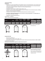
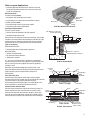
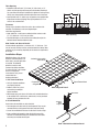
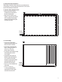
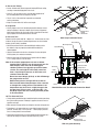
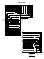
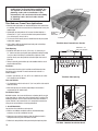
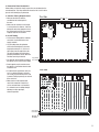
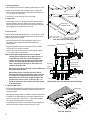
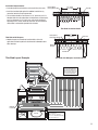
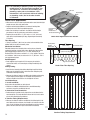
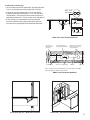
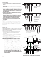
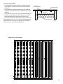
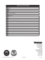
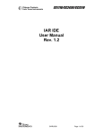
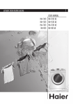
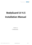
Heating PEX and Heating PEX-AL-PEX INSTALLATION MANUAL Contents WARNING ! General Handling & Storage3 General Installation Cautions3 Standards and Listings4 Slab-on-grade Applications5 Site Preparation5 Insulation Requirements5 Type of Insulation5 Post Concrete Pour5 Control Joints and Saw Cuts 5 Tube Spacing 6 Fasteners6 Slab Profile and General Details 6 Installation Steps6 Thin Slab over Frame Floor Applications 10 Tube Spacing10 Fasteners10 Thin Slab Profile 10 Installation Steps10 Insulation Requirements13 Thin Slab with Sleepers13 Thin Slab Layout Example 13 Under Floor Applications14 Tube Spacing14 Method of Installation14 Bend Supports14 Pulling Tubing14 Installation Steps14 Insulation Requirements16 Under Floor Layout Example 16 Warranty17 PO TA E OT FOR S N BLE U Note: Heating PEX and Heating PEX-AL-PEX are not approved or intended for use in potable water applications. Note: L ocal building or plumbing codes may require modifications to the information provided. You are required to consult the local building and plumbing codes prior to installation. If this information is not consistent with local building or plumbing codes, the local codes should be followed. You are required to thoroughly read all installation instructions and product safety information before beginning the installation of this product. FAILURE TO COMPLY WITH PROPER INSTALLATION INSTRUCTIONS COULD RESULT IN PROPERTY DAMAGE and/or PERSONAL INJURY. Local building or plumbing codes may require modifications to the information provided. You are required to consult the local building and plumbing codes prior to installation. If this information is not consistent with local building or plumbing codes, the local codes should be followed. Watts is not responsible for damages resulting from improper installation and/or maintenance. Contact Watts at 855.699.2887 with any questions concerning the installation, operation, or maintenance of Watts Heating PEX or Heating PEX-AL-PEX. ! CAUTION 1. Do not install within 6” (152.4 mm) horizontally or 12” (304.8 mm) vertically to a heat source such as: – recessed light fixtures – combustible flue vents – general heating appliances 2. Do not install directly to a heat source. A metallic adapter, minimum 18” (457.2 mm) in length, must be used between the heat source and tubing. 3. Do not support fixtures directly from the tubing, such as hose bibs or shut-off valves. 4. Protect the tubing via sleeves where it transitions through a concrete slab, concrete wall, or other framing material. 5. Not to be used with Insulated Barrier Heating PEX products. General Handling & Storage 1. If Heating PEX or Heating PEX-AL-PEX connections must be made in temperatures lower than 30.0°F (1.1ºC), caution must be taken to allow the tubing to form a proper seal against the barb. Apply the connection slowly to ensure the tubing material conforms to the barb. 2. Do not allow the fluid temperature to exceed: – 200.0°F (93.3ºC) at 80 psi (5.5 bar) for Heating PEX. – 200.0°F (93.3ºC) at 100 psi (6.9 bar) for Heating PEX-AL-PEX. 3. Do not allow the tubing to be exposed to sunlight, or direct UV exposure for more than 30 days maximum. If stored outside, tubing must remain covered by a UV resistant material. 4. Do not allow the tubing to come in contact with any of the following: – Petroleum based products • Pipe sealants. • Firewall sealants, except those rated for use with Heating PEX or Heating PEX-AL-PEX. • Kerosene. • Gasoline. • Fuel oils. • Cutting oils. • Asphalt. – Contaminated soils or building materials. 5. Do not use if the tubing has visible gouges, cuts, cracks, abrasions, signs of physical damage, or other defects. 6. Do not use in swimming pools or other systems that use high levels of chlorine. 7. Use bend supports when necessary (Heating PEX only). 8. Do not kink. If kinking occurs, use a repair coupling. 9. Do not expose tubing to rough terrain that may cause punctures, cuts, or other damage. 10. Do not use tubing to transfer natural gas or any other unapproved substance. 3 Standards and Listings Heating PEX: – Heating PEX is manufactured to ASTM International (ASTM F876 and F877) and to SDR9 dimensions. These standards include requirements and testing methods for materials, workmanship, dimensions, environmental stress cracking, sustained hydrostatic pressure strength, bend strength, and degree of cross-linking. Heating PEX meets or exceeds these standards. – Heating PEX is tested and listed by the NSF International to NSF-14 (rfh). – Heating PEX is tested and listed by Intertek to ASTM E84 (Standard Test Method for Surface Burning Characteristics of Building Materials) and meet the requirements of NFPA 90A. – Heating PEX is tested and listed to UL 263 (Fire Tests of Building Construction and Materials) by Intertek. – Heating PEX is listed by the International Code Council Evaluation Service (ICC) to Report #ESR-1155, and PMG-1008 which give compliance to IPC/IMC, and UPC/UMC. – Heating PEX is certified to CSA Standard B137.5. Expansion Rate: 1.1"/100'/10°F. Allow 1/8" slack for every foot of installed tubing. Description 1/2" Heating PEX 3/4" Heating PEX 1" Heating PEX R4" ID (OD) 0.485" (5/8") 0.681" (7/8") 0.875" (1-1/8") Minimum Bend Radius 5" 7" 9" R4" 6" R4" Fluid Capacity gal/100' 0.92 1.84 3.04 Min. Support Vertical Distance 48" 60" 60" Min. Support Horizontal Distance 32" 32" 32" R5" 8" R4" Temperature 73.4°F (23°C) 180°F (82.2°C) 200°F (93.3°C) Pressure 160 psi (1.10 MPa) 100 psi (0.69 MPa) 80 psi (0.55 MPa) The bend radius for Heating PEX may require some bends to be “light bulb” in shape. This method allows for tighter on center spacing without compromising the tubing. 10" R5" Heating PEX-AL-PEX: – Manufactured to ASTM F1281 – Tested and listed by the NSF R4" International (NSF-14 rfh).R5" R3" – Carries the UPC certification mark, as approved by the International Association of Plumbing and Mechanical Officials (IAPMO). Expansion Rate: 0.156”/100’/10°F. 8" to account for thermal expansion. 10" Note: No6"special considerations required Description 6" 1/2" Heating PEX-AL-PEX 3/4" Heating PEX-AL-PEX 1" Heating PEX-AL-PEX R4" R3" 6" 4 ID (OD) 0.500" (0.630") 0.806" (0.984") 1.032" (1.260") Minimum Bend 8" Radius 3.2" 5.5" 6.5" Fluid Capacity gal/100' 0.91 2.53 3.95 Min. Support Vertical Distance 10" 48" 60" 60" R5" 8" 10" Min. Support Horizontal Distance 32" 32" 32" Temperature 73.4°F (23°C) 180°F (82.2°C) 200°F (93.3°C) Pressure 200 psi (1.38 MPa) 125 psi (0.86 MPa) 100 psi (0.69 MPa) The bend radius for Heating PEX-AL-PEX is slightly tighter than Heating PEX but may still require some bends to be “light bulb” in shape. It is important, however, to ensure the minimum bend radius is not exceeded, as this will cause the tubing to kink. This method allows for tighter on center spacing without compromising the tubing. Slab-on-grade Applications Slab • A common application consisting of any material or mass that encapsulates the radiant tubing, such as concrete, sand, or soil. Can be on or below grade. Site Preparation A radiant slab should always: Heating PEX or • Be placed on well drained base rock material. Heating • Be placed above an ample amount of crushed rock or gravel. PEX-AL-PEX Base Rock A radiant slab should never: Rewire or Rebar • Be placed directly on top of clay or organic subsoil. • Be placed directly on top of solid bedrock. Slab-On-Grade Cross Section Insulation Requirements Two main areas to insulate: Slab: Minimum 2" (50.8 mm) covering above tubing • Vertically around the perimeter of the slab (required). 6" • Horizontally underneath the slab. 1" 1' Both aid in the slab’s response and efficiency. Of the two, vertical edge 3" 4 1/2" insulation is the most important for preventing heat loss directly to the 1" outside environment. Horizontal insulation helps decrease the slab’s required start up time by isolating the slab from the ground below. Type of Insulation Recommended insulation: • Extruded polystyrene insulation board or equivalent. Not recommended: Minimum 1" (25.4 mm) Extruded Polystyrene Insulation • “Beaded” insulation boards. • Foil-faced batt or board insulation. • “Bubble-type” insulation. A 1" (25.4 mm) insulation board (R-5 or better) is recommended. Slab Insulation Detail Thicker board may be used in cold, aggressive climates. Always check with an architect or structural engineer to ensure the appropriate insulation is used. Watts does not recommend bubble-type insulation under a slab Protective Joint Slab application. Most insulations of this type do not offer proper structural Sleeve support. Consult a structural engineer before using this or 12" min. (304.8 mm) Heating PEX or similar product. Heating Post Concrete Pour PEX-AL-PEX After the slab has been poured, interior walls and other support structures still have to be installed, typically secured directly to the slab. Take some preliminary precautions to protect the tubing Rewire during construction. Avoid wall locations, place tubing deeper in the Sub Grade or Rebar areas to be below any anchor that will penetrate the slab. Control Joints and Saw Cuts Slab Joint Concrete slabs will expand and contract due to thermal changes. To Rewire prevent damage to the slab, expansion joints are used to control Heating PEX or or Rebar expansion and contraction due to thermal changes. In some cases, Heating PEX-AL-PEX saw cuts are used to control where cracking occurs. Make sure the tubing is protected according to the requirements of the control joint. Expansion/Contro Pass Through Expansion/Control Pass Joints Through Pass Through Pass Under 3" min Sub Grade Pass Under Control Joint Options Do not exceed minimum bend radius of tubing 5 Tube Spacing • Residential slabs will use 6" (152.4 mm), 9" (228.6 mm), or 12" (304.8 mm) tube spacing with some perimeter banding. Banding is any area where the tubing is installed with a tighter on center spacing. Usually seen along exterior walls with higher than normal heat loss. 12 (304.8 mm) 9 • Spacing wider than 12" (304.8 mm) may produce unacceptable floor temperature variations (striping). Tube spacing wider than 12" on center is not recommended. (228.6 mm) 6 (152.4 mm) Fasteners Tubing can be attached to either the rewire, rebar or below slab insulation. The following can be used, depending on installation requirements: • Nylon CableTies—used to secure tubing to either rewire or rebar 12"-18" (304.8 mm - 425.2 mm) on center. Tube Spacing • Foam Board Staples can be used to secure tubing directly to the horizontal board insulation below the slab. Slab Profile and General Details In Slab-on-Grade applications, a minimum of 2"-3" (50.8 mm - 76.2 mm) of concrete covering must be maintained above the tubing. More coverage may be necessary depending on the structural requirements of the slab. Installation Steps Manifold locations, final concrete thickness and zoning details can affect how a concrete application is installed. The following guidelines cover the most common installation conditions. If a given situation is not covered here, or if unexpected circumstances arise, please contact Watts or a heating professional. 1. Pre-Pour Conditions • Verify all subgrade conditions are properly prepared. Insulation Layer and/or Vapor Barrier Typical Rewire Mesh Compacted Subgrade • Rewire or rebar are in place and installed according to design conditions. Slab Subgrade Detail Manifold Pair • With orange spray paint, locate all interior walls and other obstacles to be avoided, such as toilet areas, sewer drains, and any structural supports that may penetrate the slab. 2. Install Manifolds Locate where the manifolds are to be installed. • Drive two pieces of rebar vertically into the ground. They may be removed after the slab is poured and made ready for framing. Temporary Rebar Supports • Secure the manifolds with the use of cable ties or electrical tape. • Keep manifolds high enough to allow for the thickness of the concrete, the interior wall base plate and other structural items which may be installed after the pour. Slab - Manifold Installation Detail 6 3. Determine Zone Boundaries Before tubing is installed, visually inspect the area to determine the zone boundaries. This helps determine where the first circuit is to be placed, while identifying any obstacles. 4. Confirm Tubing Requirements • Measure the distance from the manifolds to the farthest point in the zone via right angles. Slab • Make sure the minimum circuit length is at least twice this distance. If not, the tubing will not be long enough to reach the farthest point of the zone and return. Manifold Location Supply Manifold Return Manifold 5. Install Tubing Slab • Pull one end of tubing off the unwinder and attach it to the first barb of one of the manifolds. • Install using a single serpentine pattern, keeping the tubing 6"-8" (152.4 mm - 203.2 mm) from the edge of the slab. • Pay attention to the footage marking on the tubing and cut at the correct length. • At expansion/control joints, the tubing may be passed under the area or must be sleeved with Armaflex® or PVC to pass through expansion/control joints (see Expansion Joints for details). • Use 1/2" (12.7 mm) tubing for the radiant floor. Manifold Location Supply Manifold Return Manifold • Use 3/4" (19.1 mm) or 1" (25.4 mm) Heating PEX or Heating PEX-AL-PEX for supply and return lines to the zone. 7 6. Secure the Tubing • Secure all bends and corners to prevent Heating PEX from curling, creating an unwanted high point in the circuit. • Leave 5' (1.52 m) slack on each circuit to allow adjustment of the manifold position from its temporary location. • Trim all “tails” of the cable ties to prevent any unwanted surface protrusions. • Keep all circuits within 10% of the same length. 8. Inspection • Visually inspect each circuit of tubing for possible damage caused during installation. If damage is found, repair it using an approved Watts repair kit. Wrap the repair with electrical tape (do not use duct tape) to protect the connection from the concrete. Rewire or Rebar Cable Tie 9. Pressure Test Slab Loop Installation Detail Pressure test the system with 50 - 100 psi (3.4 - 6.9 bar) water or air for 24 hours. Do not use water if exterior temperatures are near or below freezing (32.0°F (0.0ºC)) conditions. • Attach the pressure test kit to the manifold pair making certain the rubber o-rings are properly seated before threading the unions together. Heating PEX or Heating PEX-AL-PEX Air Test Gauge Mounting Bracket Supply Manifold Drain • Using the Schraeder valve for air or the water fill valves for liquid, fill the system (air or water, but not both). • Close the valve and fill. Pressure test the system with 50-100 psi (3.4 - 6.9 bar) water or air for 24 hours. Note: If the exterior temperatures are near or below freezing (32.0°F (0.0ºC )) use air to pressure test. If a fluid must be used, use a 50-50 water/glycol solution. Failure to use glycol may result in frozen circuits. The cool night air will usually cause less than a 10 psi drop in pressure as the water or air contracts from the cold. Barb Compression Ring Compression Nut Vent/Purge Heating PEX or Heating PEX-AL-PEX Return Manifold D o not test over 100 psi, (6.9 bar) as this will damage the gauge on the test kit. S ome minor pressure changes will occur due to the increased internal temperatures of the concrete as it begins the curing process. Fluctuations in air temperature may also cause a slight change in the test pressure. In most cases, a 10-15 psi (0.7 - 1.0 bar) drop in pressure over a twenty four hour period is not uncommon. Schrader Valve Balance Valve Drain Manifold Pressure Test Kit and Connection Detail 10. The Concrete Pour Slab • To help detect possible damage caused during the concrete pour, keep the system under pressure. If damage is apparent, locate the area in question and repair. • Minor pressure changes will occur during the concrete curing process. • Fluctuations in air temperature may cause slight changes in the test pressure. In most cases, a 10-15 psi (0.7 - 1.0 bar) drop in pressure over a 24 hour period is not uncommon. • Heated water should not be circulated through the finished pour for a minimum of 28 days, or until the concrete slab is fully cured. Subgrade Rewire or Rebar Heating PEX or Heating PEX-AL-PEX Slab-on-grade Cutaway 8 Slab Layout Examples Manifold Location Manifold Location 9 Note: L ocal building or plumbing codes may require modifications to the information provided. You are required to consult the local building and plumbing codes prior to installation. If this information is not consistent with local building or plumbing codes, the local codes should be followed. Floor Covering Thin Slab Thin Slab over Frame Floor Applications • Most thin slab applications are installed during the initial construction of a building, due to the increased structural requirements to carry the added weight. • Lightweight concrete products will increase the floor height by a minimum of 1.5" (38.1 mm) and the floor load anywhere between 12 to 18 lbs/sq.ft (5.44 k to 8.16 k). • The increase in load usually means a modification to the joist system and/or other supports. • Verify a floor’s ability to withstand these loads prior to installing a lightweight concrete product. Heating PEX or Heating PEX-AL-PEX Sub Floor Insulation Thin Slab Over Framed Cross Section Tube Spacing • Residential thin slabs will use 6" (152.4 mm), 9" (228.6 mm), or 12" (304.8 mm) tube spacing with some perimeter banding. Banding is any area where the tubing is installed with a tighter on center spacing. Usually seen along exterior walls with higher than normal heat loss. 12" max Mimimum 1-1/2" (38.1 mm) Thin Slab (304.8 mm) • Tubing is generally attached directly to the subfloor with the use of staples and/or NailTites. Fasteners Insulation The sub-material the thin slab is installed over will determine how the tubing can be attached. The most common sub-material is a wooden subfloor. • Staples—spaced every 18"-24" (457.2 mm - 609.6 mm) on center. Use a staple gun set to 100 psi. Thin Slab Tube Spacing Thin slab Profile • It is important to maintain at least 3/4" (19.1 mm) of thin slab material above the tubing. • More coverage may be necessary depending on the structural requirements of the slab/structure. Installation Steps Manifold locations, final concrete thickness, and zoning details are just a few items that can affect how a thin slab application is installed. The following guidelines cover the most common installation conditions. If a given situation is not covered here, or if unexpected circumstances arise, please contact Watts or a heating professional. 1. Install Manifolds Locate where the manifolds are to be placed. • With the use of Watts manifold brackets or manifold mounting enclosure, secure the manifolds to the wall. Manifold Thin Slab Heating PEX or Heating PEX-AL-PEX • Allowances may need to be made to allow the tubing to transfer through the wall base plate and into the thin slab. • Follow local code guidelines when penetrating framing base plates. Thin Slab - Manifold Installation Detail 10 2. Determine Zone Boundaries Before tubing is installed, visually inspect the area to determine the zone boundaries. This helps determine where the first circuit is to be placed, while identifying any obstacles. 3. Confirm Tubing Requirements Thin Slab • Measure the distance from the manifolds to the farthest point in the zone. 20 8 (6.3 m) • Make sure the minimum circuit length is at least twice this distance. If not, the tubing will not be long enough to reach the farthest point and still have enough length to return to the manifold. 4. Install Tubing • Pull one end of tubing off the unwinder and attach it to the first barb on the supply manifold. • Lay the tubing along the perimeter walls to the farthest point in the zone, keeping the tubing 6"-8" (152.4 mm 203.2 mm) from the edge of the slab. This will help protect the tubing from possible penetrations later on when the final floor covering is installed. • Pay attention to the footage marking on the tubing and cut at the correct length. 16 8 (5.1 m) Supply Manifold Return Manifold • Bend supports may be used to secure the tubing as it transitions from the thin slab to the wall. Thin Slab • In most thin slab applications, built-ins such as cabinets, showers, and walls are already in place before the thin slab is poured. Tubing is generally run around these “built-ins”. • Most structural code requirements restrict the amount of material that can be removed from a wall member. It is advised to run the tubing through doorways, or other openings, whenever possible. Supply Manifold Return Manifold Manifold Location 11 5. Securing Tubing • When installing a thin slab over a subfloor, standard staples are used. Thin Slab • Make sure the staple gun is set to 100 psi (6.9 bar) and does not come in contact with the tubing. Secure the tubing to the floor every 18"-24" (457.2 mm - 609.6 mm). • Try to keep all circuits within 10% of the same length. 6. Inspection • Visually inspect each circuit of tubing for possible damage caused during installation. If damage is found, repair it using an approved Watts repair kit. Wrap the repair with electrical tape (do not use duct tape) to protect the connection from the concrete. Heating PEX or Heating PEX-AL-PEX 18" to 24" Staple 7. Pressure Test Pressure test the system with 50-100 psi (3.4 - 6.9 bar) water or air for 24 hours. Do not use water if exterior temperatures are near or below freezing (32.0°F (0.0ºC)) conditions. • Attach the pressure test kit to the manifold pair making certain the rubber o-rings are properly seated before threading the unions together. • Using the Schraeder valve for air or the water fill valves for liquid, fill the system (air or water, but not both). Thin Slab Loop Installation Detail Supply Manifold Mounting Bracket Air Test Gauge Drain • Close the valve and fill. Pressure test the system with 50 - 100 psi (3.4 - 6.9 bar) water or air for 24 hours. Note: If the exterior temperatures are near or below freezing (32.0°F (0.0ºC)) use air to pressure test. If a fluid must be used, use a 50-50 water/glycol solution. Failure to use glycol may result in frozen circuits. The cool night air will usually cause less than a 10 psi drop in pressure as the water or air contracts from the cold. D o not test over 100 psi, (6.9 bat) as this will damage the gauge on the test kit. S ome minor pressure changes will occur due to the increased internal temperatures of the concrete as it begins the curing process. Fluctuations in air temperature may also cause a slight change in the test pressure. In most cases, a 10-15 psi (0.7 - 1.0 bar) drop in pressure over a twenty four hour period is not uncommon. Barb Compression Ring Vent/Purge Return Manifold Compression Nut Heating PEX or Heating PEX-AL-PEX Schrader Valve Balance Valve Drain Manifold Pressure Test Kit and Connection Detail 8. The Thin Slab Pour • To help detect possible damage caused during the concrete pour, keep the system under pressure. If damage is apparent, locate the area in question and repair. Finished Floor • Minor pressure changes will occur during the concrete curing process. • Fluctuations in air temperature may cause slight changes in the test pressure. In most cases, a 10-15 lb (0.7 - 1.0 bar) drop in pressure over a twenty four hour period is not uncommon. • Heated water should not be circulated through the finished pour for a minimum of 28 days, or until the concrete slab is fully cured. Thin Slab Subfloor Heating PEX or Heating PEX-AL-PEX Thin Slab Cutaway 12 Insulation Requirements Heating PEX or Heating PEX-AL-PEX • A standard paper faced insulation can be used in the joist cavity. 12" max (304.8 mm) Thin Slab • Install the insulation tight against the subfloor to minimize any convective losses that may be generated. • The insulation should be a minimum of 3-1/2" (88.9 mm), or R-13, fiberglass batt when the radiant floor is installed over a heated space, such as a basement. 5-1/2"(139.7 mm), or R-19, batt (or thicker, depending on the climate) should be used when the area below the radiant floor is unheated or exposed to the elements. Insulation Thin Slab Insulation Detail 8" Heating PEX or Heating PEX-AL-PEX Thin Slab with Sleepers • Wooden sleepers are sometimes installed within a thin slab application to allow for points of attachment for hardwood or other floor coverings. (203.2 mm) Thin Slab Wooden Sleeper Insulation Thin Slab Layout Example Thin Slab with Sleepers Insulation Detail Please note: In a thin slab application, typically the tubing will be run through doorways and other openings rather than directly through walls. G AS FI R EP LA C E WALK-IN CLOSET STORAGE LINEN Manifold Location SHOWER MASTER SUITE MASTER BATH SPA TUB 13 Note: L ocal building or plumbing codes may require modifications to the information provided. You are required to consult the local building and plumbing codes prior to installation. If this information is not consistent with local building or plumbing codes, the local codes should be followed. Sub Floor Heat Transfer Plate Under Floor Applications • Minimizes the structural load requirements often associated with light weight concrete (thin slab) construction. • Requires no floor height additions, or removal of existing floor coverings to install. Ideal for renovation projects. • Make sure the tubing is installed in accordance with the design parameters. If not, the system may not function as desired. • Requires the use of either a 1" (25.4 mm) or a 1-3/4" (44.4 mm) auger drill to install between joist bays, depending on how tubing is installed. Tube Spacing • Tubing is installed 8" (203.2 mm) on center, to the underside of the subfloor with the use of heat transfer plates. Method of Installation Extruded aluminum heat transfer plates are the primary fastening method of installing an under floor system. Watts offers heat transfer plates designed to be used with 1/2" (12.7 mm) Heating PEX or Heating PEX-AL-PEX and are available in 4' (1.2 m) lengths. The plates are installed 8" (203.2 mm) on center with a 2"-4" (50.8 mm - 101.6 mm) gap between plates. Bend Supports • Bend supports may be required if it is necessary to maintain a certain bend radius, or if connecting to a fitting immediately after a bend. Pulling Tubing • Install the heat transfer plates before beginning to pull the tubing. Make sure the end of the plate is de-burred after cutting the plate to fit before installing the tubing. • Measure the distance from the manifold to the farthest point moving in right angles to ensure proper circuit length is being used. This distance should be less than the circuit length for the zone. Installation Steps 1. Install manifolds. Locate where the manifolds are to be placed. • With the use of Watts manifold brackets or manifold mounting enclosure, secure the manifolds to the wall. 2. Determine Zone Boundaries • Before tubing is installed, visually inspect the area to determine the zone boundaries. This helps determine where the first circuit is to be placed, while identifying any obstacles. 3. Confirm Tubing Requirements • Measure the distance from the manifolds to the farthest point in the zone. Make sure the minimum circuit length is at least twice this distance. If not, the tubing will not be long enough to reach the farthest point of the zone and return (see slab section for illustration) Heating PEX or Heating PEX-AL-PEX Foil Faced Insulation Under Floor Application Cross Section Heating PEX or Heating PEX-AL-PEX 8" (203.2 mm) Heat Transfer Plate 2” (50.8 mm) air gap Foil Faced Insulation Under Floor Tube Spacing Supply Manifold Return Manifold Confirm Tubing Requirements 14 4. Drill joists (if necessary) • Drill in accordance to structural requirements. To help keep the holes in line, it may be helpful to first mark the joists with a chalk line. Ø 1-3/4" (44.4 mm) • If the supply and return sections of the circuit are to be installed through a common joist transition point, a 1-3/4" (44.4 mm) hole is required (option 1). If the supply and return sections are to be run in dedicated transition points, 1" (25.4 mm) holes can be used (option 2). • If using TJI joists, it may be possible to use the pre-fabricated knock-outs instead of having to drill transition points. Make sure the knock-outs are large enough for the tubing before proceeding. Option 1 Option 2 Under Floor Joist Penetration Detail Stay a min. of 8" (203.2 mm) from end of joist. 2" (50.8 mm) minimum spacing between penetrations. penetration zone max. bore size: 1/3 joist height Penetrations can not be closer than 2" (50.8 mm) to the top or bottom of the joist. center line joist height When crossing a joist at a perpendicular angle, it is recommended to follow BOCA 2305.3.2 guidelines for allowable joist penetrations. BOCA Joist Penetration Guideline Frame Floor Section - Manifold Installation Under Floor - Manifold Installation Detail 15 5. Install Tubing • Pull one end of the tubing from the unwinder and feed through the first joist. • Create a large loop with the tube and feed the free end through the adjacent joist. 1. Pull a loop of tubing in the first joist bay. • Make a small loop in each bay as you work towards the bay farthest from the manifold. Pull enough tubing to fill the last bay. If additional tubing is required, pull it from the loop in the previous bay. If too much was pulled, push it back into the previous bay. Care should be taken not to kink the tubing. • Run the end of the tubing back to the manifold. Drill a return hole 8" (203.2 mm) away from the first. • Place the tubing into the fasteners. Begin by attaching the run of tubing that is part of the return line going back to the manifold. This side of the loop is “fixed”. The other side is free to feed from the unwinder and previous bays in case extra tubing is required. 2. Continue to the next bay, pulling from the previous loop. Tubing will need to be pulled from the unwinder as well to keep enough of a loop in the first bay. • Always remember to place the tubing so bends have the largest radius possible. 3. Repeat for each subsequent bay Inspection After all the circuits are installed, take a few minutes to walk each circuit and visually inspect the tubing for possible damage caused during installation. If damage is found, repair it using an approved Watts repair kit. Pressure Test Pressure test the system with 50-100 psi (3.4 - 6.9 bar) water or air for 24 hours. Do not use water if exterior temperatures are near or below freezing (32.0°F (0.0ºC)) conditions. 4. Pull enough tubing to complete the last bay using the loop in the previous bay as a buffer for extra tubing. • Attach the pressure test kit to the manifold pair making certain the rubber o-rings are properly seated before threading the unions together. • Using the Schraeder valve for air or the water fill valves for liquid, fill the system (air or water, but not both). • Close the valve and fill. Pressure test the system with 50-100 psi (3.4 - 6.9 bar) water or air for 24 hours. Air Test Gauge Mounting Bracket Supply Manifold Note: If the exterior temperatures are near or below freezing (32.0°F (0.0ºC)) use air to pressure test. If a fluid must be used, use a 50-50 water/glycol solution. Failure to use glycol may result in frozen circuits. The cool night air will usually cause less than a 10 psi drop in pressure as the water or air contracts from the cold. D o not test over 100 psi (6.9 bar), as this will damage the gauge on the test kit. S ome minor pressure changes will occur due to the increased internal temperatures of the concrete as it begins the curing process. Fluctuations in air temperature may also cause a slight change in the test pressure. In most cases, a 10-15 psi (0.7 - 1.0 bar) drop in pressure over a twenty four hour period is not uncommon. Drain Barb Compression Ring Vent/Purge Return Manifold Compression Nut Heating PEX or Heating PEX-AL-PEX Schrader Valve Drain Balance Valve Manifold Pressure Test Kit and Connection Detail 16 Insulation Requirements • It is important to have a tight seal between the horizontal insulation and the joist itself. The tighter the joist cavity, the better the system will perform. • Foil insulation will ensure most of the heat and energy coming from the tubing is reflected upward towards the subfloor where it is evenly distributed.. Heating PEX or Heating PEX-AL-PEX Heat Transfer Plate 2” (50.8 mm) • A 2-4" (50.8 -101.6 mm) air gap is necessary between the tubing and insulation. This air gap helps increase the effective R-value of the insulation while optimizing the ability of the foil to reflect energy. • An R-value of at least 4 times higher than the floor is desire. For most interior conditions, an R-13, or a 3-1/2" (88.9 mm) batt should be used. When installing over an unheated area, exposed area or crawlspace, a minimum R-19 or 6" (152.4 mm) batt should be used. Foil Faced Insulation Under Floor Layout Example Supply Manifold Return Manifold 17 HEATING PEX and Heating PEX-AL-PEX HEATING, COOLING, and SNOW MELTING LIMITED WARRANTY From Watts 1. Watts warrants its Heating PEX cross-linked polyethylene tubing, Heating PEX-AL-PEX cross-linked polyethylene/ aluminum/cross linked polyethylene tubing, fittings, and factory manufactured manifolds to be free of defects in material and workmanship when used in hydronic heating, cooling, and snow melting systems. This limited warranty for tubing is valid for a period of twenty-five years from the date of manufacture. This limited warranty for Watts manufactured manifolds and fittings expires two years from the date of manufacture. All other Heating PEX and Heating PEX-AL-PEX accessories are warranted for one year after date of installation. 2. Watts obligation will be to repair or replace, at its discretion, any material proven to be defective when such material is covered under the following limited warranty. 3. In order to qualify for a labor allowance to repair or replace defective materials, you must contact Watts in advance and receive a written authorization for this allowance. Labor and freight expenses not authorized in writing in advance by Watts will not be compensated. 4. In the event of a system malfunction or leak caused by defective materials (and not by incorrect installation procedures or damage from handling procedures/jobsite conditions) repair materials and a reasonable labor allowance will be allowed. In the event of a leak occurring in a factory manifold, you may contact Watts for a free replacement manifold or any needed parts (freight prepaid). In the case of field-assembled manifolds, Watts warrants the quality and serviceability of the individual components sold by Watts that the contractor incorporates in that manifold, but Watts cannot warrant the complete manifold assembly or any field-assembled connections. That is the responsibility of the installing contractor. 5. To qualify for the above warranty you must do the following: a. Use good construction techniques to install our materials, as specified in our current design and installation guidelines and technical notes. This must include field pressure testing our materials before they are covered by concrete or otherwise made inaccessible. b. Install our materials according to all specific instructions furnished for your installation. c. Install Heating PEX or Heating PEX-AL-PEX in a system that will not operate at temperatures exceeding ratings as marked on the tubing. d. Product must be installed in compliance with all applicable plumbing, heating, cooling, and/or mechanical codes. 6. Evidence of tampering, mishandling, neglect, accidental damage, freeze damage, or unauthorized repairs that cause damage to Watts products will void any warranty coverage for these particular damages, although it will not void warranty coverage for unrelated items. Field repair joints and tubing-to-manifold connections are specifically excluded from the terms of this warranty. 7. Watts provides a complete radiant system offering so that it is possible to complete an installation with Watts products. However, it is possible that other manufacturers’ tubing and/or fittings may be installed in any given installation. Providing that the tubing and/or fittings are manufactured to the applicable ASTM standards, and have been certified by a recognized third-party testing agency, the Watts product in the given installation will continue to be covered under this warranty. In the event of a system malfunction or leak that has other tubing and/or fitting manufacturers’ components installed within the failed system, Watts will be responsible only for Watts products. Products manufactured by another company should be reported to that manufacturer for their warranty response. WATTS DISCLAIMS ANY WARRANTY NOT PROVIDED HEREIN, INCLUDING ANY IMPLIED WARRANTY OF MERCHANTABILITY OR FITNESS FOR A PARTICULAR PURPOSE. WATTS FURTHER DISCLAIMS ANY RESPONSIBILITY FOR SPECIAL, INDIRECT, SECONDARY, INCIDENTAL, OR CONSEQUENTIAL DAMAGES ARISING FROM OWNERSHIP OR USE OF THIS PRODUCT, INCLUDING INCONVENIENCE OR LOSS OF USE OR THE COST OF REPLACING OR REPAIRING OTHER PROPERTY WHICH IS DAMAGED IF THIS PRODUCT DOES NOT WORK PROPERLY. THERE ARE NO WARRANTIES WHICH EXTEND BEYOND THE FACE OF THIS DOCUMENT. NO AGENT OR REPRESENTATIVE OF Watts HAS ANY AUTHORITY TO EXTEND OR MODIFY THIS WARRANTY UNLESS SUCH EXTENSION OR MODIFICATION IS MADE IN WRITING BY A CORPORATE OFFICER. 8. Some states do not allow the exclusion or limitation of incidental or consequential damages and some states do not allow limitations on how long implied warranties may last. Therefore, the above limitations or exclusions may not apply to you. This warranty gives you specific legal rights and you may also have other rights which vary from state to state. Effective: July 1, 2011 This warranty applies to all products purchased after this date. Watts Regulator Company 815 Chestnut St. No. Andover, MA 01845 855-699-2887 (USA and Canada) 978-794-1848 (Fax) radiant.watts.com 18 Materials and Tools Checklist √ Measuring Tape Chalk Line Electrical Tape Marker Electric Drill 1-3/4" (44.5 mm) Hole Saw Safety Glasses Tubing Unwinder Tubing Cutter Bend Supports (for Heating PEX installation only) Manifold Box (optional) Heating PEX or Heating PEX-AL-PEX tubing Watts Copper Compression Manifold Kit (with correct number of circuit connections for tubing type installed) Heating PEX-AL-PEX Reamer (if installing Heating PEX-AL-PEX tubing) Railways (for slab-on-grade installations) Foam Board Stapler (for insulated slab-on-grade installations only) Foam Board Staples (for insulated slab-on-grade installations only) Foam Board Screw Clip Tool (for insulated slab-on-grade installations only) Foam Board Screw Clips (for insulated slab-on-grade installations only) Cable Ties (for slab-on-grade installations) Heat Transfer Plates (for under floor installations only) Under Floor Clips (for under floor suspended installations only) Watts Pressure Test Kit 815 Chestnut St. No. Andover, MA 01845 ph: 855.699.2887 fax: 978.794.1848 radiant.watts.com PO TA E OT FOR S N BLE U In Canada 5435 North Service Road Burlington, ON L7L-5H7 ph: 888.208.8927 905.332.4090 fax: 888.882.1979 905.332.7068 radiant.watts.com IOM-Heating-PEX-and-Heating PEX-AL-PEX 1136 EDP# 81015436 ©2011 Watts