1
CC1110/CC2430/CC2510
IAR IDE
User Manual
Rev. 1.2
SWRU038
Page 1 of 29
CC1110/CC2430/CC2510
Table of contents
1
2
3
3.1
INTRODUCTION .........................................................................................................................3
DEFINITIONS...............................................................................................................................3
INSTALLATION...........................................................................................................................4
CHIPCON CC1110/ CC2510 EXTENSIONS ........................................................................................4
3.1.1
3.1.2
3.2.1
3.2.2
Configuration Files............................................................................................................................................................... 4
Chipcon Library Files........................................................................................................................................................... 4
CHIPCON CC2430 EXTENSIONS .......................................................................................................5
Configuration Files............................................................................................................................................................... 5
Chipcon Library Files........................................................................................................................................................... 5
4
4.1
4.2
CC1110/ CC2510 LINKER FILE ................................................................................................6
XDATA RAM ...................................................................................................................................6
CODE ................................................................................................................................................7
4.2.1
Create HEX-file..................................................................................................................................................................... 7
5
5.1
5.2
CC2430 LINKER FILE ................................................................................................................8
XDATA RAM ...................................................................................................................................8
CODE ................................................................................................................................................9
5.2.1
5.2.2
5.2.3
Near code model ................................................................................................................................................................. 10
Banked code model ............................................................................................................................................................. 11
Create HEX-file................................................................................................................................................................... 12
6
7
7.1
7.2
8
8.1
8.2
9
9.1
9.2
DEBUGGER ................................................................................................................................14
ABSOLUTE PLACEMENT OF CODE AND VARIABLES.................................................15
CODE ..............................................................................................................................................15
VARIABLES .....................................................................................................................................15
CC2430 IEEE ADDRESS ...........................................................................................................16
WRITE AN ADDRESS........................................................................................................................16
READ AN ADDRESS .........................................................................................................................16
TUTORIAL ..................................................................................................................................18
CREATE A NEW PROJECT .................................................................................................................18
OPTIONS .........................................................................................................................................19
9.2.1
9.2.2
9.2.3
9.2.4
General Options, Code Model Near (Applies also to CCxx10) ......................................................................................... 20
General Options, Code Model Banked (Does not apply to CCxx10)................................................................................. 23
Linker .................................................................................................................................................................................. 24
Debugger............................................................................................................................................................................. 25
INCLUDE SOURCE FILES ..................................................................................................................26
COMPILE AND LINK ........................................................................................................................27
DEBUG ............................................................................................................................................28
3.2
9.3
9.4
9.5
10
DOCUMENT HISTORY............................................................................................................29
SWRU038
Page 2 of 29
CC1110/CC2430/CC2510
1
Introduction
This manual is written to clarify some aspects that have to be taken into consideration when
working with CC2430, CC2510 or CC1110 together with the IAR Workbench.
The CC2431 is in most of the aspects described in this manual equal to CC2430, and will not
be mentioned explicit. CC2431 is only delivered with a flash size of 128 kB. Every
configuration file available for CC2430 is also available for CC2431.
2
Definitions
CC2430-F32
CC2430-F64
CC2430-F128
CCxx10
CC2430 with 32KB FLASH
CC2430 with 64KB FLASH
CC2430 with 128KB FLASH
Refers to either CC2510 or the CC1110.
SWRU038
Page 3 of 29
CC1110/CC2430/CC2510
3
Installation
Install the IAR Embedded Workbench as described in the IAR User Manual.
3.1
Chipcon CC1110/ CC2510 Extensions
3.1.1
Configuration Files
C2510/CC1110 has 4 configuration files associated. For CC2510 these files are installed with
IAR Workbench, for CC1110 they can be downloaded from our web site. The configuration
files should be located according to Table 2.
File name
CCxx10.i51
CCxx10.ddf
lnk51ew_ccxx10.x
cl
ioCCxx10.h
Location
C:\Program Files\IAR Systems\Embedded
Workbench 4.05\8051\config\derivatives\chipcon
C:\Program Files\IAR Systems\Embedded
Workbench 4.05\8051\config\derivatives\chipcon
C:\Program Files\IAR Systems\Embedded
Workbench 4.05\8051\config
C:\Program Files\IAR Systems\Embedded
Workbench 4.05\8051\inc
Description
Setup some parts of an
IAR Project.
Describe each register
used in the debugger.
Set up the linker to reflect
CCxx10.
Header file for CCxx10.
Table 1: Configuration files
3.1.2
Chipcon Library Files
The files which are described here are part of the Chipcon library and can be downloaded
from www.chipcon.com.
In the IAR standard library, cexit will by default occupy one of the four hardware breakpoints.
To free this breakpoint include the file below in the project.
•
Chipcon_cexit.s51
Note:
Add $TOOLKIT_DIR$\SRC\LIB\ to Options -> Assembler -> Additional include directives.
SWRU038
Page 4 of 29
CC1110/CC2430/CC2510
3.2
Chipcon CC2430 Extensions
3.2.1 Configuration Files
CC2430 has five configuration files associated. These files are installed with IAR Workbench.
The configuration files are located according to Table 2.
File name
CC2430.i51
CC2430.ddf
lnk51ew_cc2430.xcl
lnk51ew_cc2430b.xcl
ioCC2430.h
Location
C:\Program Files\IAR Systems\Embedded
Workbench
4.05\8051\config\derivatives\chipcon
C:\Program Files\IAR Systems\Embedded
Workbench
4.05\8051\config\derivatives\chipcon
C:\Program Files\IAR Systems\Embedded
Workbench 4.05\8051\config
C:\Program Files\IAR Systems\Embedded
Workbench 4.05\8051\config
C:\Program Files\IAR Systems\Embedded
Workbench 4.05\8051\inc
Description
Setup some parts of an
IAR Project.
Describe each register
used in the debugger.
Set up the linker to reflect
CC2430.
Set up the linker to reflect
CC2430 with banked code
model.
Header file for CC2430.
Table 2: Configuration files
3.2.2 Chipcon Library Files
Some of the functions in the library included with IAR Workbench cannot be used with
CC2430.
The files which are described here are part of the Chipcon library and can be downloaded
from www.chipcon.com.
In the IAR standard library, cexit will by default occupy one of the four hardware breakpoints.
To free this breakpoint include the file below in the project.
•
Chipcon_cexit.s51
To use banked code model the following files have to be included in the project, they will
overwrite the files that are included by default in the IAR library.
•
•
Chipcon_cstartup.s51
Chipcon_banked_code_support.s51
Note:
Add $TOOLKIT_DIR$\SRC\LIB\ to Options -> Assembler -> Additional include directives.
SWRU038
Page 5 of 29
CC1110/CC2430/CC2510
4
CC1110/ CC2510 Linker File
There is one linker file for the CC2510 and one for CC1110.
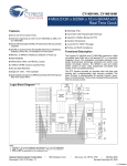
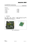
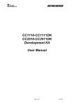
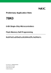
4.1 XData RAM
The linker files set up 4k of XData RAM. The range from 0xFDAA – 0xFEFF is used to store
register values during power mode (PM) 2 and 3. Hence, any data stored here before
entering PM 2/3 will be lost. If PM 2/3 is not used, the entire range from 0xF000 – 0xFEFF
can be used safely.
The XData RAM memory map in Figure 3 is reflected in the linker file.
0xFFFF
0xFF00
0xFEFF
0xFDAA
IData
Lose data in PM2/3
0xFDA9
Retain data in all PM
0xF000
Figure 1: XData RAM Memory
Figure 3 shows how XData is organized. To place variables in the memory space which is not
retained will have to be explicitly located in that memory segment (see chapter 7.1).
Note:
If your application is not using PM2/ PM3 you can change the linker file to use the full XData
memory. Change the line below in lnk51ew_cc1110.xcl or lnk51ew_cc2510.xcl:
From: -D_IXDATA_END=FDA9
To:
-D_IXDATA_END=FEFF
SWRU038
Page 6 of 29
CC1110/CC2430/CC2510
4.2 Code
The CCxx10 has 32 kB of code memory. This is reflected in the linker file the following way:
-D_CODE_START=0x0000
-D_CODE_END=0x7FFF
// 32KB code
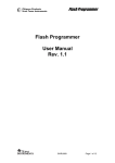
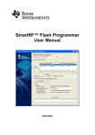
4.2.1 Create HEX-file
To generate a hex-file that can be downloaded to the CCxx10 by the Chipcon Flash
Programmer, setup the Project Options as shown in Figure 7.
Figure 2: HEX-file generation
SWRU038
Page 7 of 29
CC1110/CC2430/CC2510
5
CC2430 Linker File
CC2430 is delivered in three different versions CC2430-F32, CC2430-F64 and CC2430F128. There are two linker files for CC2430, lnk51ew_cc2430.xcl and lnk51ew_cc2430b.xcl.
They both reflect the physical aspects of CC2430. Lnk51ew_cc2430b.xcl is for CC2430-F128
and banked code model, lnk51ew_cc2430.xcl is for use with non-banked code, and can be
edited to reflect any chip model.
5.1 XData RAM
The linker file is by default set up to use 4k of XData RAM.
The XData RAM memory map in Figure 3 is reflected in the linker file.
Figure 3: XData RAM Memory
CC2430 has 8k XData RAM memory, but only 4k is preserved during Power Mode 2 and
Power Mode 3. Figure 3 shows how XData is organized. To place variables in the memory
space which is not retained will have to be explicitly located in that memory segment (see
chapter 7.1).
Note:
If your application is not using PM2/ PM3 you can change the linker file to use the full XData
memory. Change the line below in lnk51ew_cc2430[b].xcl:
From: -D_IXDATA_START=F000 // The internal xdata is 4k.
To:
-D_IXDATA_START=E000 // using low power RAM as normal RAM
SWRU038
Page 8 of 29
CC1110/CC2430/CC2510
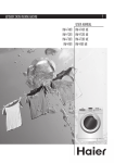
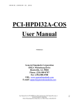
5.2 Code
When using Near Code Model, a maximum of 64k (bank 0 and 1, Figure 4) of code memory is
available (16 bits is used for address). When using Banked Code Model for CC2430-F128,
128k is available.
Lnk51ew_cc2430.xcl is set up to reflect CC2430-F128 and CC2430-F64 (both has 64 k flash
for non-banked code). To reflect CC2430-F32, edit the file as described below as well as in
the linker file. With use of this linker file, maximum code size is 64K.
lnk51ew_cc2430.xcl contains this fragment:
-D_CODE_END=0xFFFF
//-D_CODE_END=0x7FFF
// Last address for code, CC2430-F64 and CC2430-F128
// Last address for code, CC2430-F32
-D_NEAR_CODE_END=0xFFFF // Last address for near code, CC2430-F64
// and CC2430-F128
//-D_NEAR_CODE_END=0x7FFF // Last address for near code, CC2430-F32
For use of CC2430-F32, interchange the lines that are commented out.
Figure 4: Code banking
SWRU038
Page 9 of 29
CC1110/CC2430/CC2510
5.2.1
Near code model
For unbanked code, the address space is continuous and straight forward to use, see Figure
5. The “Physical View” is showing the address space as it is observed physically in the
CC2430-F64 and CC2430-F128. The “Linker View” is showing how the linker map addresses
to physical address, and “Debugger view” is showing where in the “Disassembly Window” the
code can be found.
Figure 5: Near Code Memory
SWRU038
Page 10 of 29
CC1110/CC2430/CC2510
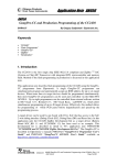
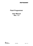
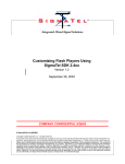
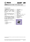
5.2.2
Banked code model
In Banked Code Model things get a bit trickier. Figure 6 shows the address space.
Note:
In “Linker View” the address space is not continuous.
To explicitly locate code in each bank, see chapter 7.1
Figure 6: Banked Code Memory
“Debugger View” is upside-down in the IAR Disassembly Window in relation to Figure 6.
“Bank 0*” in “Debugger View” is a copy of “Bank 0” and should not be taken into account.
SWRU038
Page 11 of 29
CC1110/CC2430/CC2510
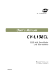
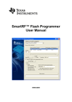
5.2.3
Create HEX-file
Because of the non-continuous address space when using banked code model, the HEX file
generated will not be usable with the Chipcon Flash Programmer. To map this address space
into one continuous address range, include the line below into the xcl-file or insert it in the IAR
IDE as shown in Figure 8. If this line is included the C-Spy debugger cannot be used.
-M(CODE)[(_CODEBANK_START+_FIRST_BANK_ADDR)(_CODEBANK_END+_FIRST_BANK_ADDR)]*_NR_OF_BANKS+10000=0x8000
To generate the file, setup the Project Options as shown in Figure 7.
Figure 7: HEX-file generation
SWRU038
Page 12 of 29
CC1110/CC2430/CC2510
Figure 8: Address translation for Banked Code
SWRU038
Page 13 of 29
CC1110/CC2430/CC2510
6
Debugger
The debugger is configured to match the specific chip with use of a definition file. For CC2430
the configuration file is named CC2430.ddf. For the CCxx10 the file is named CCxx10.ddf (xx
refers to either 11 or 25). To setup your project correctly, see chapter 9.
Some of the internal registers will disturb the state of the chip when they are read. These
registers will consequently not be shown with correct values in the register view window, see
Figure 9 . They will always be shown with value 0x00. (e.g. RFD, ADCH, ADCL, ENDO)
Figure 9: Register Window
SWRU038
Page 14 of 29
CC1110/CC2430/CC2510
7
Absolute Placement of Code and Variables
This chapter shows how to place code and variables at absolute addresses, and the chapter
is mainly intended for the CC2430. For an extended description please refer to the IAR user
manual.
7.1
Code
The linker file for CC2430-F128 has defined one code space for each bank. It is not required
to use these definitions for banked code model. The linker will distribute the code
automatically.
int f() @ "BANK1"{
return 1;
}
#pragma location="BANK1"
int g(){
return 2;
}
__near_func int main( void )
{
int a = g();
int b = f();
return 0;
}
Both f() and g() will be placed in code segment named BANK1. The main routine will be
placed in BANK 1 by default. To place main (or some other routines) in bank 0 use the
keyword __near_func, as indicated in the listing above.
The linker file for CC2430-F128 defines “BANK1”, “BANK2” and “BANK3”.
Note:
There is no banking for the CCxx10, as they only have 32 kB code memory size.
7.2
Variables
Absolute placement of variables is described below.
__no_init int myArray[128] @ "PM0_XDATA";
__no_init int myInteger @ 0xE000;
“PM0_XDATA” is defined in the linker file. This is the address space from 0xE000 to 0xEFFF.
It is necessary to explicitly define variables to be located in this area; if variables are “placed
by default” they will be located in address range 0xF000 to 0xFD57.
SWRU038
Page 15 of 29
CC1110/CC2430/CC2510
8
CC2430 IEEE address
When delivered in a kit each CC2430 has an IEEE address stored in code memory. The
segment is defined to be the last eight byte on the last flash page. Table 3 gives the address.
Chip
CC2430-F32
CC2430-F64
CC2430-F1281
CC2430-F128
Code model
Near
Near
Near
Banked
Physical
Address
0x07FF8
0x0FFF8
0x0FFF8
0x1FFF8
IAR Linker
Address
0x07FF8
0x0FFF8
0x0FFF8
0x3FFF8
Table 3: IEEE address space
The linker file defines a segment for the IEEE address, named “IEEE_ADDRESS_SPACE”.
8.1
Write an address
Use Chipcon Flash Programmer, available from www.chipcon.com, to write an IEEE address
to CC2430 or see the next section. Information about Chipcon Flash Programmer is available
in Chipcon Flash Programmer User Manual.
It is possible to write the IEEE address as part of a C program. “IEEE_ADDRESS_SPACE” is
defined in the linker file. To write an address to this segment, include the code below in the C
program (change the address). The IEEE address which the chip was delivered with is written
on the development card.
__root __code const unsigned char IEEE_ADDRESS[8] @ "IEEE_ADDRESS_SPACE" =
{0x00, 0x01, 0x02, 0x03, 0x04, 0x05, 0x06, 0x07};
If the chip already contains an address, this address will be overwritten by inclusion of this
example code.
8.2
Read an address
If the IEEE address is written to code as the example code in chapter 8.1 shows, it can easily
be read with use of the same variable.
If the address is stored in the chip, it can be read with use of the example code shown below.
If interrupt is enabled, remember to turn this off before calling the routine.
If the project is using code model near, set flash size to 64 for both CC2430-F64 and
CC2430-F128.
1
Not programmed when delivered
SWRU038
Page 16 of 29
CC1110/CC2430/CC2510
// #define CC2430_FLASH_SIZE 32
#define CC2430_FLASH_SIZE 64
// #define CC2430_FLASH_SIZE 128
#if (CC2430_FLASH_SIZE == 32)
#define IEEE_ADDRESS_ARRAY 0x7FF8
#elif (CC2430_FLASH_SIZE == 64) || (CC2430_FLASH_SIZE == 128)
#define IEEE_ADDRESS_ARRAY 0xFFF8
#endif
__near_func void getIEEEAddress(unsigned char *a){
#if ( CC2430_FLASH_SIZE == 128 )
unsigned char bank;
bank = MEMCTR;
// switch to bank 3
MEMCTR |= 0x30;
#endif
a[0] = *(unsigned char __code *)(IEEE_ADDRESS_ARRAY + 0);
a[1] = *(unsigned char __code *)(IEEE_ADDRESS_ARRAY + 1);
a[2] = *(unsigned char __code *)(IEEE_ADDRESS_ARRAY + 2);
a[3] = *(unsigned char __code *)(IEEE_ADDRESS_ARRAY + 3);
a[4] = *(unsigned char __code *)(IEEE_ADDRESS_ARRAY + 4);
a[5] = *(unsigned char __code *)(IEEE_ADDRESS_ARRAY + 5);
a[6] = *(unsigned char __code *)(IEEE_ADDRESS_ARRAY + 6);
a[7] = *(unsigned char __code *)(IEEE_ADDRESS_ARRAY + 7);
#if ( CC2430_FLASH_SIZE == 128 )
// restore old bank settings
MEMCTR = bank;
#endif
}
unsigned char addr[8];
int main( void )
{
getIEEEAddress(addr);
for(;;);
}
SWRU038
Page 17 of 29
CC1110/CC2430/CC2510
9
Tutorial
This chapter shows how to set up a new project for CC2430 in the IAR Workbench. A project
for CCxx10 can be set up in a similar fashion by replacing the CC2430-specific files with the
corresponding files for the chip in question.
The setup which is shown here use settings used for common projects. Both setup for project
using near code model and banked code model is presented.
The tutorial shows only screen shots from settings which need to be changed.
9.1 Create a new project
To quickly create a CC2430 application Chipcon recommends that the user begins by
creating a software project.
From the “Project” menu, choose “Create New Project…”.
Figure 10: Create New Project
Choose “Empty project” and press OK.
SWRU038
Page 18 of 29
CC1110/CC2430/CC2510
Figure 11: Choose Project Type
Figure 12: Save Project
Give the new project a name and press “Save”.
9.2 Options
To set up the project for use with CC2430 choose “Options” from the “Project” menu.
SWRU038
Page 19 of 29
CC1110/CC2430/CC2510
Chapter 9.2.1 describes all settings that need to be changed for CC2430 for code model near.
This also applies to CCxx10. Chapter 9.2.2 describes the settings that differ from code model
near to code model banked. This does not apply to CCxx10.
9.2.1
General Options, Code Model Near (Applies also to CCxx10)
Figure 13: Target, Code Model Near
In the “Derivative information” box select the CC2430.i51 file located in folder:
Embedded Workbench 4.05 \8051\config\derivatives\Chipcon.
Use
to select the file.
Set up rest of the settings on the “Target” settings as Figure 13 shows.
SWRU038
Page 20 of 29
CC1110/CC2430/CC2510
Use one data pointer. It’s important to set “DPTR select” to “Set using XOR/ AND” even if only
one DPTR is in use.
Figure 14: Data Pointer
SWRU038
Page 21 of 29
CC1110/CC2430/CC2510
Change XDATA stack size to 0x1FF.
Figure 15: Stack/ Heap settings
SWRU038
Page 22 of 29
CC1110/CC2430/CC2510
9.2.2
General Options, Code Model Banked (Does not apply to CCxx10)
Note:
Remember to include Chipcon_cstartup.s51 and Chipcon_banked_code_support.s51
(chapter 3.2.2 when using code model banked).
Figure 16: Target, Code Model Banked
The settings in Figure 17 are only available when Code Model Banked is active
Figure 17: Code Bank
SWRU038
Page 23 of 29
CC1110/CC2430/CC2510
9.2.3 Linker
Choose correct linker file, see chapter 4, as “Linker command file”.
Code
Model
Near
Banked
File
lnk51ew_cc2430.xcl
lnk51ew_cc2430b.xcl
Table 4: Linker files
Figure 18: Linker
SWRU038
Page 24 of 29
CC1110/CC2430/CC2510
9.2.4 Debugger
Use “Chipcon” as debugger, and check that the “Device Description file” is set to CC2430.ddf.
The ddf file is located in: Embedded Workbench 4.05 \8051\config\derivatives\Chipcon.
Figure 19: Debugger
SWRU038
Page 25 of 29
CC1110/CC2430/CC2510
9.3
Include source files
To create a new source file choose File -> New -> File.
Figure 20: Create new source file
Edit the file and save it into your project directory.
To add this, or another file to your project, choose Project -> Add files… Locate correct file
and click “Open”.
Figure 21: Add files to project
SWRU038
Page 26 of 29
CC1110/CC2430/CC2510
9.4 Compile and Link
To compile and link you project choose “Make” from the “Project” menu, or press F7.
Figure 22: Compile and Link
SWRU038
Page 27 of 29
CC1110/CC2430/CC2510
9.5 Debug
Start the debugger with “Debug” from the “Project” menu, or press CTRL+D.
Figure 23: Start debugger
Use of the debugger is described in the IAR user manual.
SWRU038
Page 28 of 29
CC1110/CC2430/CC2510
10
Document history
Revision
1.2
Date
2006-02-16
1.1
1.0
2006-01-18
2005-12-15
Description/Changes
Added CC2510 and CC1110. Changed
layout.
Removed link to configuration files on web
Initial release.
SWRU038
Page 29 of 29
IMPORTANT NOTICE
Texas Instruments Incorporated and its subsidiaries (TI) reserve the right to make corrections, modifications,
enhancements, improvements, and other changes to its products and services at any time and to discontinue
any product or service without notice. Customers should obtain the latest relevant information before placing
orders and should verify that such information is current and complete. All products are sold subject to TI’s terms
and conditions of sale supplied at the time of order acknowledgment.
TI warrants performance of its hardware products to the specifications applicable at the time of sale in
accordance with TI’s standard warranty. Testing and other quality control techniques are used to the extent TI
deems necessary to support this warranty. Except where mandated by government requirements, testing of all
parameters of each product is not necessarily performed.
TI assumes no liability for applications assistance or customer product design. Customers are responsible for
their products and applications using TI components. To minimize the risks associated with customer products
and applications, customers should provide adequate design and operating safeguards.
TI does not warrant or represent that any license, either express or implied, is granted under any TI patent right,
copyright, mask work right, or other TI intellectual property right relating to any combination, machine, or process
in which TI products or services are used. Information published by TI regarding third-party products or services
does not constitute a license from TI to use such products or services or a warranty or endorsement thereof.
Use of such information may require a license from a third party under the patents or other intellectual property
of the third party, or a license from TI under the patents or other intellectual property of TI.
Reproduction of information in TI data books or data sheets is permissible only if reproduction is without
alteration and is accompanied by all associated warranties, conditions, limitations, and notices. Reproduction
of this information with alteration is an unfair and deceptive business practice. TI is not responsible or liable for
such altered documentation.
Resale of TI products or services with statements different from or beyond the parameters stated by TI for that
product or service voids all express and any implied warranties for the associated TI product or service and
is an unfair and deceptive business practice. TI is not responsible or liable for any such statements.
Following are URLs where you can obtain information on other Texas Instruments products and application
solutions:
Products
Applications
Amplifiers
amplifier.ti.com
Audio
www.ti.com/audio
Data Converters
dataconverter.ti.com
Automotive
www.ti.com/automotive
DSP
dsp.ti.com
Broadband
www.ti.com/broadband
Interface
interface.ti.com
Digital Control
www.ti.com/digitalcontrol
Logic
logic.ti.com
Military
www.ti.com/military
Power Mgmt
power.ti.com
Optical Networking
www.ti.com/opticalnetwork
Microcontrollers
microcontroller.ti.com
Security
www.ti.com/security
Mailing Address:
Telephony
www.ti.com/telephony
Video & Imaging
www.ti.com/video
Wireless
www.ti.com/wireless
Texas Instruments
Post Office Box 655303 Dallas, Texas 75265
Copyright 2006, Texas Instruments Incorporated