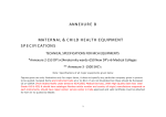
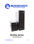
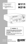
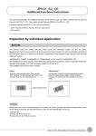
1
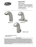
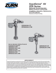
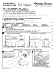
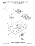
AquaSense®
ZTR Series
Automatic Sensor-Operated,
Battery-Powered Flushometer
Installation, Operation, Maintenance, and
Parts Manual
Models:
ZTR6200-ONE 1.1 gpf
ZTR6200EV 1.28 gpf
ZTR6200-WS1 1.6 gpf
Sensor-Operated, Battery-Powered Valve
ZTR6203-WS1 1.0 gpf
ZTR6203-EWS 0.5 gpf
ZTR6203-QRT 0.25 gpf
ZTR6203-ULF 0.125 gpf
LIMITED WARRANTY
All goods sold hereunder are warranted to be free from defects in material and factory workmanship for a period of three years from the date of purchase. Decorative
finishes warranted for one year. We will replace at no costs goods that prove defective provided we are notified in writing of such defect and the goods are returned to
us prepaid at Sanford, NC, with evidence that they have been properly maintained and used in accordance with instructions. We shall not be responsible for any labor
charges or any loss, injury or damages whatsoever, including incidental or consequential damages. The sole and exclusive remedy shall be limited to the replacement
of the defective goods. Before installation and use, the purchaser shall determine the suitability of the product for his intended use and the purchaser assumes all risk and
liability whatever in connection therewith. Where permitted by law, the implied warranty of merchantability is expressly excluded. If the products sold hereunder are
“consumer products,” the implied warranty of merchantability is limited to a period of three years and shall be limited solely to the replacement of the defective goods.
All weights stated in our catalogs and lists are approximate and are not guaranteed.
PRIOR TO INSTALLATION
Prior to installing the ZTR flushometer valve, install the items
listed below:
• Water Closet or Urinal Fixture
• Drain line
• Water supply line
IMPORTANT:
• All Plumbing is to be installed in accordance with applicable
codes and regulations.
• Water supply lines must be sized to provide an adequate
volume of water for each fixture.
• Flush all water lines prior to operation (See Step 2).
• Dirt and debris can cause flush valve to run continuously.
• Sensor units should not be located across from each other
or in close proximity to highly reflective surfaces.
• The ZTR valve operates optimally between 35 and 80 psi water pressure (running). The minimum pressure required for the valve
to work properly is determined by the fixture selected. Pleae consult fixture manufacturer for pressure requirements. To protect the
chrome finish, do not use toothed tools to install or service the flush valve.
*This Flush Valve should be used with a WaterSense labeled counterpart that has the same rated flush volume in order to ensure
that the complete system meets the requirements of the WaterSense specification for water efficiency and performance
*The ZTR6200-ONE (1.1 gpf) flush valve must only be paired with Zurn Z5615 Water Closet Fixture.
3.) Prepare Flush Valve for Assembly to Stop
Apply sealing
Prior to inserting the flush valve tailpiece (B) into stop valve (A),
be certain that the O-ring seal (C) is located in O-ring seal groove
at the end of the tailpiece and that the locking nut (D) and lockA
ing snap ring (E) are located as shown. Care should be taken
not to damage the O-ring when inserting the tailpiece into the
stop valve. If lubrication is needed, wetting the O-ring with water
will be sufficient. Tighten all connections with a non-toothed
wrench. See Figure 3
T
Figure
B
A
1.) Install stop valve assembly
Install stop valve assembly (A) using proper size supply escutcheon and sweat solder adapter kit if applicable. Thread
sealing compounds should be used only on this connection.
See Figure 1
Before the supply water is turned on, be sure all stop valves are
closed off tight. The stop valves can be opened and closed by
using the adjusting screw (S) located at the center of the stop
valve cap (T). Stop valve adjustments can only be made by using the adjusting screw (S). It is not necessary to remove the
stop valve cap (T) when making adjustments. If for any reason it becomes necessary to remove the stop valve cap (T),
be certain the water is shut off at the main supply valve. See
Figure 2
D
C
E
Figure
T
A
S
D
Figure 2
2.) Flush Water Supply
When all stops are connected to the water supply and water
pressure is available, the supply piping must be flushed to
remove dirt, metal chips, etc., from the system. Due to the
small passages and orifices, in the valve it is not possible to
flush the piping through the valve.
• Before the valve is installed, open each stop fully for a brief
time and catch the water in a two gallon or larger bucket. For
multiple installations, start with the stop valve closest to the
water supply and work toward the most remote valve.
• Once the lines are flushed, the valve can be installed.
FV541 Rev. G 6/20/2014
Page 2
B
Figure 4
4.) Assemble Valve to Stop
Insert the flush valve tailpiece (B) into the stop valve (A) and
hand tighten the lock nut (D) to the stop valve. Plumb the entire
unit. See Figure 4
D
Battery box
cover screw
AA Batteries
H
G
F
Figure 5
5.) Assemble Vacuum Breaker Tube
Determine the length of vacuum breaker tube (F) required to
join the flush valve and fixture spud. Cut the vacuum breaker
tube, if required, to this length. Assemble the vacuum breaker
tube assembly and spud nut assembly to the flush valve and
fixture spud. The rminimum rough-in height from the top of the
fixture to the centerline of the stop valve is 11.5”.
6.) Assemble Spud Nut and Vacuum Breaker Tube Nut
Hand tighten spud nut (G) and vacuum breaker tube nut (H) to
fixture and flush valve. Adjust the valve assembly for plumb.
Tighten fixture spud nut (G), vacuum breaker tube nut (H) and
lock nut (D) with a wrench. Tighten all connections with a nontoothed wrench. Turn on water supply.
Figure 7
• Loosen the battery box cover screw using the 3mm allen
wrench provided to access battery compartment.
• Load the 4 AA alkaline batteries following the battery orientation
guide on the outside of battery box cover. Note that the coil
springs always contact the flat (negative) end of the battery.
• Assemble o-ring to bottom of battery box cover.
• Align battery box cover arrow with sensor face.
• Insert cover to fit battery box guides (Opposite lens)
• Press battery box cover down-check to determine if fully
seated.
• While pressing, thighten center screw to positive stop.
• With target in front of sensor, unit should provide a red flash
within 60 seconds
• Reconnect the solenoid wire to the cap assembly. Note
that the flats of the two connectors must align.
• Secure the top assembly to the valve housing using the
original screws.
• Reinstall cover to the valve body from which it was removed.
8). Sensor Activation
• Normal activation of the valve will occur when the valve senses
an object (person). The LED will blink dimly four times about
a second apart. There will be a pause and then a double
blink. At this point, the valve has acquired a target.
• When the target leaves the view of the sensor, the valve will
actuate within 2-3 seconds.
• The target must remain in the sensing field for at least 6
seconds to charge the valve. This sensing cycle will prevent
the valve from flushing needlessly when someone walks by.
Solenoid
connecting
wire
Figure 6
7.) Installation of Batteries
• Using the 2mm allen wrench supplied with the valve in the
package containing the stop valve cover, remove the two 632 button head screws holding the top assembly in place.
(Be sure to place the screws somewhere safe so they do not
get lost.) See Figure 6
• Remove the top cover carefully and disconnect the solenoid
connecting wire. The cover and battery case can now be
accessed to install the AA cell batteries provided.
See Figure 7
• NOTE: The flush valve is designed for use on a water closet.
If the water closet is in a restroom, e.g. men’s restroom
with a limited number of urinals, the distance should be
extended in order to detect stand up users of the water
closet. Reference Section 11
• If special circumstances require the use of the manual
override button (MOB), press and hold the MOB for at least 2
seconds in order to assure a complete flush. (The ZTR MOB
delivers a manual, mechanical flush which is independent
of the sensor and battery voltage.)
FV541 Rev. G 6/20/014
Page 3
S
Figure 8
9.) Activate the Flush Valve
The ZTR6200EV flush valve comes preset for both flow volume
and sensing distance. Each valve is preset at the factory using
water to insure proper function before being packed for shipment.
To set the flush valve for proper operation, open the stop valve
completely by using the adjusting screw and flush several times.
Gradually adjust the stop valve, using the adjusting screw, so
that the rate of water flow into the fixture is not excessive, yet is
sufficient enough to adequately evacuate the waste. The stop
cap cover should be secured after final adjustments have been
made. See Figure 8.
10.) LOW VOLTAGE WARNINGS
• The red LED will flash every 10 seconds once certain low
battery levels are reached:
a. Low battery level - valve continues to flush. Change
batteries to avoid flush valve malfunction – reference
Section 13.
b. Insufficient solenoid power level – valve no longer
flushes – change batteries to reestablish flush valve
service.
c. Note: battery levels are selected to insure that every time
the flush valve operates, there is sufficient battery power
to close the flush valve.
• Reference Section 13 for instructions on replacing the
batteries.
11.) To Change the Sensor Activation Range
The detection / calibration range is the distance an object can
be away from the sensor in order to activate the valve. The
sensor is factory preset to 33" +/- 3.0". The valve does not have
to be disabled in any way to change the detection range.
Included with each valve is a Zurn “Magic Magnet” that is used
to initiate the auto-calibration mode. If necessary, calibration
is accomplished as follows:
1. Place a light color target the desired distance away from the
sensor.
2. Place the Zurn “Magic Magnet” on the front of the valve as
shown in Figure 10 and move slightly until the LED flashes.
3. The LED will begin to flash consecutively. Once the LED
has flashed 4 times, remove the magnet.
4. The LED will continue to flash as it is registering the new
target distance. After a total of 10 flashes, the new distance
is calibrated.
5. The new calibration should be tested using targets with
different color clothing to ensure calibration accuracy.
6. After sensor activation range calibratioin has been
performed, verify that the sensor does not detect stall doors
or other reflective surfaces.
FV541 Rev. G 6/20/2014
Page 4
12.) Courtesy Flush Function
The courtesy flush feature allows the user to set the time interval
between last flush and a bowl freshening/trap exchange flush.
The interval choices are (off), 24 hours, 48 hours and 72 hours.
The factory setting is off (0 hrs). Dip switches 2 and 3 control
this function. The settings are achieved by positioning 2 dip
switch toggles per figure 9. Please note that the remaining dip
switch toggles are preset at the factory. See Figure 9.
13.) Battery Replacement
• Using the 2mm allen wrench supplied with the valve, remove
the two 6-32 button head screws holding the top assembly
in place. (Be sure to place the screws somewhere safe so
they do not get lost.) See Figure 6
• Remove the top cover carefully and disconnect the solenoid
wire connector from the cap assembly connector. Always
pull on the connector and never the wires. The cover and
battery case can now be accessed to change the batteries.
See Figure 7
• NOTE: the sensor contained in the cover and battery case
has been specially matched to the valve body to achieve
the specific flow volume. The top cap assembly should be
returned to the specific valve after battery installation &
battery replacement.
• Loosen the battery box cover by unscrewing the cover screw
using the 3mm allen wrench provided to access the battery
compartment.
• Remove and discard the spent batteries.
• If the sensor will not activate the flush valve at the time of the
battery replacement, a sensor reset is required:
• Follow the instructions on the battery compartment
cover.
• Load the 4 AA alkaline batteries following the battery orientation
guide on the outside of battery box cover. Note that the coil
springs always contact the flat (negative) end of the battery.
• Assemble the o-ring to the bottom of the battery box cover.
• Align the battery box cover arrow with the sensor face.
• Insert the cover to fit the battery box guides (opposite lens).
• Press and hold battery cover against battery box –
determine if the battery cover is seated.
• Tighten cover screw to positive stop.
• With target in view of sensor, the sensor should flash
within 60 seconds.
• Insert the solenoid wire connector into the cap assembly.
Note that the flats of the two connectors must align.
• Secure the top assembly to the valve housing using the
original screws.
14.) Care and Cleaning Instructions
DO NOT use abrasive or chemical cleaners to clean flush
valves as they will dull the luster and attack the chrome or
special decorative finishes. Use only mild soap and water,
then wipe dry with a clean cloth or towel. While cleaning the
bathroom tile and floor, the flush valve and sensor should be
protected from splattering of water, cleaner, acids, and cleaning
fluids that can damage the sensor flush valve. DO NOT
PRESSURE WASH THE VALVE.
Courtesy Flush Settings (para 12)
Courtesy Flush
Dip Switch
Interval hours
2
3
0 – factory setting
On
On
24
On
Off
48
Off
On
72
Off
Off
Figure 9
Figure 10
TROUBLE SHOOTING GUIDE
Problem
Indicator
Red sensor flash every Sensor flashes (red) every 10 10 seconds
seconds
Sensor flashes (red) every 30 seconds
Valve Does Not Flush
No "10 second red sensor flash"
and
No "30 second red sensor flash"
and
Target detected but failed to flush upon target removal
Target detected but fails to flush upon target removal
No Target detection with target in range
Cause
Low battery voltage indication
Solution
Replace batteries – reference section 13.
Continuous target detection Identify and remove target from sensor field
Dirty, Scratched or Damaged Sensor Inspect & Clean Lens; if damaged, replace sensor
Lens
Battery level too low to activate full Replace batteries & reset sensor – reference flush – sensor shuts down valve to section 13.
avoid open flush
Dirty Lens
Sensor failure
Loose or damaged Solenoid Connection
Stuck Solenoid Plunger
Range too short
Dead batteries Sensor Failure
Clean lens Replace sensor & batteries
Re‐insert / repair solenoid to sensor connection
Remove solenoid – inspect, repair and clean plunger. Insure spring is vertical. Use scale removal material if needed.
Re‐calibrate range
Replace batteries
Replace sensor
Water Pressure either too high or too Adjust water pressure to recommended range of 20‐
80 psi
low
Clogged Orifice in Solenoid Diaphragm
Normal Target detection
Stuck Plunger
(With or without 10 second flash)
Valve Does Not Shut Off Water
Debris in Plunger
Remove Solenoid, inspect rubber diaphragm for clogged holes, clear holes, reassemble solenoid
Replace Solenoid Assembly
Remove Solenoid – inspect & repair & clean plunger. Insure spring is vertical. Use scale removal material if needed.
Piston Kit Clogged
Replace Piston Kit
Piston Kit Gasket Damaged
Bad Solenoid / Solenoid Connection Replace Solenoid Assembly
MOB damaged / leaking
Replace MOB
Sensor not flashing with "Target in View"
Dead Batteries
and
No 10 second or 30 second flashes
Electronics Failure
Replace batteries
Replaced Valve Cap Assembly
FV541 Rev. G 6/20/014
Page 5
®
ZTR6200EV Series Parts Breakdown
Parts Identification
1. Cover screw
2. Valve Cap/Sensor Assembly
3. Solenoid
4. Piston Cover Screws
5. Solenoid Kit
6. Flange O-rings
7. Piston Kit
8. Valve Housing
9. Manual Override Button
10. Filter
11. Valve Assembly
12. Vacuum Breaker
13. Vacuum Breaker Tube
14. Vacuum Breaker Tube Nut
15. Spud Nut
16. Spud Friction Washer
17. Spud Sleeve
18. Spud Escutcheon
19. Setscrew for Control Stop Cover
20. Vandal-Resistant Control Stop Cover
21. Stop Cap Bonnet
22. Stop Internals
23. Piston Seal
24. Stop Body
25. Sweat Solder Adapter
26. Supply Cover Tube
27. Setscrew for Cast Wall Escutcheon
28. Cast Wall Escutcheon
29. Hex Wrench
30. Top Valve Cap/Sensor Assembly
31. Battery Housing O-ring
32. Battery Cover
V a lv e an d C o m p o n e n ts
V a lv e Ho us in g, Ite ms 8 & 9
V a lv e Ca p, (1 .1 g pf ) , Ite m 2
V a lv e Ca p, (1 .2 8 gp f ), Item 2
V a lv e Ca p, (1 .6 g pf ) , Ite m 2
V a lv e Ca p, (1 .0 g pf ) , Ite m 2
V a lv e Ca p, (0 .5 g pf ) , Ite m 2
V a lv e Ca p, (0 .2 5 gp f ), Item 2
V a lv e Ca p, (0 .1 25 g pf ), Ite m 2
So len o id Re plac eme nt Kit, Ite m 5
Pis to n Kit (1 .1 /1 .2 8/1 .6 GPF), Item 7
Pis to n Kit (0 .5 /1 .0 GPF), Ite m 7
Pis to n Kit (0 .1 25 /0 .2 5 GPF), Ite m 7
Ma nu al Ov e rr ide Bu tto n A s s y , Ite m 9
Fla ng e O-Ring , Ite m 6
Fla ng e Sc re w , Ite m 4
Filter , ( 1.2 8 /1.6 gp f ) , Item 1 0
Filter , ( 1.0 /0 .5 g pf ), Ite m 10
Co v e r s c re w , Item 1
Pr o d u c t No .
PTR6 20 0- HSA
PTR6 20 0- L- 1.1
PTR6 20 0- L- 1.28
PTR6 20 0- L- 1.6
PTR6 20 0- L- 1.0
PTR6 20 0- L- 0.5
PTR6 20 0- L- 0.25
PTR6 20 0- L- 0.12 5
PTR6 20 0- M
PTR6 20 0- EC
PTR6 20 3- EU
PTR6 20 3- EU- UL F
PTR6 20 0- 24
PTR6 20 0- M-ring
PTR6 20 0- M-S
P60 0 0- FA
PTR6 20 3- FA
PTR6 20 0- L- S
Flu s h C o n n e c tio n s an d S p u d C o u p lin g Kits
P r o d u c t No .
Flu s h Co nn e c tio n a n d S pu d Co up ling ,
Ite ms 1 5- 1 8
V a c u um B re a ke r Rep a ir K it, Ite ms 11
V a c u um B re a ke r Tub e
V a c u um B re a ke r Tub e Nu t
P60 0 0 -H
P60 0 3 -H
P60 0 0 -B
P60 0 0 -A - CP
P60 0 0 -A A - CP
C o n t r o l S to p Re p a ir Kit a n d P a r t s
Co n tr ol S to p Re pa ir K it f or 1 ” a nd 3 /4” ,
Inc lu d e s Ite ms 1 4 -2 0
S e a l S e a t f o r 1” a n d 3 /4 ”, In c lu de s Ite m 2 3
S w ea t S olde r A d ap ter , In c lud e s Ite m 25
V a n d al re s is ta n t c o n tr ol s to p c ov e r
Ite ms 1 9- 2 0
S w ea t s o ld e r kit, Ite ms 2 5 -2 9
S w ea t s o ld e r kit, Ite ms 2 5 -2 9
P r o d u c t No .
P60 0 0 -C-S D- CP
P60 0 0 -D4 2
P60 0 0 -Y B A
P60 0 0 -V C
P60 0 0 -Y B Y C
P60 0 3 -Y B Y C
ZURN INDUSTRIES, LLC. ♦ COMMERCIAL BRASS OPERATION ♦ 5900 ELWIN BUCHANAN DRIVE ♦ SANFORD NC 27330
PHONE: 1-800-997-3876 ♦ FAX: 919-775-3541 ♦ WORLD WIDE WEB: WWW.ZURN.COM
IN CANADA: ZURN INDUSTRIES LLC ♦ 3544 NASHUA DRIVE ♦ MISSISSAUGA, ONTARIO L4V1L2 ♦ PHONE: 905-405-8272 FAX: 905-405-1292
FV541 Rev. G 6/20/2014
Page 6
6