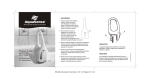
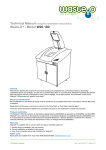
1
HydroACT 600 OPERATIONS MANUAL HydroACT 600 Analyzer, Controller, Transmitter Revised 07/18/11 JC PLEASE NOTE: In an attempt to reduce our company carbon footprint, this manual is normally supplied in an electronic format. If you require a printed copy, please ask your sales contact. Tel: 770-449-6233 Tel (US): 800-442-8722 Fax: 770-447-0889 Email: [email protected] Web: www.chemtrac.com Manual date 14th July 2011 Page 1 of 38 HydroACT 600 TABLE OF CONTENTS Page No. 1.0 1.1 SAFETY PRECAUTIONS Overview Specification 4 5 2.0 2.1 2.2 2.3 2.4 Installation Site selection Unpacking Mounting Electrical connections 6 2.4.1 2.4.2 2.4.3 2.4.4 2.4.5 2.4.6 3.0 Operation (Instrument) 3.0.1 3.1 3.2.2 10 13 General Information Device Codes Installed Hardware System Status Menu - Maintenance 3.2.1 9 Display, Buttons and Menu Menu - System Information 3.1.1 3.1.2 3.1.3 3.1.4 3.2 Power RS 485 Relays Probe(s) 4-20mA Inputs and Outputs 2.4.5.1 Inputs 2.4.5.2 Outputs Digital Inputs 7 8 Sensors 3.2.1.1 3.2.1.2 3.2.1.3 Outputs 3.2.2.1 3.2.2.2 14 Conversion Calibration Hold Calibrate Analogue Test 15 3.2.2.2.1 Analogue 3.2.2.2.2 Relays 3.2.3 3.2.4 3.2.5 3.3 Flush Now Factory Reset Master Reset Menu - Setup 3.3.1 3.3.2 3.3.3 3.3.4 16 Analyzer 3.3.1.1 Language 3.3.1.2 Date & Time 3.3.1.3 Display 3.3.1.4 User Interface 3.3.1.5 Buttons 3.3.1.6 Tag Details 3.3.1.7 Security 3.3.1.8 Upgrade... 3.3.1.9 Add Device Sensors Signals 3.3.3.1 Signal 1 / 2 3.3.3.2 Flush Delay Alarms & Thresholds 3.3.4.1 Alarms 17 18 19 3.3.4.1.1 Flow Alarm 3.3.4.1.2 Named Sensor 3.3.5 3.3.4.2 Thresholds Outputs 3.3.5.1 Map Analogue 3.3.5.1.1 Data 3.3.5.1.2 Control 20 3.3.5.2 Map Relay 3.3.5.2.1 Contact Manual date 14th July 2011 Page 2 of 38 HydroACT 600 3.3.5.2.1.1 3.3.5.2.1.2 3.3.5.2.1.3 3.3.5.2.1.4 3.3.5.2.1.5 3.3.5.2.1.6 Data Alarm Data Status System Alarm System Status Signal Control 21 22 23 3.3.5.2.2 Pulse Width 3.3.6 Controls 3.3.6.1 PID Controller 3.3.6.1.1 Manual 3.3.6.1.2 Auto 24 3.3.6.2 VSD Controller 29 3.3.6.2.1 Manual 3.3.6.2.2 Auto 3.3.7 3.4 3.3.6.3 Boost Options 3.3.7.1 Auto-Flush Menu - Logs 3.4.1 3.4.2 31 32 System Logs Data Logs 3.5 Alarm Information 4.0 Commissioning 5.0 5.1 Troubleshooting Guide Further help 33 APPENDICES A B C Certificates and approval statements Returns Procedure and ‘Free of Contamination Sheet’ Warranty Manual date 14th July 2011 34 35 37 Page 3 of 38 HydroACT 600 SAFETY PRECAUTIONS BEFORE ATTEMPTING TO UNPACK, SET UP, OR OPERATE THIS INSTRUMENT, PLEASE READ THIS ENTIRE MANUAL. MAKE CERTAIN THE UNIT IS DISCONNECTED FROM THE POWER SOURCE BEFORE ATTEMPTING TO SERVICE OR REMOVE ANY COMPONENT. MAKE CERTAIN THE UNIT IS DISCONNECTED FROM OTHER SOURCES OF FORCE OR PRESSURE (FOR EXAMPLE, PNEUMATIC OR HYDRAULIC), BEFORE ATTEMPTING TO SERVICE OR REMOVE ANY COMPONENT. FAILURE TO FOLLOW THESE PRECAUTIONS COULD RESULT IN PERSONAL INJURY AND DAMAGE TO THE EQUIPMENT. Manual date 14th July 2011 Page 4 of 38 HydroACT 600 1.0 Overview Thank you for purchasing a HydroACT 600 ANALYZER. The HydroACT 600 analyzer is a compact electronic communication and control system. It is designed for use with many different measuring probes. Any other use than the one described here compromises the safety of persons and the entire measuring system and is, therefore, not permitted. The manufacturer is not liable for damage caused by improper or non-designated use. Every analyzer is carefully checked before leaving the factory. If for any reason you are unhappy with your purchase, please contact the organization that you purchased the analyzer from, or Chemtrac, Inc. directly. Nearly all functions in this manual are common, certain exceptions have been noted. Ancillary items, such as probes, have their own additional manuals. Ensure you refer to them. 1.1 Specification Power: Fuse: Display: Outputs: Inputs: Comms: System Eventlogging: System Datalogging: Graphing: Weight: IP Rating: Box material: Lid material: Seals: Expansion slots: Micro SD slot: 100-240VAC (12VDC version available as an option), at approx. 8W (sensor no. dependant) 2A (100-240VAC), 2A (9-36VDC) LCD Backlit 128x64 graphical Up to 8 configurable contact relays, 380VAC, 8A / 125VDC, 8A OR up to 6 configurable solid state relays, 100-240VAC 3A OR up to 8 configurable solid state relays, 3-26VDC 3A Up to 6, 4-20mA outputs Up to 6 sensors / 4-20mA inputs 2 digital inputs (e.g. low flow switch) RS485 (used for communicating with some probes) 8000 events 8000 data points per channel before overwriting or continuing on MicroSD card Last 400 logged data points 1kg IP65 ABS Polycarbonate EPDM 4 1 Manual date 14th July 2011 Page 5 of 38 HydroACT 600 2.0 Installation As with all instrumentation the installation and commissioning of this instrument is crucial to its safe and accurate function. This instrument must be used only for its purpose as outlined in this manual and must be installed and commissioned in accordance with this manual and by trained and qualified personnel. 2.1 Site Selection Please choose a suitable location for the installation of the probe and the electronics. The choice of installation point on any site is a compromise and is best undertaken by experienced installation personnel. The following is a list of the factors that need to be taken into consideration. This list is not intended as a checklist neither is it implied that the list is complete. Ensure that the mounting allows access to all serviceable parts. Try to mount the electronics in a position where they are not habitually hosed down in a cleaning process. Consider the length of wiring runs when mounting the instrument. Try to keep the electronics away from substations or other large emi emitters. Consider whether the sample will be representative and well mixed. Consider sample return points. In a plastic run, with a low conductivity liquid sample, consider earthing the sample. 2.2 Unpacking Please have a copy of your order with you when you unpack your instrument. All orders are checked when they leave the factory. Please double check that you have all the parts that were ordered as soon as you open the box. If anything is missing, or damaged, please contact your sales outlet immediately. If the instrument needs to be returned for any reason please follow the instructions given in Appendix D of this manual. Manual date 14th July 2011 Page 6 of 38 HydroACT 600 2.3 Mounting Mounting the HydroACT 600. Please refer to the drawings below. The instrument electronics enclosure should be mounted away from sources of heat or direct sunlight. For mounting of optional parts, please refer to the manual supplied with that unit. Manual date 14th July 2011 Page 7 of 38 HydroACT 600 2.4 Electrical connections 2.4.1 Power Cable type and rating – 6.15mm overall diameter, 3 x 0.75mm2 conductors (24 strands), current rating 6A, 300V rated. Power connector and the fuse (F1, AC 2A). Manual date 14th July 2011 Page 8 of 38 HydroACT 600 2.4.2 RS 485 Cable type and rating – one pair, 22awg conductors, 120Ω impedance, 300V rated. Can be reserved for probe connection (SoliSense, OxySense or Conductivity/Salinity/Total dissolved solids). 2.4.3 Relays The unit has either up to 4 normally open (NO) relay contacts, or up to 4 solid state relays. Cable type and rating – 6.15mm overall diameter, 3 x 0.75mm2 conductors (24 strands), current rating 6A, 300V rated. 2.4.4 Probe(s) The probes connect via the connections, at the base of the HydroACT 600 board. Cable type and rating – 4mm overall diameter, 2 x 0.25mm2 conductors [HaloSense sensors (all types)], or multicore (co-axial cable together with multiple stranded cores) [for pH / ORP / fluorine sensors], or RS485 cable for SoliSense / OxySense. 2.4.5 4-20mA Inputs and Outputs Cable type and rating – 2 x 24awg conductors (7 strands), 300V rated, PVC outer sheath. 2.4.5.1 Inputs The AIP 4-20mA inputs are user selectable via jumpers. Consult Chemtrac, Inc. before attempting to change an input configuration. The powered input supplies +15Vdc @ 50mA max. NOTE: incorrect use of the input can cause failure to the board. 2.4.5.2 Outputs AOP. Maximum loop loading is 700Ω, at 14Vdc. 2.4.6 Digital Inputs 0/12Vdc. Can be used for low flow fail indication. Note: Please note that the use of expansion board within the HydroACT 600 means that some connectors can be difficult to access. This is a compromise to ensure that all possible functionality is available at a reasonable price inside a compact electronics unit. Manual date 14th July 2011 Page 9 of 38 HydroACT 600 3.0 Operation (Instrument) The HydroACT 600 is a complex set of electronics. 3.0.1 Display, Buttons(◙) and Menu The display is a backlit LCD colour display. The buttons are inductive and do not need to be pressed to activate. An extremely light touch or even hovering a finger over the button will activate it. Touching the button for an extended period will have the same effect as holding a key down on a PC keyboard. The up and down buttons on the right hand side of the display are always up and down. The remaining four buttons along the bottom are defined for each screen by the legend above the button on the display. The main display will look like this: By pressing the ‘Menu’ button you will be taken to the LOGON screen, were a User/Technician/Engineer code is entered (Note, buzzer is silent during code entry). Use the up or down◙ and left or right◙ to alter, and OK◙ enter. Press Cancel◙ to exit. If the right code is entered, the word User/Tech/Eng will appear in the top right of the display and you will be in the main menu where configuration of the instrument is performed. The default passwords are: User 1 Technician 2 Engineer 3 The access levels are shown by colour on the menu flow chart. Manual date 14th July 2011 Page 10 of 38 HydroACT 600 You need to LOG OFF, to swap between levels. The instrument will automatically log off after a timeout period, set in the menu at \Setup\Analyzer\Security\Timeout. By pressing the Calib button you will be taken to the calibration section, for the probe that was being displayed. Password entry may be required. If more than one sensor is fitted, then pressing the up or down arrow buttons will scroll around the sensors. By pressing the Alarms button (refer to section 3.5) you will be taken to a page that shows the current status of the alarms (password will be required). When an alarm is active (screen goes Red), the alarm screen will also have a button marked Ack. Pressing this button will acknowledge the alarm and silence the buzzer. The main menu is shown below, using Select◙ the menu option required. To return to the main menu at any time, simply press the button marked Exit, Cancel, No or Back on any of the screens shown. Manual date 14th July 2011 Page 11 of 38 HydroACT 600 Manual date 14th July 2011 Page 12 of 38 HydroACT 600 NOTE: the following statement is applicable to most of the following sections of Chapter 3 of this manual. Select◙ an option so it is highlighted . Abbreviations Select◙ Enter options using the Select button Use the vertical arrow buttons Use the horizontal arrow buttons OK◙ Press to accept Cancel◙ Press to cancel any changes Back◙ Press to return to the previous screen Exit◙ Press to leave that menu section without saving Next◙ Press to continue to the next screen in this menu section Finish◙ Press to save System information Maintenance Setup Logs Manual date 14th July 2011 Page 13 of 38 HydroACT 600 3.1 Menu - System Information 3.1.1 General Information Shows the Tag Name, Tag ID, Serial No., software Version and the date the software ‘Hex’ file was Created. Cancel◙ to exit. 3.1.2 Device Codes Shows the current setup of the analyzer. Exit◙ to exit. 3.1.3 Installed Hardware Shows hardware operating on the system (either base board or add-on cards). Exit◙ to exit. 3.1.4 System Status - Engineer Shows the Flash memory used (of 256k), the RAM used/total, HEAP (dynamic memory) used/maximum used/total, High water mark (highest address used), Stack (RAM allocated to task stacks) used/total. Cancel◙ to exit. Manual date 14th July 2011 Page 14 of 38 HydroACT 600 3.2 Menu - Maintenance 3.2.1 Sensors Select◙ Conversion / Calibration / Hold. 3.2.1.1 Conversion - Technician For setting/calibrating the input current loops. Select◙ Sensor. To calibrate the loop, following the on screen displays, inject 4mA, to continue press Next◙, then inject 20mA, to continue press Next◙. Results are displayed. Exit◙ or Finish◙. 3.2.1.2 Calibration Please refer to information manuals supplied with sensors. 3.2.1.3 Hold Each channel can have its output value placed on hold. This will maintain the output signal and alarm state in their current state for the selected period of time. The word Hold appears on the main display screen for the held channel, for the duration of the hold delay. Select◙ Sensor. OK◙ or Cancel◙. Select◙ Hold, adjust On/Off. OK◙ or Cancel◙. Select◙ Delay, adjust (30...3600sec.), only appears when Hold is On. OK◙ (to put channel on hold) or Cancel◙. Exit◙. Hold - can be cancelled by selecting Hold to Off. 3.2.2 Outputs Select◙ Calibrate Analogue / Test. 3.2.2.1 Calibrate Analogue then Select◙ Analogue channel, then Select◙ 4mA or 20mA. adjust the mA output. OK◙ (to temporarily save the change) or Cancel◙. Exit◙ or Finish◙. Manual date 14th July 2011 Page 15 of 38 HydroACT 600 3.2.2.2 Test Select◙ Analogue / Relays. 3.2.2.2.1 Analogue Select◙ Analogue channel. adjust the mA output in steps of 25%. Bar graph shows current output. OK◙ or Cancel◙ to finish test. Back◙. 3.2.2.2.2 Relays Select◙ Relay channel. to change the relay state. OK◙ or Cancel◙ to finish test. Back◙. 3.2.3 Flush Now – Optional Extra Select◙ operates the AutoFlush software, for sensor cleaning (all settings are in Setup\Options section of the menu). 3.2.4 Factory Reset - Technician Resets the unit. Press Next◙, then Yes◙ to Reset the unit, or No◙ to exit. NOTE: All data will be lost! 3.2.5 Master Reset - Engineer Resets the unit. Press Next◙, then Yes◙ to Reset the unit, or No◙ to exit. NOTE: All data and devices will be lost! Manual date 14th July 2011 Page 16 of 38 HydroACT 600 3.3 Menu - Setup 3.3.1 Analyzer Select◙ Language / Date & Time / Display / User Interface / Buttons / Tag Details / Security / Upgrade... / Add Device. 3.3.1.1 Language - Technician Select◙ Language. Then use the to adjust language. OK◙ or Cancel◙. Exit◙. 3.3.1.2 Date & Time - Technician Select◙ Date / Time / Weekday / Format. Then use the and to adjust. OK◙ or Cancel◙. Exit◙. Time in 24 hour entry Date in Format entry Format eg. D/M/Y 3.3.1.3 Display - Technician Select◙ Contrast / Backlight. Then use the and / or to adjust. OK◙ or Cancel◙. Exit◙. Backlight – time light remains active from last keypress. 0 sec. is backlight permanently ON. 3.3.1.4 User Interface - Technician Select◙ Buzzer / Display / Ticker. Then use the to adjust. OK◙ or Cancel◙. Exit◙. Buzzer – this is the keypad buzzer only. If set to Off, the keypad is silent, but the alarm buzzer still sounds. On / Off Display – Sensor / Single Parameter / Dual Parameter / Application. Sensor – shows all functions of the probe (eg. pH probe, pH as main display, temp. shown also) Single Parameter – main display shows only one sensor ( scroll to next sensor, eg pH only, scroll to temp.) Dual Parameter – main display shows two sensors on a horizontally split screen ( scroll to next sensor) Application – custom display (eg. AquaSense shows dosing information on the main display) Ticker – this is a line of information scrolling horizontally across the bottom of the main display. Off / Fast / Normal / Slow 3.3.1.5 Buttons - Technician Select◙ Button 1 / 2 / 3. Then use the to adjust. OK◙ or Cancel◙. Exit◙. Manual date 14th July 2011 Page 17 of 38 HydroACT 600 Allows main display shortcut buttons to be defined (eg. Button 1 – Cal. [calibrate], Button 2 – Alarms, Button 3 – Blank). The password must still be entered to access these menus. Options are: Blank Alarms Cal. Hold Senor Signal Ctrls Comms Info Status Boost Unused Alarm Information page Calibrate Hold Parameters Sensors Signals Controls Communication System Information System Status Boost Chlorine 3.3.1.6 Tag Details - Technician Select◙ Tag Name / Tag ID. Then use the and to adjust. OK◙ or Cancel◙. Exit◙. Allows customer to identify instruments two ways, by name or number (up to 16 characters). 3.3.1.7 Security Select◙ User / Technician / Engineer. Then use the and to adjust the password. OK◙ or Cancel◙. Exit◙. Default passwords are: User – 1 Technician – 2 Engineer – 3 Allows customer to set passwords by name or number (up to 8 characters). Select◙ Timeout. Then use the and to adjust the login time. OK◙ (to save the change) or Cancel◙. Exit◙. When this time is exceeded in either a menu or main screen, then you will be logged out. Note: if the HydroACT 600 is in a data entry screen, then the time out is inhibited. Manual date 14th July 2011 Page 18 of 38 HydroACT 600 If you lose you password, please contact PI, with the serial number of your instrument. We will supply a password that is only valid on the day you call. 3.3.1.8 Upgrade... - Technician The analyzer software may need to be upgraded. This is achieved by using a MicroSD card, in the front panel slot. Following the on-screen messages, the following sections can be upgraded: Resources this is the NODE (base) board software User this is the USER (keypad/display) board software I/O NODE board input/output GPRS Modem add-on board Ethernet add-on board Modbus add-on board Profibus add-on board 3.3.1.9 Add Device - Technician The device security code is unit serial number specific, and will be supplied with your equipment upgrade. Use the and to adjust. OK◙ or Cancel◙. Reset the power to the analyzer to finish the installation. 3.3.2 Sensors - Technician Please refer to separately supplied information. Screen background colours are: Grey offline Yellow warm-up Red alarm Green normal operation 3.3.3 Signals - Technician Select◙ Signal 1 / 2 / Flush Delay. 3.3.3.1 Signal 1 / 2 Select◙ Name / Enabled / Type / Alarm. Use the and to adjust. OK◙ or Cancel◙. Exit◙. Name – allows customer to identify input signals (eg. Flow). Name can changed (up to 16 characters). Enabled – Yes/No. No – off. Yes – on. Type – eg. the input signal comes from either a normally open or normally closed contact. Alarm – On/Off. In fault, On operates a Signal Alarm. 3.3.3.2 Flush Delay Select◙ Name / Restart / Delay / Duration. Use the and to adjust. OK◙ or Cancel◙. Exit◙. Name – allows customer to identify the signal that initiates a flush cleaning sequence. Name can changed (up to 16 characters). Restart – Yes/No. No – off. Yes – on. Delay – time between flush cycles. Duration – flush time. Manual date 14th July 2011 Page 19 of 38 HydroACT 600 3.3.4 Alarms & Thresholds - Technician Select◙ Alarms or Thresholds 3.3.4.1 Alarms - Technician Select◙ Sensor, eg. Flow or sensor name. 3.3.4.1.1 Flow Alarm Select◙ Flow Alarm. Then use the adjust On/Off. OK◙ or Cancel◙. Select◙ Signal 1 / 2, . These are the digital inputs 1 / 2. OK◙ or Cancel◙. Exit◙. Active alarms cause the sensor screen to turn red. This is a Sensor Alarm. 3.3.4.1.2 Named Sensor – eg Free Chlorine Select◙ Alarm 1 / 2. Then use the adjust On/Off. OK◙ or Cancel◙. Select◙ Set / Reset / Delay. Use the and to adjust. OK◙ or Cancel◙. Exit◙. Set – point at which alarm activates. Reset – point at which alarm deactivates. Delay – wait time before alarm activates. Active alarms cause the sensor screen to turn red. This is a Data Alarm. 3.3.4.2 Thresholds - Technician Select◙ Sensor. Select◙ Threshold 1 / 2. Then use the adjust On/Off. OK◙ or Cancel◙. Select◙ Set / Reset / Delay. Use the and to adjust. OK◙ or Cancel◙. Exit◙. Set – threshold activates. Reset – threshold deactivates. Delay – wait time before threshold activates. 3.3.5 Outputs - Technician Select◙ Map Analogue or Map Relay 3.3.5.1 Map Analogue - Technician Select◙ Analogue 1 / 2 / 3. OK◙ or Cancel◙. Select◙ Name / Enabled / Mode. Use the and to adjust. OK◙ or Cancel◙. Exit◙ or Next◙. Name – allows customer to identify output signals. Name can changed (up to 16 characters). Enabled – Yes/No. No – off. Yes – on. Mode – options Unused / Data / Control. Unused – off Manual date 14th July 2011 Page 20 of 38 HydroACT 600 Data – outputs the selected probe signal selected at Data (3.3.5.1.1) below Control – uses the output for PID or VSD control 3.3.5.1.1 Data Select◙ Sensor / Parameter. Use the and to adjust. OK◙ or Cancel◙. Back◙, Exit◙ or Next◙. Sensor – the signal source (eg. Chlorine Probe) Parameter – information only (not alterable) Select◙ Minimum / Maximum scaling range. Use the and to adjust the 4-20mA output range. OK◙ or Cancel◙. Back◙, Exit◙ or Next◙. Back◙, Exit◙ or Finish◙. 3.3.5.1.2 Control Select◙ Source PID or VSD controllers. Use the and to adjust. OK◙ or Cancel◙. Back◙, Exit◙ or Next◙. Back◙, Exit◙ or Finish◙. The output is now reserved for use by the selected controller. See relevant menu section. 3.3.5.2 Map Relay - Technician Select◙ Relay 1 / 2 / 3 / 4. Select◙ Name / Enabled / Mode. Use the and to adjust. OK◙ or Cancel◙. Exit◙ or Next◙. Name – allows customer to identify relay signals. Name can changed (up to 16 characters). Mode – options Unused / Contact / Pulse Width. Unused – off Contact – operates on signal set below (3.3.5.2.1) Pulse Width – uses the output for PID or VSD control 3.3.5.2.1 Contact – see flow diagram below Select◙ Source. Use the and to adjust (see options listed below). OK◙ or Cancel◙. Back◙, Exit◙ or Next◙. None Data Alarm Data Status System Alarm System Status Signal Control – off – set / reset on sensor level – thresholds / warm-up / calibrating / set to off-line – sensor disconnected / flow alarm – alarm acknowledged / unacknowledged – clock or digital in – AutoFlush Manual date 14th July 2011 Page 21 of 38 HydroACT 600 3.3.5.2.1.1 Data Alarm Select◙ Sensor / Parameter. Use the and to adjust. OK◙ or Cancel◙. Back◙, Exit◙ or Next◙. Sensor – the signal source (eg. Chlorine Probe) Parameter – information only (not alterable) Select◙ Fault Mask / Flow Mask / Alarm 1 Mask / Alarm 2 Mask. Use the to adjust. OK◙ or Cancel◙. Back◙, Exit◙ or Next◙. Fault Mask – operates the relay for a sensor fault * Flow Mask – operates the relay for a flow alarm * Alarm 1 Mask – relay operates at set/reset points* Alarm 2 Mask – relay operates at set/reset points* * has to be On in 3.3.4.1 Select◙ Action (Normally Open or Normally Closed relay contacts). OK◙ or Cancel◙. Back◙, Exit◙ or Next◙. Back◙, Exit◙ or Finish◙. Manual date 14th July 2011 Page 22 of 38 HydroACT 600 3.3.5.2.1.2 Data Status Select◙ Sensor / Parameter. Use the and to adjust. OK◙ or Cancel◙. Back◙, Exit◙ or Next◙. Sensor – the signal source (eg. Chlorine Probe) Parameter – information only (not alterable) Select◙ Warm-up Mask / On-line Mask / Off-line Mask / Threshold 1 Mask / Threshold 2 Mask. Use the to adjust. OK◙ or Cancel◙. Back◙, Exit◙ or Next◙. Warm-up Mask – operates the relay for sensor warming-up On-line Mask – operates the relay if the sensor is on-line Off-line Mask – operates the relay if the sensor is off-line Threshold 1 Mask – relay operates at set/reset points* Threshold 2 Mask – relay operates at set/reset points* * has to be On in 3.3.4.2 Select◙ Action (Normally Open or Normally Closed relay contacts). OK◙ or Cancel◙. Back◙, Exit◙ or Next◙. Back◙, Exit◙ or Finish◙. 3.3.5.2.1.3 System Alarm Select◙ All Alarms Mask / Data Alarms Mask / Sensor Fault Mask / Signal Alarm Mask / System Fault Mask. Use the to adjust. OK◙ or Cancel◙. Back◙, Exit◙ or Next◙. All Alarms Mask – operates the relay for any alarm Data Alarms Mask – operates the relay for any sensor alarm* Sensor Fault Mask – operates the relay for any sensor showing a fault Signal Alarm Mask – operates the relay for any signal alarm System Fault Mask – operates the relay for any system fault * has to be On in 3.3.4.1 Select◙ Action (Normally Open or Normally Closed relay contacts). OK◙ or Cancel◙. Back◙, Exit◙ or Next◙. Back◙, Exit◙ or Finish◙. 3.3.5.2.1.4 System Status Select◙ Normal Mask / Alarm Active Mask / Alarm Acknowledge Mask. Use the to adjust. OK◙ or Cancel◙. Back◙, Exit◙ or Next◙. Normal Mask – operates the relay for normal operation (no active alarms) Alarm Active Mask – operates the relay when any alarm is active (until the alarm is acknowledged) Alarm Acknowledge Mask – operates the relay when any alarm has been acknowledged (stays active until alarm is cleared) Manual date 14th July 2011 Page 23 of 38 HydroACT 600 Select◙ Action (Normally Open or Normally Closed relay contacts). OK◙ or Cancel◙. Back◙, Exit◙ or Next◙. Back◙, Exit◙ or Finish◙. 3.3.5.2.1.5 Signal Select◙ Source Signal 1 / 2 (these are the digital inputs) or Flush Delay. Use the to adjust. OK◙ or Cancel◙. Back◙, Exit◙ or Next◙. Select◙ Action (Normally Open or Normally Closed relay contacts). OK◙ or Cancel◙. Back◙, Exit◙ or Next◙. Back◙, Exit◙ or Finish◙. 3.3.5.2.1.6 Control Select◙ Source Auto-Flush 1 / 2. Use the to adjust. OK◙ or Cancel◙. Back◙, Exit◙ or Next◙. Select◙ Action (Normally Open or Normally Closed relay contacts). OK◙ or Cancel◙. Back◙, Exit◙ or Next◙. Back◙, Exit◙ or Finish◙. 3.3.5.2.2 Pulse Width Select◙ Source / Pulse Width / Dead Band. Use the and to adjust. OK◙ or Cancel◙. Exit◙ or Next◙. Source – select PID or VSD Controller. Pulse Width – the loop control time (during which the relay may be On / Off depending on the controller). Dead Band – if the PID controller On time for the loop is below this setpoint, do not operate the relay. Back◙, Exit◙ or Finish◙. 3.3.6 Controls – Technician Select◙ Controller (eg VSD / PID) / Boost. 3.3.6.1 PID Controller The HydroACT 300, HydroACT 600 and HydroACT 1200 controllers are capable of controlling processes such as chemical dosing with a pump and turning the pump on or off or up or down to maintain a setpoint. This is done using a PID control loop. PID stands for Proportional, Integral and Derivative. It is a mathematical manipulation of a measurement signal (e.g. the actual chlorine level) and the deviation of that signal from the setpoint (the setpoint being the desired outcome of the dosing pump control). The PID mathematical manipulation can be assigned to an analogue output or a relay where the time that the relay is on is controlled by the PID loop. This allows for any pump to be controlled by the PID loop. Please see below for a discussion of the mathematics involved in calculating PID output values. Manual date 14th July 2011 Page 24 of 38 HydroACT 600 Select◙ Name / Mode. Use the and to adjust. OK◙ or Cancel◙. Exit◙ or Next◙. Name – allows the user to identify the PID loop. Name can changed (upto 16 characters). Mode – Off / Manual / Auto. This either turns Off the PID control loop, puts it into Manual where the user specifies an output value, or puts it into Auto where the controller determines the appropriate output. 3.3.6.1.1 Manual Manual Output Select◙ Value. Use the and to adjust. OK◙ or Cancel◙. Back◙, Exit◙ or Next◙. Value – the output will be fixed to the % specified (eg if the user sets the output to 50%, then the analogue output would be fixed at 12mA, or the pulse width control relay would stop after half the loop time set at 3.3.5.2.2). Back◙, Exit◙ or Finish◙. 3.3.6.1.2 Auto Control Setup Select◙ Action / Setpoint / Maximum Output / Delay. Use the and to adjust. OK◙ or Cancel◙. Back◙, Exit◙ or Next◙. Action – Direct or Reverse. This sets the controller to increase the signal or decrease the controller signal either with (Direct) or against (Reverse) the measured parameter. So if the value of the measured parameter goes up with increased chemical addition then this needs to be set to 'Direct' (eg. Sodium Hypochlorite for Cl2). If the measured parameter goes down with increased chemical addition (e.g. adding acid makes pH go down), then this needs to be set to 'Reverse'. Maximum Output – whatever the PID wants to do this is the maximum that the output will go to. This is a useful 'common sense' limit to the controller and stops ridiculous over dosing if something goes wrong. Manual date 14th July 2011 Page 25 of 38 HydroACT 600 Delay – the control loop time e.g. for a setting of 0.5 sec, every half second the PID algorithm will run and the output will be updated. Lower values will be used for fast responding processes (small volumes of water), longer values should be used for slower responding processes. Note: AquaSense pool controllers use 60sec as a default value). It should be noted that 'noisy' or rapidly changing measurement parameters when combined with very low values of 'Delay' can result in unstable control. In these circumstances apply averaging to the measured parameter and increase the delay time. Setpoint – Static or Variable. Static – This is the value that the user requires in the process and can be manually entered at Setpoint Value (below). Variable – Setpoints are normally entered via the keys in the controller. In some circumstances the setpoint may vary based on external factors and this can be achieved by the setpoint tracking a 4-20mA input signal, Setpoint Source (see below). Process Variable Select◙ Sensor / Parameter. Use the and to adjust. OK◙ or Cancel◙. Back◙, Exit◙ or Next◙. Sensor – The process variable is the measurement parameter that the user is measuring in order to control the dosing. Usually the sensor and the parameter are the same thing. i.e. the chlorine sensor measures the chlorine parameter chlorine. Parameter – information only (not alterable). This is defined by the selected Sensor above. Setpoint Select◙ Value / Ramping. Use the and to adjust. OK◙ or Cancel◙. Back◙, Exit◙ or Next◙. Value – the control point value (this is the setpoint discussed above) Ramping – 0.01 to 1.00. Setting this value to zero turns it off. Ramping is for use during the startup of a process. PID control will often maintain a setpoint extremely well but during startup it struggles to get the process from zero to a stable setpoint. This is normally due to the process oscillating around the setpoint which in turn is due to the PID loop control making very large adjustments which then overshoot the setpoint and first one way and then the other and so on. It is possible to reduce this effect by either dosing manually until the measurement parameter is reading close to the setpoint and then turning on the control (this is often done in a swimming pool application). Alternatively the user can use the 'Ramping' function. The Ramping function effectively introduces the setpoint slowly. It does this by making small adjustments to the setpoint so that the setpoint itself changes until it is at the correct setpoint. It gradually changes the initial setpoint (set at the current reading) to the target setpoint (set in the menu). A setting of 1.00 will follow the target setpoint instantaneously (the Ramping has been turned off), while a setting of 0.01 will take a very long time. The exact amount of time depends on the PID delay setting. This has the effect of getting the PID to make a lot of small step changes rather than one very large stepchange. Setpoint Source Select◙ Sensor / Parameter / Ramping. Use the and to adjust. OK◙ or Cancel◙. Back◙, Exit◙ or Next◙. Sensor – the remote input signal to be tracked (eg. The 4-20mA input from a DCS). Parameter – information only (not alterable). This is defined by the selected Sensor above. Ramping – see Ramping in Setpoint section above. Manual date 14th July 2011 Page 26 of 38 HydroACT 600 PID Tuning Select◙ Proportional / Integral / Derivative. Use the and to adjust. OK◙ or Cancel◙. Back◙, Exit◙ or Next◙. Proportional – 0.00 to 10.00 gain. Zero is off. Proportional to the size of the current error. Integral – 0.00 to 10.00 gain. Zero is off. Proportional to the sum of all errors. Derivative – 0.00 to 10.00 gain. Zero is off. Proportional to the rate of change of error. PID control is a mathematical construct which can be understood and utilised mathematically or practically. Don't turn the controller on until you have read ALL of this section. Mathematics The output from the PID controller is simply the addition of the Proportional, Integral, and Derivative terms. This is then subject to the controls described above (such as Max Output). Output = Pout + Iout + Dout Where: Pout = Kp.e Iout = Iout + Ki.e.∆t Dout = Kd.∆e/∆t Kp - Proportional gain Ki - Integral gain Kd - Derivative gain e - Current error t - time Current error is the difference between the setpoint and the current measured value. Proportional control is used when the process water is recirculated (e.g. a Swimming Pool) Manual date 14th July 2011 Page 27 of 38 HydroACT 600 Integral Control is used when the process is a 'once through' process (i.e. not recirculated) or to correct a 'droop' following proportional control. Derivative control is rarely used. It can be used to correct overshoot when using Integral control but can introduce other problems. Proportional Gain is the simplest to understand and is simply that the further away from the setpoint the current measured parameter is the bigger the output signal. e.g. if the current value being measured for chlorine is a long way below the setpoint then the pump is turned up high. As the measured value gets close to the setpoint then the pump is turned down. For nearly all recirculating processes Proportional control IS ALL THAT IS NEEDED and Integral and Derivative control are not needed at all. If the proportional gain is set too high then the process can be unstable with the dosing overshooting the setpoint. If the proportional gain is set too low then the process is unresponsive and setpoint may never be achieved. In some processes the measured parameter is lost to the process e.g. chlorine from a pool, heat from a boiler etc. and sometimes in those circumstances the proportional control never quite catches up with the setpoint and users can see that although the process approaches the setpoint it rarely, if ever, gets to it. This is known as 'droop'. If this 'droop' is not a problem to the process then the recommendation would be to use only proportional control. If the user wants to eradicate the 'droop' then Integral gain can be applied to the signal to correct it. Integral Gain is the bit that adds up the amount of time that the measurement parameter has been below or above the setpoint. i.e. it records the time and degree that the measurement parameter has been above the setpoint and below the setpoint. It subtracts one from the other and then adds or subtracts an extra bit of signal. The Integral function is used instead of the Proportional term if the process is not recirculating. e.g. chlorine control on a water treatment plant. This term is often used when the primary control function is flow. i.e. flow proportional with residual trim. Alternatively the user can see that under a 'droop' condition (see above) then the Integral Gain function can increase the control signal to achieve the setpoint. Setting the Integral signal too low will have little or no effect while setting the Integral Gain too high will again cause overshoot and instability. If the Integral Gain is turned on then an additional option will appear. Manual date 14th July 2011 Page 28 of 38 HydroACT 600 Integral Windup Protection Select◙ Minimum / Maximum. Use the and to adjust. OK◙ or Cancel◙. Back◙, Exit◙ or Next◙. Minimum – -100.00 to 0.00. Zero is off (ie the Minimum is not longer held within the limits). Maximum – 0.00 to 100.00. Zero is off (ie the Maximum is not longer held within the limits). If Integral gain is set to a value greater than 0 then Integral Windup protection will be on the menu. If the Integral Gain is enabled and for some reason a positive or negative error occurs for a long time then the integral of that error will increase (or be 'wound up'). When whatever occurred is corrected it will then take a long time for the integral error to be 'unwound'. Take for example a swimming pool where the controller is calling for the pump to output at 50%. If the pump is broken then the controller will start to 'wind up' as there will be no chlorine going into the pool. This will result in a large error between the setpoint and the measured parameter. When the pump is repaired and back in service the integral gain will have the effect of overdosing until the integral gain has been 'unwound'. The Integral Windup Protection feature allows the user to set maximum and minimums in percentage of the setpoint. This protects against overshoot following large errors. Derivative. Warning. 99.9% of processes can be controlled without the use of this term. Only use this term if you are very confident of what you are doing. The Derivative term is used to reduce the overshoot caused by the Integral term. It does this by looking at the rate of change of the error and reducing it based on the derivative gain. The Derivative term is sensitive to noise and can have the effect of reducing the stability of the control. Practically Using PID practically is not nearly as hard as the above might suggest. Following this guide can help. 1) 2) 3) 4) 5) 6) 7) If your controller comes pre-set up with defaults (such as in an AquaSense) then use these before making any changes. (Defaults for AquaSense are 60s Delay time, with a Proportional Gain of 2 and both Integral Gain and Derivative Gain off) If your process is a flow through process (not recirculated) then start with just Integral. In nearly all cases Integral with windup protection is enough If you are using Integral control then put windup protection On. Then start very small and get bigger 0.1 perhaps to start. If your process is recirculating then start with proportional only...in nearly all cases proportional is enough. Keep the Delay time as long as possible depending on how quick your process is. The quicker the process then the smaller the delay time. The delay time is very unlikely to be longer than 300s or shorter than 10s. A setting of 1 for Proportional gain is 'directly proportional'. Increasing the number makes the control much quicker but could make it unstable. Go up or down slowly until you get the balance you want. Don't forget that going from 1 to 2 is a 100% change but from 3 to 4 is only a 25% change. Also from 1 to 0.5 is also a 100% change. If you have a recirculated process and you have setup your proportional and you do decide to use the integral function as well to eliminate droop, then put a windup protection on and start very small and get bigger slowly. If you think you need Derivative control you are probably wrong, please contact the factory for individual advice on your process. Back◙, Exit◙ or Finish◙. Manual date 14th July 2011 Page 29 of 38 HydroACT 600 3.3.6.2 VSD Controller The HydroACT 300, HydroACT 600 and HydroACT 1200 controllers are capable of controlling Variable Speed Drives. Select◙ Name / Mode / Delay. Use the and to adjust. OK◙ or Cancel◙. Exit◙ or Next◙. Name – allows customer to identify control loops. Name can changed (upto 16 characters). Mode – Off / Manual / Auto. This either turns Off the control loop, puts it into Manual where the user specifies an output value, or puts it into Auto where the controller determines the appropriate output. Delay – the control loop time e.g. for a setting of 0.5 sec, every half second the PID algorithm will run and the output will be updated. Lower values will be used for fast responding processes (small volumes of water), longer values should be used for slower responding processes. 3.3.6.2.1 Manual Manual Output Select◙ Value. Use the and to adjust. OK◙ or Cancel◙. Back◙, Exit◙ or Next◙. Value – the output will be fixed to the % specified (eg if the user sets the output to 50%, then the analogue output would be fixed at 12mA, or the pulse width control relay would stop after half the loop time set at 3.3.5.2.2). Back◙, Exit◙ or Finish◙. 3.3.6.2.2 Auto VSD Input Select◙ Sensor / Parameter. Use the and to adjust. OK◙ or Cancel◙. Back◙, Exit◙ or Next◙. Sensor – This is the measurement parameter that the user is measuring in order to control the VSD. Parameter – information only (not alterable). This is defined by the selected Sensor above. Manual date 14th July 2011 Page 30 of 38 HydroACT 600 Night Mode Select◙ Start / End / Output. Use the and to adjust. OK◙ or Cancel◙. Back◙, Exit◙ or Next◙. Start – The Night Mode start time. End – The Night Mode end time. Output – The fixed value to run the VSD at overnight. Example, start at 11:00pm, end at 06:00am, run the pumps at 85.00% of the normal frequency (ie 42.5Hz for a 50Hz electric motor). Day Mode Control Select◙ B1 Centre / B2 Deviation / B3 Deviation / Dead Band. Use the and to adjust. OK◙ or Cancel◙. Back◙, Exit◙ or Next◙. B1 Centre – The target value to be held by the system. B2 Deviation – The amount away from B1 Centre (+ or -) that causes a change of Band (ie into Band 2). B3 Deviation – The amount away from B1 Centre (+ or -) that causes a change of Band (ie into Band 3). Dead Band – The amount that must be “added” to get back into a lower band. Example, B1 Centre 1.70mg/l, B2 Deviation 0.50mg/l, B3 Deviation 1.00mg/l, Dead Band 0.10mg/l. The variable moves away from B1 Centre, until it reaches 1.20mg/l. At this, it drops into Band 2. The variable then increases but only returns to Band 1 at 1.30mg/l. Band 2 starts at either 1.20, or 2.20mg/l and ends at 1.30, or 2.10mg/l. Similarly, Band 3 starts at either 0.70, or 2.70mg/l and ends at 0.80, or 2.60mg/l. Day Mode Output Select◙ Band 1 / Band 2 / Band 3. Use the and to adjust. OK◙ or Cancel◙. Back◙, Exit◙ or Next◙. Band 1 – The fixed value to run the VSD at. Band 2 – The fixed value to run the VSD at. Band 3 – The fixed value to run the VSD at. Example, Band 1 at 44%, Band 2 at 46%, Band 3 at 48%. So as the variable moves away from B1 Centre, the pump speed increases. Back◙, Exit◙ or Finish◙. Manual date 14th July 2011 Page 31 of 38 HydroACT 600 3.3.6.3 Boost The Pool and Spa Controller unit allows for chlorine boost or shot dosing Select◙ Time / Delay / Output. Use the and to adjust. OK◙ or Cancel◙. Exit◙. Time – boost time Delay – time before next boost Output – pump output level during boost (eg 50%) Allows for chlorine shot dosing. The Boost will operate the pump at the Output % for the Time specified. The Boost will then be inoperable for the Delay time. 3.3.7 Options – Technician 3.3.7.1 Auto-Flush Select◙ Name / Control / Signal / Length / Hold Delay. Use the and to adjust. OK◙ or Cancel◙. Exit◙. Name – allows customer to identify signals. Name can changed (upto 16 characters). Control – On/Off. Signal – Flush Delay / Signal 1 / Signal 2. Flush Delay uses the Signal in 3.3.3. Signal 1 / 2 are the digital inputs. Length – flush length time. Hold Delay – hold the output signal / relays / etc. associated with the sensor being cleaned. Manual date 14th July 2011 Page 32 of 38 HydroACT 600 3.4 Menu – Logs 3.4.1 System Logs Select◙ System Logs. Use the to review the log. Cancel◙. 3.4.2 Data Logs Select◙ Data Logs. OK◙ or Cancel◙. Select◙ Sensor. OK◙ or Cancel◙. Select◙ Data or Graph (to view on screen), . Use the to review the Data log. OK◙ or Cancel◙. In Data, Select◙ Save to save a .csv file to a MicroSD card (if inserted). OK◙ or Cancel◙. Exit◙. 3.5 Alarm Information This page shows the state (On/Off) of the following alarms: Data Alarm Sensor Alarm Signal Alarm System Alarm An active (On) alarm causes the “spanner” light to flash, and a buzzer to sound (only in the main display, otherwise buzzer is silenced). Pressing the Ack. button on this page, acknowledges the alarm, silences the buzzer in the main display and changes the “spanner” light from flashing to solid. Manual date 14th July 2011 Page 33 of 38 HydroACT 600 4.0 Commissioning It is recommended that the HydroACT 600 is commissioned by a trained commissioning engineer. During the commissioning the engineer can train the operators in the correct operation of the HydroACT 600. The installation and commissioning should proceed in the following manner: 1) 2) 3) 4) 5) 5.0 Install the unit (refer to all of section 2.0). Check the instrument for damage. Make up the sensor(s) as required. Setup the instrument (refer to section 3.0) and any optional parts Calibrate instrument / sensor(s), then the system is fully commissioned. Troubleshooting Guide Symptom Possible cause Possible solution Check power is getting to the instrument No power No display or and check connections Open the unit and check the fuse LEDs Ribbon cable disconnected Turn off the power, then connect ribbon cable onto board LEDs light up, Display fault Return unit for repair no display Not selected in software Check assignment of output Jumpers in wrong Contact Chemtrac 4-20mA output not working position Relays not Not assigned in software Check assignment of relays working 5.1 Further help For more troubleshooting, please visit: www.chemtrac.com Manual date 14th July 2011 Page 34 of 38 HydroACT 600 Appendix A Certificates and approvals CE approval Declaration of conformity The product meets the legal requirements of the harmonized European standards. Chemtrac, Inc. confirms compliance with the standards by affixing the CE symbol. Waste electrical and electronic equipment (WEEE) Important information Disposal of old electrical & electronic equipment This symbol on the product or on its packaging indicates that this product shall not be treated as household waste. Instead, it shall be handed over to the applicable collection point for the recycling of electrical and electronic equipment. By insuring this product is disposed of correctly, you will help prevent potential negative consequences for the environment and human health, which could otherwise be caused by inappropriate waste handling of this product. The recycling of materials will help to conserve natural resources. For more detailed information about recycling of this product, please contact your local council or city office, your waste disposal service or the organization from which you purchased the product. Manual date 14th July 2011 Page 35 of 38 HydroACT 600 Appendix B Returns Procedure and ‘Free of Contamination Sheet’ If the analyzer has to be repaired, please return it cleaned to your local sale organization or Chemtrac, Inc. service center. Please enclose the completed Contaminant sheet (copy the Contaminants page, on the following page) with the packaging and shipping documents. No repair will be undertaken without a completed Contaminant sheet! Manual date 14th July 2011 Page 36 of 38 HydroACT 600 For more information about service and repair go to: www.chemtrac.com Contamination sheet Dear customer Because of legal requirements and for the safety of our employees, we need this “Contamination sheet” filled in (with your signature) before your instrument can be handled. Please put the completely filled in declaration with the instrument and the shipping documents. Add any safety data sheets (MSDS) and/or specific handling instructions if necessary. Type of instrument / sensor: __________________________________ Serial number: _______________________ Medium / concentration: __________________________________ Temperature: ______ pressure: _______ conductivity: ______ viscosity: _______ Cleaned with: __________________________________ Please mark the appropriate warnings. Radioactive ___ Explosive ___ Caustic ___ Poisonous ___ Harmful to health ___ Biologically hazardous ___ Inflammable ___ Safe ___ Company: Contact name: Address: Telephone/fax no: e-mail: Order no.: ______________________________ ______________________________ ______________________________ ______________________________ ______________________________ ______________________________ I hereby certify that the returned equipment has been cleaned and decontaminated according to good practices and is in compliance with all regulations. This equipment poses no health or safety risks due to contamination. ______________________________ Company stamp (if available) and legally binding signature Date _______________ Manual date 14th July 2011 Page 37 of 38 HydroACT 600 Appendix C Warranty Chemtrac, Inc. warrants its product to be free of defects in material and workmanship for a period of one (1) year from date of shipment to the original customer. Upon receipt of written notice from the customer, Chemtrac, Inc. shall repair or replace (at the discretion of Chemtrac, Inc.) the defective equipment or components. Chemtrac, Inc. assumes no responsibility for equipment damage or failure caused by: A. Improper installation, operation, or maintenance of the equipment. B. Abnormal wear and tear on moving parts caused by some processes. C. Acts of nature (i.e. lightning, flooding, etc.) This warranty represents the exclusive remedy of damage or failure of the equipment. Under no circumstances shall Chemtrac, Inc. be liable for any special, incidental, or consequential damage, such as loss of production, profits or product quality. The warranty cannot be guaranteed if the customer fails to service and maintain the equipment in accordance with Chemtrac, Inc. written instructions and policies, as stated in the Operations Manual. Manual date 14th July 2011 Page 38 of 38