1
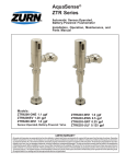
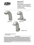
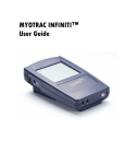
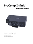
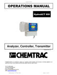
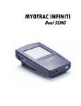
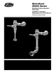
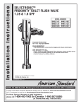
AquaSense® AV ZER Series Automatic Sensor-Operated, Battery-Powered Flushometer Installation, Operation, Maintenance, and Parts Manual Patented and Patents Pending ZER6000AV-CP ZER6000AV-CPM Sensor-Operated, Battery-Powered Closet/Urinal Systems ZER6000AV-CPM ZER6000AV-WS1-CPM ZER6001AV-CPM ZER6001AV-WS1-CPM ZER6003AV-CPM ZER6003AV-WS1-CPM LIMITED WARRANTY ZER6003AV-CP ZER6003AV-CPM All goods sold hereunder are warranted to be free from defects in material and factory workmanship for a period of three years from the date of purchase. Decorative finishes warranted for one year. We will replace at no costs goods that prove defective provided we are notified in writing of such defect and the goods are returned to us prepaid at Sanford, NC, with evidence that they have been properly maintained and used in accordance with instructions. We shall not be responsible for any labor charges or any loss, injury or damages whatsoever, including incidental or consequential damages. The sole and exclusive remedy shall be limited to the replacement of the defective goods. Before installation and use, the purchaser shall determine the suitability of the product for his intended use and the purchaser assumes all risk and liability whatever in connection therewith. Where permitted by law, the implied warranty of merchantability is expressly excluded. If the products sold hereunder are “consumer products,” the implied warranty of merchantability is limited to a period of three years and shall be limited solely to the replacement of the defective goods. All weights stated in our catalogs and lists are approximate and are not guaranteed. IMPORTANT: • ALL PLUMBING IS TO BE INSTALLED IN ACCORDANCE WITH APPLICABLE CODES AND REGULATIONS. • WATER SUPPLY LINES MUST BE SIZED TO PROVIDE AN ADEQUATE VOLUME OF WATER FOR EACH FIXTURE. • FLUSH ALL WATER LINES PRIOR TO OPERATION (See Step 9). • DIRT AND DEBRIS CAN CAUSE FLUSH VALVE TO RUN CONTINUOUSLY. PRIOR TO INSTALLATION Prior to installing the ZER Flushometer, install the items listed below: • Closet or urinal fixture • Drain line • Water supply line The ZER is designed to operate with 20 to 80 psi (138 to 552 kPa) of water pressure. THE MINIMUM PRESSURE REQUIRED TO THE VALVE IS DETERMINED BY THE TYPE OF FIXTURE SELECTED. Consult fixture manufacturer for pressure requirements. Protect the chrome or special finish of this flushometer. DO NOT USE TOOTHED TOOLS TO INSTALL OR SERVICE THE VALVE. A D A B 3 1 1.) Install stop valve assembly (A) using proper size supply escutcheon and sweat solder adapter kit if applicable. Thread sealing compounds should be used on male NPT threads only. 3.) Insert the flush valve tailpiece (B) into the stop valve (A) and hand tighten the lock nut (D) to the stop valve. Plumb the entire unit. B D C E F 2 2.) Prior to inserting the flush valve tailpiece (B) into stop valve, be certain that the O-ring seal (C) is located in O-ring seal groove at the end of the tailpiece and the locking nut (D) and locking snap ring (E) are located as shown. Care should be taken not to damage the O-ring when inserting the tailpiece into the stop valve. If lubrication is needed, wetting the O-ring with water will be sufficient. FV237 Rev. E 11/9/11 Page 2 4 4.) Determine the length of vacuum breaker tube (F) required to join the flush valve and fixture spud. Cut the vacuum breaker tube, if required, to this length. Assemble the vacuum breaker tube assembly and spud nut assembly to the flush valve and fixture spud. 5.) Hand tighten spud nut and vacuum breaker tube nut to fixture and flush valve. Adjust the valve assembly for plumb. Tighten fixture spud nut, vacuum breaker tube nut and lock nut with a wrench. Do not turn water on until batteries are inserted – see 6. 6.) ACTIVATION Using supplied battery compartment wrench, remove battery compartment from the E-Z Flush™ unit. Load batteries into compartment tray (note position of batteries in tray), and reinstall battery tray into the E-Z Flush unit. Secure tray with battery compartment wrench. The last three turns of the wrench will activate the E-Z Flush unit. The E-Z Flush System is now operational. Your E-Z Flush unit comes preset from the factory. If special circumstances require adjustment of the activation distance, see Appendix A – Adjusting Your E-Z Flush. The E-Z Flush unit has a 10-minute start-up sequence in which the Object Lock Sensor will flash the User-In-View yellow L.E.D. continuously as long as a user is in view. After the start-up sequence is completed and when the Object Lock Sensor has a user in view, the User-In-View yellow L.E.D. will flash only 3 times after a 5-second delay. This delay prevents needless flushes when someone walks by. Sensor units should not be located across from each other or in close proximity to highly reflective surfaces. 6 7.) VISUAL INDICATOR GUIDE USER-IN-VIEW L.E.D. Yellow light flashes 3 times – after 5-second delay – when a user is in view. The yellow light flashes constantly when a user is in view during the 10-minute start-up sequence. OBJECT LOCK SENSOR BATTERY L.E.D. Red light flashes indicating it is time to replace batteries with 4 new “C” batteries. COURTESY MANUAL FLUSH BUTTON Allows manual activation of flush when needed. 8.) ADJUSTING YOUR E-Z FLUSH STEP A Use battery compartment STEP B Pull cover off by rotating battery STEP C Sensor Adjustor Tool comes in wrench to remove battery compartment side forward and out. tray. a built-in storage pocket. Replace after use. FV237 Rev. E 11/9/11 Page 3 T 10 9a Before the supply water is turned on, be sure all stop valves to the flush valves are closed off tight. The stop valves can be opened and closed by using the adjusting screw located at the center of the stop valve cap (T) , behind the adjusting screw cover if already installed. Stop valve adjustments can only be made by using the adjusting screw. It is not necessary to remove the stop valve cap when making adjustments. If for any reason it becomes necessary to remove the stop valve cap, be certain the water is shut off at the main supply valve. 10.) The ZER flush valves are preset for fixture volume as marked on the valve cartons. The valve does not require regulation for variation in water pressure within its operating range. To set the flush valve for proper operation, gradually adjust the stop valve open, using the adjusting screw, while actuating the valve until the rate of water flow into the fixture is not excessive, yet is sufficient to adequately evacuate the waste. The final setting for urinals should be such that the fixture will not overflow when the valve is actuated in succession. The stop cap screw cover should be replaced after final adjustments have been made. O P APPENDIX A Q New RetroFlush Diaphragm Kit Working Parts 9b 9.) When all flush valves are connected to the fixtures and water pressure is available, it is recommended that the supply piping be flushed to remove dirt, pipe chips, etc., from system. Use the following procedure to flush out the supply piping: A. Remove the main valve body cover .(O) B. Remove the working parts from the flush valve (P) and (Q) (shown in 9b). C. Replace the plastic cover (P) and main body cover (O) without reinstalling the working parts. D. Open the stop valve by using the stop adjusting screw and flush out all debris from pipe and connections. E. Shut stop, open cover, reinstall the working parts, replace both covers and tighten. This procedure should also be repeated when the system is drained for seasonal use, as occurs in athletic fields, recreation parks, etc. FV237 Rev. E 11/9/11 Page 4 TO CHANGE ACTIVATION DISTANCE FOR THE OBJECT LOCK SENSOR 1. Remove battery compartment tray as shown in Step 6. 2. Remove cover and sensor adjustor tool as shown in Step 6. 3. Replace battery compartment in E-Z Flush to activate unit. 4. Press sensor range reset button (the yellow L.E.D. will flash continuously when it has an object in view for the 10-minute reset period). 5. Stand at desired activation distance. 6. Use sensor adjustor tool and turn Distance Adjustment Screw all the way down and then turn slowly up until yellow L.E.D. begins to flash. 7. Ensure Object Lock Sensor is not detecting stall door or wall by closing door, stepping out of sensor path and making sure yellow L.E.D. is not flashing. If sensor locks onto door or wall, unit will not flush properly. Shorten activation distance. 8. Remove battery compartment, replace sensor adjustor tool and cover. Replace battery compartment tray to reactivate E-Z Flush unit. 9. After 10-minute start-up sequence, the yellow L.E.D. will flash only 3 times when a user is in view (after a 5-second delay). WIRING DIAGRAM Delay Flush = User must leave the sensor range for 3 seconds before a flush is generated. 24 Hour Flush = Unit will automatically flush 24 hours after the last use. TROUBLE SHOOTING GUIDE PROBLEM CAUSE SOLUTION Yellow L.E.D. light flashes 3 times when there are no users. Front of Object Lock Sensor is covered or Object Lock Sensor is set too far out, registering the opposite wall or door as a user. Remove item covering sensor or adjust Object Lock Sensor activation distance. (See Appendix B – Adjusting the E-Z Flush.) Yellow L.E.D. light flashes continuously when Object Lock Sensor is activated by a user. E-Z Flush unit is in 10-minute start-up mode (when first activated), or Sensor Range Reset Button has been depressed. Yellow L.E.D. light will flash only 3 times,acknowledging a user is in view after the 10-minute start-up mode. Red L.E.D. light flashes. Batteries need replacing. Replace batteries. Not enough water to fixture or too much water to fixture. Diaphragm damaged or valve control stop improperly adjusted. Replace diaphragm and/or adjust valve control stop. Valve will not operate. Object Lock Sensor range set too close to E-Z Flush, batteries are dead, or water supply is turned off. Adjust Object Lock Sensor, replace batteries, or turn water on. If the E-Z Flush does not begin to function, call Customer Service at 1-800-997-3876. Valve does not shut off. Dirt or debris preventing diaphragm from functioning properly. Remove dirt or debris, check by-pass hole in diaphragm. Valve does not flush even after Object Lock Sensor has been adjusted. Batteries are dead. Replace batteries. If the E-Z Flush does not begin to function, call Customer Service at 1-800-997-3876. FV237 Rev. E 11/9/11 Page 5 AquaVantage® Exposed E-Z Flush Repair Kits Part Identification 1. Seal 2. Collar Gasket 3. Sensor Module 4. Manual Overide Push Button 5. Replacement Sensor Lens 6. Chrome Plastic Cover 7. Chrome Metal Cover 8. Battery Drawer 9. O-Ring 10. Allen Wrench 11. Handle Nut Wrench 12. Valve Body Cover 13. Plastic Cover 14. Trip Mechanism 15. Diaphragm Repair Kit 16. Valve Body 17. Vacuum Breaker Duckbill 18. Vacuum Breaker Tube 19. Vacuum Breaker Tube Nut 20. Spud Nut 21. Spud Friction Washer 22. Spud Sleeve 23. Spud Escutcheon 24. Tailpiece 25. Snap Ring 26. Tailpiece O-Ring 27. Locking Nut 28. Setscrew for Cast Wall Flange 29. Cast Wall Escutcheon 30. Supply Cover Tube 31. Sweat Solder Adapter 38. Guide Holder 32. Stop Body 39. Adjusting Screw 33. Piston Seal 40. Stop Cap 34. Piston 41. Snap Cap Screw Cover 35. Stop Spring 42. Vandal - Resistant Control Stop 36. Guide O-Ring Cover 37. Piston Guide 43. Setscrew for Control Stop Cover Covers and Repair Kits Outside Cover - CP - Item 10 Inside Cover - Item 11 Low Consumption Closet Kit - 1.28 gal. flush Low Consumption Closet Kit - 1.6 gal. flush Water Saving Closet Kit - 3.5 gal. flush Full Flow Closet Kit - 4.5 gal. flush Ultra Low Flush Urinal Kit - 0.125 gal. flush Extra Water Saver Urinal Kit - 0.5 gal. flush Low Consumption Urinal Kit - 1.0 gal. flush Water Saving Urinal Kit - 1.5 gal flush Full Flush Urinal Kit - 3.0 gal. flush Product No. P6000-LL-CP P6000-L P6000-ECA-HET P6000-ECA-WS1 P6000-ECA-WS P6000-ECA-FF P6000-EUA-ULF P6000-EUA-EWS P6000-EUA-WS1 P6000-EUA-WS P6000-EUA-FF Repair Parts - Inside Parts Urinal Relief Valve - Item 12 Closet Relief Valve - Item 12 Product No. P6000-EU13 P6000-EC13 Flush Connections and Spud Coupling Kits Flush Tube Assembly for Flush Valves Includes Items 15-19, Specify Diameter and Length Vacuum Breaker Repair Kit, Item 17 Spud Coupling Assembly Includes Items 20-23 Specify Size. Product No. P6000-A P6000-B P6000-H Control Stop Repair Kit and Parts Control Stop Repair Kit for 1” and 3/4”, Includes Items 33-39 Seal Seat for 1” and 3/4”, Includes Item 33 VP Control Stop Repair Kit for 1” and 3/4”, Includes Items 33-39 Sweat Solder Connection with Cast Wall Flange, Includes Items 29-31 Product No. P6000-D-SD Adjustable Tailpieces Adjustable Tailpiece for Standard Flush Valve Includes Items 24-26 Tailpiece Coupling Assembly Includes Items 25-27 Tailpiece Locking Ring Includes Item 25 Tailpiece O-Ring Includes Items 26 Coupling Nut Includes Item 27 Product No. P6000-J1 Handle Assembly and Repair Kits Chrome Plastic Cover, Item 6 Chrome Metal Cover, Item 7 Replacement Sensor Lens Item 5 Battery Drawer, Item 8 Repair Kit Includes Items 1, 2, 4, and 9 Repair Kit Includes Items 1, 2, Retainer and Cup Seal Sensor Module P6000-D42 P6000-D-VP P6000-YBYC P6000-K P6000-C30 P6000-C31 P6000-C32 Product No. PERK6000-L-CPCR PERK6000-L-CPMCR PERK6000-SCR PERK6000-BD PERK6000-RK PERK6000-MRK PERK6000-SR ZURN INDUSTRIES, LLC. COMMERCIAL BRASS OPERATION 5900 ELWIN BUCHANAN DRIVE SANFORD NC 27330 PHONE: 1-800-997-3876 FAX: 919-775-3541 WORLD WIDE WEB: WWW.ZURN.COM IN CANADA: ZURN INDUSTRIES LIMITED 3544 NASHUA DRIVE MISSISSAUGA, ONTARIO L4V1L2 PHONE: 905-405-8272 FAX: 905-405-1292 FV237 Rev. E 11/9/11 Page 6