1
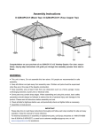
Assembly Instructions
Item# D-GZ848PAL-AS-134
Our clear, easy-to-follow, step-by-step instructions will guide you through the project from start to finish. The final product
will be a quality piece that will go together smoothly and give years of enjoyment.
All you will need is a screwdriver, a hammer and two ladders (not included) whose height is no less than 2.5m.
Note: THIS UNIT IS HEAVY!
Do NOT assemble this item alone for safety. Six people are necessary.
Item Identification: For ease of identification, all parts are labeled to correspond to the Step number in which the part is
used
Parts List
1A (X2)
1C (X2)
1E (x4)
Long side
decorative beam 1
Short side
decorative beam 1
Middle beam
connector
1B (X2)
1D (X2)
Long side
decorative beam 2
Short side
decorative beam 2
1F (x4)
Corner connector
2A (x4)
Top slanting bar
2B (x4)
Middle beam
2C (x4)
Short beam 1
2L (x4)
Short beam 2
2D (x2)
2F (x4)
2H(x4)
2J (x4)
3A(X4)
Right support beam
of long side 1
Right support beam
of long side 3
Left support beam
of long side 2
Right support beam
of short side 2
Slanting bar of
small top
2E (x4)
2G (x2)
2I (x2)
2K (x2)
3B (x4)
3C (x1)
Small top connector
3D (x4)
3E (x1)
Top frame
3F (x2)
3G(x2)
3I (x2)
3K(x1)
4B(X4)
Short support bar of
small top
Roof cover of small
top short side
Pothook
Small base
protector
3H (x2)
3J (x1)
Right support beam
of long side 2
Left support beam
of long side 1
Right support beam
of short side 1
Left support beam
of short side
Cover of small top
Cover of small top
slanting bar
Long support bar of
small top
Roof cover of small
top long side
Roof cover of small
top
4A(X4)
Big base protector
4C(X4)
Big post base
4D(X4)
Small post base
4E(x4)
Big top block
4F (x4)
Small top block
4G1(x2)
Left big post
4G2 (x2)
Right big post
4H2 (x2)
Right small post
4H1
(x2)
4J (x2)
Left small post
Big arc support bar
4K (x2)
4L(x4)
5A(x2)
Arc support bar of
short side1
Screen
4P (x2)
4M(X4)
Left roof cover of
long side 1
5B(x2)
Arc support bar of
short side2
Block plate
Right roof cover
of long side 1
5C(x4)
Left roof cover 1
5D(x4)
Right roof cover 1
5E (x4)
Left roof cover 2
5F (x4)
Right roof cover 2
Middle roof cover
5H(X14
5G (x2)
5I(X8)
5K(X4)
of short side
Short press plate
Bottom cover of
slanting bar
)
5J(X4)
Long press plate
Top cover of
slanting bar
R1(X4)
Curtain tube
connecter 1
R2(X4)
Curtain tube
connecter 2
R3(X4)
Curtain tube
connecter 3
S1(X8)
curtain tube of
long side
S2(X8)
curtain tube of
short side
Hardware Pack 1
AA
M6*15 Bolt
36 PCS
BB
M6 Flat washer
44 PCS
CC
M6*35 Bolt
8 PCS
Z
M6 Wrench
2 PCS
Fig.1:Insert decorative beam 1A(1C)to decorative beam 1B(1D), tighten with bolt (AA) & flat washer (BB).
Fig.2:Attach assembled beams to another respectively and tighten with bolt (CC) & flat washer (BB).
Fig.3:Fix the Middle beam connecter (1E) and curtain tube connecter 1(R1) on the middle of decorative beams by
using bolt (AA) & flat washer (BB)
Fig.4:Fix the Corner connector (1F) on the corner of the decorative beam with bolt (AA) & flat washer (BB).
。
Hardware Pack 2
AA
M6*15 Bolt
32 PCS
BB
M6 Flat washer
136PCS
MM
M6*50 Screw
16PCS
EE
M6*60 Screw
36PCS
FF
M6 Nut
52 PCS
Fig.5: Attach top slanting bar (2A) to top frame (3E) by using bolt (AA) and flat washer (BB).
Fig.6: Attach top slanting bar (2A) to corner connector (1F) by using bolt (EE), flat washer (BB) and nut (FF)
Fig.7: Attach middle beam (2B) to top frame (3E) by using bolt (AA) and flat washer (BB).
Fig.8: Attach middle beam (2B) to middle beam connector (1E) by using bolt (EE), washer (BB) and nut (FF).
Fig.9: Connect Short beam (2L/2C),Top slanting bar (2A) and Short beam 1 (2C) by using bolt ( EE), washer (BB) and
nut (FF).
Fig.10: Attach short beam (2C/2L) to decorative beam by using bolt (AA) and washer (BB).
Fig.11: Connect Left support beam (2G/2K) and Right support beam(2D/2I) to middle beam(2B) by using
bolt (EE),
washer (BB) and nut (FF).
Fig12: Connect Left support beam of long side (2G), Top slanting bar (2A) and Right support beam of short side (2I) by
using bolt (EE), washer (BB) and nut (FF). Connect Left support beam of short side (2K) and Right support
beam of short side 1 (2I) in same way as Fig.12.
Fig.13: Connect Right support beam(2F/2J) and another Right support beam(2F/2J) to Middle beam(2B) by using bolt
(EE), washer (BB) and nut (FF). Note: fix the end of 2F/2J with one connect hole to middle beam (B).
Fig14: Connect another end of Right support beam of long side 3 (2F), Short beam 2 (2L) and Left support beam of
long side 2 (2H) by bolt (MM), washer (BB) and nut (FF). Note: fix the end of 2F with two connect holes to short
beam 2 (2L). Connect another end of Left support beam of long side 2 (2H), Top slanting bar (2A) and Right
support beam of long side 2 (2E) by using bolt (EE), washer (BB) and nut (FF). Connect other support beam in
same way.
Hardware Pack 3
AA
M6*15 Bolt
8 PCS
BB
M6 Flat washer
38 PCS
DD
M6*15 Bolt
12 PCS
EE
M6*60 Bolt
4PCS
LL
M6*40 Bolt
2 PCS
FF
M6 Nut
4 PCS
GG
M6 *35 Bolt
8 PCS
Fig.15: Attach slanting bar of small top (3A) to top frame (3E) by using bolt (DD) and washer (BB).
Fig.16: Attach pothook (3K) to small connector (3C).
Fig.17: Connect slanting bar of small top (3A) and small top connector (3C) by using bolt (EE), washer (BB) and nut
(FF).
Fig.18: Attach long support bar of small top (3F) and short support bar of small top (3G) to top frame (3E) by using bolt
(AA) and washer (BB). 图示显示 3G 和 3F 连在 3A 上,而不是 3E 上。
Fig.19: Put roof cover of small top long side (3H) and short side (3I) onto the slanting bar of small top (3A), then press
cover of small top (3B) on them, fix them by using washer (BB) and bolt (DD) to slanting bar of small top (3A).
(Please note the end of marked “UP” upside.)
Fig.20: Attach cover of small top slanting bar (3D) to cover of small top (3B) by using bolt (GG) and washer (BB).
Attach roof cover of small top (3J) to small top connector (3C) by using bolt (LL) and washer (BB).
Hardware Pack 4
BB
M6 Flat washer
164PCS
DD
M6*15 Bolt
40 PCS
II
M6*20 Bolt
100 PCS
JJ
M6*25 Bolt
24 PCS
KK
Ф8*180 Peg
32 PCS
Fig.21: Lift the big base protector (4A), attach the big post base (4C) to the big post (4G1/G2) with bolt (DD) & washer (BB).
Fig.22: Lift the small base protector (4B), attach the small post base (4D) to the small post (4H) with bolt (DD) & washer
(BB).
Fig.23: Fix big top block (4E) to big post (4G1 & 4G2) with bolt (II) and washer (BB).
Fig.24: Fix small top block (4F) to small post (4H1 & 4H2) with bolt (II) and washer (BB).
Fig.25: Lift assembled gazebo roof frame and fix big top block (4E) to the corner of decorative beam with bolt (II)
and washer (BB).
Fig.26: Fix small top block (4F) to decorative beam (1A/1B) with bolt (II) and washer (BB).
Fig.27: Attach the top of screen (4L) to big post (4G1/4G2) and small post (4H1/4H2) with bolt (II) and flat washer
(BB)
Fig.28: Attach the bottom of screen (4L) to big post (4G1/4G2) and small post (4H1/4H2) with bolt (II) and flat washer (BB)
Fig.29: Attach Big arc support bar (4J) to small post (4H1/H2) with bolt (JJ) and flat washer (BB)
Fig.30: Attach Big arc support bar (4J) to the middle of decorative beam with bolt (II) and flat washer (BB)
Fig.31: Connect the Arc support bar of short side (4K/4P), big post(4G1/4G2) and short side decorative beam
(1C/1D)with bolt (JJ) and flat washer (BB)
Fig.32: Attach Block plate (4M) to big top block (4E) with bolt (DD) and flat washer (BB).
Fig.33: Tighten the curtain tube connecter (R2/R3) on decorative beam (1A/1C) with bolt (II) and flat washer (BB).
(Copy above step to assemble other curtain tube connecters on decorative beam)
Fig.34: Fix the gazebo
on the grass ground with
the peg (KK).
Hardware Pack 5
AA
M6*15 Bolt
52 PCS
BB
M6 Flat
76 PCS
DD
M6*15 Bolt
16 PCS
HH
M6*35 Bolt
8 PCS
Fig.35: Insert left roof cover of long side (5A) to the block of
the bigger top frame, then insert right roof cover of
long side (5B) to the block of the bigger top frame
and press onto 5A.
Fig.36:Fix roof cover of short side (5G) and left roof cover of
long side (5A) to top slanting bar (2A) with bolt (AA)
and washer (BB).
Fig.37: Fix roof cover (5C, 5D, 5E and 5F) to top slanting bar (2A) with bolt (DD) and washer (BB).
Fig.38: Fix press plate 5H (5I) to decorative beam with bolt (AA) and washer (BB).
Fig.39: Insert top cover of slanting bar (5J) into the connect hole of the top frame (3E).
Fig.40: Fix top cover of slanting bar (5J) with bolt (HH) and washer (BB), please do not tighten here, insert bottom
cover of slanting bar (5K) under top cover of slanting bar (5J), fix them with bolt (HH) and washer (BB). Tighten
all bolts here.
Now, your gazebo is ready.
.
IMPORTANT:
1. Keep all children and pets away from assembly area. Children and pets should be supervised when they are in the
area of gazebo construction.
2. The area for assembly should not be less than 6 feet from any obstruction such as fence, garage, house, overhanging
branches, laundry line or electrical wires.
3. This unit is heavy. Do not assemble this item alone. Six people are recommended for safe assembly.
4. Some parts may contain sharp edges. Wear protective gloves if necessary during assembly.
5. When assembling and using this product, basic safety precautions should always be followed to reduce the risk of
personal injury and damage to equipment. Please read all instructions before assembly and use.
6. For outdoor use only. Install on level ground. Stakes are provided to secure the gazebo in grass ground. If you wish to
secure the gazebo to a wood deck or concrete surface, you will need to purchase fasteners appropriate for these
surfaces. These are readily available at your local hardware store or home center.
7. Check all bolts for tightness before and during usage.
8. Please check your state and local regulations prior to purchasing. Some jurisdictions may require permits for, or
otherwise regulate, installation and use.
9. While this gazebo is manufactured to withstand gale force winds utilizing only the supplied ground stakes, in areas
subject to frequent severe weather, securing the gazebo to a deck, concrete patio or footings should be considered.
10. Your gazebo has been engineered to accommodate winter snow loads incurred in most areas. Removal of
accumulated snow on the gazebo roof with a roof rake is recommended.
In areas that are regularly subject to blizzard
conditions however, removal of the roof panel is suggested. The assembled roof structure can simply be left intact until
warmer conditions return.
Limited Warranty:
This limited warranty is extended to the original purchaser and applies to defects in materials and workmanship of your
item provided the item is maintained with care and used only for personal, residential purposes.
The item is warranted to be free from defects in material or workmanship for a period of one (1) year. We don't reimburse
for transportation or delivery costs, or compensate the individual or any outside party for assembling or disassembling
the product.
Exclusions:
Items used for commercial, contract, or other non-residential purposes, or items damaged due to acts of nature,
vandalism, misuse, or improper assembly are not covered. Corrosion or rusting of hardware is not covered. Proof of
purchase (dated register receipt) is required for warranty claims. Warranty is to the original purchaser and is
non-transferable. Any replacement of warranted items will be in the original style and color, or a similar style and color if
the original is unavailable or has been discontinued. As some states do not allow exclusions or limitations on an implied
warranty, the above exclusions and limitations may not apply. This warranty gives you specific rights, and you may also
have other rights, which vary from state to state.
Maintenance:
Our iron/steel components for garden accessories and patio items are coated with rust inhibiting paint that protects it
from rusting. However, due to the nature of iron, surface oxidation (rusting) will occur once these protective coatings are
scratched. This is a natural process and is not a defect! To minimize this condition, we recommend care when
assembling & handling the product to prevent scratching the paint. Should any scratching or damage occur, we
recommend immediate touch-up with rust inhibiting paint. Surface rust can also be easily removed with a very light
application of common cooking oil. If surface oxidation (rusting) occurs and if no measure is taken to prevent this, the
oxidation may start dripping on to deck or patio and cause damaging stains, which may be difficult to remove. This can be
prevented if measure is taken to keep the product from oxidizing.
Important: For technical assistance on assembly or replacement parts. Please call Sunjoy Industries at 1(866) 578-6569
from 8:30 AM to 5:30 PM EST Monday to Friday or fax the replacement part form which is in the box to (740)-283-3549 or
Email [email protected] for assistance.
Made in China
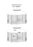
GAZEBO NETTING AND CURTAIN ASSEMBLY INSTRUCTIONS
Netting / Curatin is available separately
Fig.1: Insert the end of curtain tube which has snap hook. And remove the curtain tube (S1/S2) from
curtain tube connecter (R1) as showed in the picture.
Fig.2:Pull out the of curtain tube (S1/S2) which you insert to the from curtain tube connecter (R3)
Fig.3:Slip the curtain (U) over the curtain tube of long side (S1). Please note that there are 6 brass
buckles need to be slipped, then fold the curtain as showed in the picture.
Fig.4: Slip the rest 5 brass buckles on the curtain over curtain tube (S2) and fold the curtain as showed in the
picture.
Fig.5: Uplift the curtain tube assembled with curtain (U) and insert on end of curtain tube to curtain tube
connector. (Please note that you must plug the curtain tube in the end of the connector so that you can
assemble other end of curtain tube easily)
Fig.6: Pull the curtain tube (S1/S2) to the spring fastener on the other hand(不明白是哪个部件), and you can
insert the other side of curtain tube to the curtain tube connecter (R1) exactly.