1
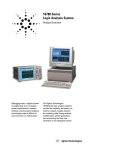
Discontinued Product—Support Information Only
This literature was published years prior to the establishment of Agilent Technologies as a company independent from Hewlett-Packard
and describes products or services now available through Agilent. It may also refer to products/services no longer supported by Agilent.
We regret any inconvenience caused by obsolete information. For the latest information on Agilent’s test and measurement products go to:
www.agilent.com/find/products
Or in the US, call Agilent Technologies at 1-800-452-4844 (8am–8pm EST)
The HP 1660C/CS/CP-Series
Benchtop Logic Analyzers
With compliments
Helmut Singer Elektronik
www.helmut-singer.de [email protected]
fon +49 241 155 315
fax +49 241 152 066
Feldchen 16-24 D-52070 Aachen Germany
Technical Data
Get to the root cause of
problems quickly.
Identifying the cause of problems in The combination of 100-MHz state,
embedded microprocessor system
500-MHz timing, 2-channel 250-MHz
designs can be difficult. The
BW scope, or 32-channel
HP 1660C/CS/CP-series benchtop
200 M Vector/sec pattern generator,
logic analyzers have the features to
internal hard disk drive, and LAN
histograms, state overview, and time
help the design team troubleshoot
make the HP 1660C/CS/CP-series
interval analysis.
hardware and find software defects benchtop logic analyzers especially • The HP E2450A Symbolic Download
quickly. Team members can verify
well suited to finding problems at
Utility is included with the
critical hardware timing relationthe integration stage of prototype
HP 1660C/CS/CP-series. This utility
ships, view processor mnemonics,
hardware and software. [1]
provides the capability to extract
make analog parametric measuresymbolic information from popular
ments, or functionally test their digi- • The internal hard disk drive provides object module formats.
tal design with stimulus.
quick storage and retrieval of files.[1] • Store data as ASCII files and screen
• 3.5-inch high-density flexible disk
images in TIFF, PCX, and EPS
An optional LAN interface enables
drive supports both DOS and LIF
(encapsulated PostScript™) formats.
software designers to capture a real- formats.
• New graphical trigger macros make
time microprocessor trace and time- • LAN interface enables access to the
trigger setup easier.
correlate it to source code in C++ or logic analyzer files via FTP or NFS. • Centronics, RS-232 and HP-IB comother high-level languages on a PC
Use X11 windows and display the
munications ports make connecting
or workstation. For time-correlation logic analyzer user interface on a PC to other devices easier than ever. All
of source code, order the HP B3740A or workstation. [1]
of these come standard on all
Software Analysis package.
• The HP 1660C/CS/CP-series operating HP 1660C/CS/CP-series models.
system includes System Performance • Standard DIN mouse and keyboard
Analysis (SPA). SPA provides state
connectors. A mouse ships with
every HP 1660C/CS/CP-series.[1]
Logic Analyzer Key Specifications and Characteristics
_______________________________________________________________________
HP
Model Number
1660C/CS/CP
1661C/CS/CP 1662C/CS/CP
1663C/CS/CP 1664A
________________________________________________________________________________
State and Timing
136
102
68
34
34
Channels
________________________________________________________________________________
Timing Analysis
Conventional: 250 MHz all channels, 500 MHz half channels
Transitional: 125 MHz all channels, 250 MHz half channels
Glitch: 125 MHz half channels
________________________________________________________________________________
State Analysis Speed
100 MHz, all channels
50 MHz
________________________________________________________________________________
State
Clocks/Qualifiers
6
6
4
2
2
________________________________________________________________________________
Memory Depth
4K per channel, 8K in half-channel modes
per
Channel
________________________________________________________________________________
LAN Port
Standard for CP Model, Option 015 for C/CS model
N/A
________________________________________________________________________________
Pattern
Generator Key Specifications and Characteristics
________________________________________________________________________________
HP
Model Number
1660CP, 1661CP, 1662CP, 1663CP
________________________________________________________________________________
Maximum Clock Speed
200 MHz
100 MHz
50 MHz
________________________________________________________________________________
Number
of Data Channels
16
32
32
________________________________________________________________________________
Memory
Depth,
in
vectors
258,048
258,048
258,048
________________________________________________________________________________
“IF” Command
No
No
Yes
________________________________________________________________________________
[1] Please refer to HP 1664A Product
Specifications and Characteristics on page 9.
PostScript™ is a trademark of Adobe
Systems Incorporated.
Oscilloscope Key Specifications
and Characteristics
____________________________________
Model Number
HP 1660CS, HP 1661CS,
HP 1662CS & HP 1663CS
_______________________________________
Channels
2
_______________________________________
Maximum Sample
1 GSa/s per channel
Rate
_______________________________________
Bandwidth
dc to 250 MHz
(dc coupled)
_______________________________________
Rise Time
1.4 ns
_______________________________________
Vertical
Resolution
8 bits
_______________________________________
Memory Depth per
8k samples
Channel
_______________________________________
2
HP 1660C/CS/CPSeries GeneralProduct Information
_________________________
Human
Interface
_________________________
Front Panel
A knob and keypads
make up the frontpanel human interface.
Keys include control,
menu, display navigation, and alpha-numeric entry functions.
_________________________
Mouse
A DIN mouse is
shipped as standard
equipment. It provides
full instrument control.
Knob functionality is
replicated by holding
down the right button
and moving the mouse
left or right. [1]
_________________________
Keyboard
The logic analyzer can
also be operated using
a DIN keyboard. Order
the HP Logic Analyzer
Keyboard Kit, model
number HP E2427B. [1]
_________________________
Input/Output, Control,
and Printing
_________________________
I/O Ports
All units ship with a
Centronics parallel
printer port, RS-232,
and HP-IB as standard
equipment.[1]
_________________________
LAN Interface An Ethernet LAN interface is available as
option 015. The LAN
interface comes with
both Ethertwist and
ThinLan connectors.
The LAN supports FTP
and PC/NFS connection protocols. It also
works with X11 windows packages. [1][2]
_________________________
Programmability
Each instrument is fully
programmable from a
computer via HP-IB
and RS-232 connections. This feature is
standard on all models.
_________________________
HP Printer
Support
Printers which use the
HP Printer Control
Language (PCL) and
have a parallel
Centronics, RS-232 or
HP-IB interface are
supported:
HP DeskJet, LaserJet,
QuietJet, PaintJet, and
ThinkJet models
_________________________
_________________________
Alternate
Printer
Supported
The Epson FX80, LX80
and MX80 printers with
an RS-232 or Centronics
interface are supported
in the Epson 8-bit
graphics mode.
_________________________
Hard Copy
Output
Screen images can be
printed in black and
white from all menus
using the Print field.
State or timing listings
can be also be printed
in full or part (starting
from center screen)
using the Print All
selection.
_________________________
Mass Storage Files
and
Software
_________________________
Updating the The operating system
Operating
resides in Flash ROM
System
and can be updated
from the flexible disk
drive or from the
internal hard disk
drive. The HP 1664A
boots from disk and
requires only a disk
change to update the
operating system.
_________________________
Mass Storage Supported by an internal hard disk drive and
by a 1.44 Mbyte, 3.5inch flexible disk drive.
Supports DOS and LIF
formats. [1]
_________________________
Screen Image An image file of any
Files
display screen can be
stored to disk via the
display's Print field.
Black & white TIFF,
Grayscale TIFF, PCX,
Encapsulated
PostScript™ (EPS), and
gray-scale TIFF file formats are available.
_________________________
ASCII Data
Files
State or timing listings
can be stored as ASCII
files on a disk via the
display's Print field.
These files are equivalent in character width
and line length to hardcopy listings printed via
the Print All selection.
_________________________
Configuration Logic analyzer and
and Data Files oscilloscope files
that include configuration and data information (if present) are
encoded in a binary
format. They can be
stored to or loaded
from the hard disk drive
or a flexible disk. [1]
_________________________
Recording of
Acquisition
and Storage
Times
Binary format
configuration/data files
are stored with the
time of acquisition and
the time of storage for
all models except the
HP 1664A, which does
not have a real-time
clock.
_________________________
Acquisition Arming
_________________________
Initiation
Arming is started by
Run, Group Run, or the
Port In BNC.
_________________________
Cross Arming Analyzer machines
and the oscilloscope
can cross-arm each
other. [1]
_________________________
Output
An output signal is
provided at the Port
Out BNC.
_________________________
Port
In/Out
_________________________
PORT IN
Signal and
Connection
Port In is a standard
BNC connection.
The input operates at
TTL logic signal levels.
Rising edges are valid
input signals.
_________________________
PORT OUT
Signal and
Connection
Port Out is a standard
BNC connection
with TTL logic
signal levels. A rising
edge is asserted as a
valid output.
_________________________
Skew Adjustment
and
Arming Times
_________________________
Skew
Adjustment
Correction factors for
nominal skew between
displayed timing and
oscilloscope signals
are built into the operating system.
Additional correction
for unit-by-unit variation can be made using
the Skew field. An
entered skew value
affects the next (not
the present) acquisition
display.
_________________________
[1] Please refer to HP 1664A Product Specifications
and Characteristics on page 9.
[2] LAN interface is standard for the HP 1660CP-series,
optional for the HP 1660C/CS-series.
3
HP 1660C/CS/CP-Series
Logic Analyzer Specifications
and Characteristics
_________________________
PORT IN
Arms Logic
Analyzer [3]
15 ns typical delay
from signal input to a
don't care logic
analyzer trigger.
_________________________
PORT IN
40 ns typical delay
Arms
from signal input to an
Oscilloscope immediate oscilloscope
trigger; not available
when oscilloscope is in
time-qualified pattern
triggering mode.
_________________________
Logic
120 ns typical delay
Analyzer
from logic analyzer
Arms PORT trigger to signal
[3]
output.
OUT
_________________________
Oscilloscope 60 ns typical delay from
Arms PORT oscilloscope trigger to
OUT
signal output.
_________________________
_________________________
Physical
Factors
_________________________
[1]
Weight
28.6 lbs. (13 kg)
_________________________
Dimensions
See figure 1
_________________________
Safety
IEC 348/ HD 401,
UL 1244, and
CSA Standard C22.2
No. 231 (series M-89)
_________________________
EMC
CISPR 11:1990/EN 55011 (1991):
Group 1 Class A
IEC 801-2:1991/EN 50082-1 (1992):
4kV CD, 8 kV AD
IEC 801-3:1984/EN 50082-1 (1992): 3 V/m
IEC
801-4:1988/EN 50082-1 (1992): 1kV
_________________________
Operating
Environment
_________________________
Power
115 Vac or 230 Vac,
–22% to +10%, single
phase, 48-66 Hz, 320 VA
max
_________________________
Temperature Instrument, 0° to 50° C
(+32° to 122° F). Disk
media, 10° to 40° C
(+50° to 104°F). Probes
and cables, 0° to 65° C
(+32° to 149° F)
_________________________
Humidity
Instrument, up to 95%,
relative humidity at
+40° C (+140° F). Disk
media and hard drive,
8% to 85% relative
humidity.
_________________________
[1]
Altitude
To 3,048 m (10,000 ft)
_________________________
Vibration:
Operating
Random vibrations
5–500 Hz,
10 minute per axis,
~ 0.3 g (rms).
_________________________
Vibration:
Random vibrations
Non Operating 5–500 Hz,10 minutes per
axis,~ 2.41 g (rms); and
swept sine resonant
search, 5–500 Hz,
0.75 g (0-peak),
5 minute resonant dwell
@ 4 resonances per
axis.
_________________________
17.3 inches
(440 mm)
Weight 28.6 lbs (13 kg)
Figure 1
_________________________
Logic
Analyzer Probes
_________________________
Input
100 kΩ ±2%
Resistance
_________________________
Input
approx. 8 pF
Capacitance
(see figure 2)
_________________________
RT = 250Ω
CTG = 1 pF
CCOMP = 7.5 pF
RIN = 100kΩ
Z0 =
150Ω
High Frequency Model for Probe Inputs
Figure 2
_________________________
Minimum
500 mV peak-to-peak
Input Voltage
Swing
_________________________
Minimum
250 mV or 30% of input
13.0 in. 14.5 in.
(330 mm) (367 mm) Input
amplitude, whichever is
Overdrive
greater
_________________________
Threshold
–6.0 V to +6.0 V in 50-mV
Range
increments
_________________________
Threshold
Threshold levels may be
Setting
defined for pods
(17-channel groups) on
8.1 in.
(205 mm)
an individual basis
_________________________
Threshold
± (100 mV +3% of
Accuracy*
threshold setting)
_________________________
Input
± 10 V about the
Dynamic
threshold
Range
_________________________
Maximum
± 40 V peak
Input
Voltage
_________________________
+5 V
1/3 amp maximum
Accessory per pod
Current
_________________________
Channel
Each group of 34
Assignment channels (a pod pair)
can be assigned to
Analyzer 1, Analyzer 2
or remain unassigned.
_________________________
[1] Please refer to HP 1664A product specifications
and characteristics on page 9.
[3] Time may vary depending upon the mode of logic
analyzer operation.
* Warranted specification.
With compliments
Helmut Singer Elektronik
4
www.helmut-singer.de [email protected]
fon +49 241 155 315
fax +49 241 152 066
Feldchen 16-24 D-52070 Aachen Germany
______________________________
_________________________
State
Analysis
_________________________
Minimum
10.0 ns
Slave to
Slave
Clock
Time [5]
_________________________
Maximum
100 MHz all models
State
except HP 1664A,
Speed*
which is 50 MHz
_________________________
HP 1660C, CS, CP 136/68
HP 1661C, CS, CP 102/51
HP 1662C, CS, CP 68/34
HP 1663C, CS, CP 34/17
HP 1664A
34/17
_________________________
Channel
Count [4]
Memory
4096/8192 samples
Depth per
[4]
Channel
_________________________
State Clocks
HP 1660C, CS, CP
HP 1661C, CS, CP
HP 1662C, CS, CP
HP 1663C, CS, CP
HP 1664A
6 clocks
6 clocks
4 clocks
2 clocks
2 clocks
Clocks can be used by
either one or two state
analyzers at any time,
except for the 1663C,
1663CS, 1663CP and
1664A models, which
can have only one
state or timing analyzer.
Clock edges can be
ORed together and
operate in single
phase, two-phase
demultiplexing, or twophase mixed mode.
Clock edge is
selectable as positive,
negative, or both edges
for each clock.
_________________________
The high or low of up to
4 of the 6 clocks can be
ANDed or ORed with
the clock specification.
_________________________
State Clock
Qualifier
Setup/Hold* [5]
one clock,
3.5/0 ns to 0/3.5 ns
one edge
(in 0.5 ns increments)
one clock,
both edges
4.0/0 ns to 0/4.0 ns
(in 0.5 ns increments)
Minimum
0.0 ns
Master to
Slave
Clock
Time [5]
_________________________
Minimum
4.0 ns
Slave to Master
Clock
Time [5]
_________________________
4 ns/2 ns minimum,
8.38 ms maximum
Memory
Depth per
Channel [4]
4096/8192 samples
Time Covered Sample period ×
by Data
memory depth
16.3 µs min,
34.4 sec/68.6 sec max
_________________________
Transitional
Timing
Sample is stored in
acquisition memory
only when the data
changes. A time tag
stored with each
sample allows reconstruction of waveform
display. Time covered
by a full memory
acquisition varies with
the number of pattern
changes in the data.
Maximum
Timing
Speed [4]
125 MHz/250 MHz
Channel
Count [4]
HP 1660C, CS, CP, 136/68
HP 1661C, CS, CP 102/51
HP 1662C, CS, CP 68/34
HP 1663C, CS, CP 34/17
HP 1664A
34/17
Sample
Period [4]
8 ns/4 ns
Clock
4.0/0 ns (fixed)
Qualifiers
[5]
Setup/Hold
_________________________
State
Tagging [6]
Counts the number of
qualified states
between each stored
state. Measurement
can be shown relative
to the previous state or
relative to trigger. Max.
count is 4.29 × 10⁹.
0 to 4.29 × 10⁹
State Tag
Count
State Tag
1 count
Resolution
_________________________
Measures the time
between stored states,
relative to either the
previous state or to the
trigger. Max. time
between states is
34.4 sec. Min. time
between states is 8 ns.
Time Tag
8 ns to 34.4 seconds
Value
± (8 ns + 0.01% of time
tag value)
Time Tag
8 ns or 0.1%
Resolution
(whichever is greater)
_________________________
Time
Tagging [6]
Timing
Analysis
_________________________
Conventional Data stored at selected
Timing
sample rate across all
timing channels.
multi-clock, 4.5/0 ns to 0/4.5 ns
multi-edge
(in 0.5 ns increments)
_________________________
Maximum
Timing
Speed [4]
250 MHz / 500 MHz
Minimum
3.5 ns
State Clock
Pulse
Width* [5]
_________________________
Channel
Count [4]
HP 1660C, CS, CP 136/68
HP 1661C, CS, CP 102/51
HP 1662C, CS, CP 68/34
HP 1663C, CS, CP 34/17
HP 1664A
34/17
Minimum
10.0 ns
Master to
Master
Clock
Time* [5]
_________________________
Sample
Period [4]
Time Covered 16.3 µs minimum,
9.7 hrs./6.5 hrs.
by Data [4]
maximum
Maximum
34.4 s
Time
Between
Transitions
Number of
1023-2047/682-4094
Captured
Depending on input
[4] signals
Transitions
_________________________
[4] Full Channel /Half Channel Modes
[5] Specified for an input signal VH= – 0.9V, VL = – 1.7V,
slew rate = 1V/ns, and threshold = –1.3V
[6] Time or-state-tagging (Count Time or Count State)
is available in the full-channel state mode. There is
no speed penalty for tag use. Memory is halved
when time or state tags are used unless a pod pair
(34-channel group) remains unassigned in the
Configuration menu.
* Warranted specification.
5
_________________________
Glitch
Capture
Mode
Data sample and glitch
information is stored
every sample period
Maximum
125 MHz
Timing Speed
Channel
Count
HP 1660C ,CS, CP 68
HP 1661C, CS, CP 51
HP 1662C, CS, CP 34
HP 1663C, CS, CP 17
HP 1664A
17
8 ns minimum, 8.38 ms
maximum
3.5 ns
_________________________
_________________________
Pattern
Recognizers
Each recognizer is the
AND combination of bit
(0,1, or X) patterns in
each label.
Pattern
Recognizers
10
Greater than Sample period 2-8 ns:
Duration
8 ns to 8.389 ms.
(timing only) Accuracy is –2 ns to
+10 ns
Sample period > 8 ns:
(1 to 220) × sample
period. Accuracy is
–2 ns + sample period
+ 2 ns ± 0.01%
_________________________
Pattern Width HP 1660C, CS, CP136/68
(in channels)[4] HP 1661C, CS, CP102/51
HP 1662C, CS, CP 68/34
HP 1663C, CS, CP 34/17
HP 1664A
34/17
_________________________
Sample period 2-8 ns:
8 ns to 8.389 ms.
Accuracy is –2 ns to
Sample
+10 ns.
Period
Minimum
250 MHz and 500 MHz
Sample period > 8 ns:
Minimum
Pattern
Timing
Modes:
13
ns
+
(1
to 220) × sample
Glitch Width*
and Range
channel-to-channel
period.
Maximum
Sample Period – 1 ns
Recognizer skew
Accuracy is 2 ns +
Glitch Width
Pulse Width ≤ 125 MHz Timing
sample period – 2 ns ±
Modes : 1 sample period _________________________
0.01%
Memory
2048 samples
+ 1 ns + channel-toQualifier
A user-specified term
Depth per
channel skew + 0.01%
_________________________
that can be any state,
Channel
Range
Recognize data which is
no state, any recognizer,
Time Covered Sample Period × 2048:
Recognizers numerically between or
(pattern, ranges or
by Data
16.3 µs minimum,
on two specified patedge/glitch), any timer,
17.1 sec maximum
terns (ANDed combinaor the logical combina_________________________
tion
of
zeros
and/or
tion (NOT, AND, NAND,
Time
Interval Accuracy
_________________________
ones).
OR, NOR, XOR, NXOR) of
the recognizers and
Sample
± 0.01%
Range
2
timers.
Period
_________________________
Accuracy
_________________________ Recognizers
Branching
Each sequence level
has a branching qualifiChannel-to- 2 ns typical,
Range Width 32 channels
_________________________
er. When satisfied, the
Channel
Skew3
ns
maximum
_________________________ Edge/Glitch Trigger on glitch or
analyzer will branch to
Time Interval ± (Sample Period
Recognizers edge on any channel.
the sequence level
Accuracy
Accuracy + channel-toEdge can be specified
specified.
_________________________
channel skew + 0.01%
as rising, falling or
of time interval reading)
either.
_________________________
Sample Period 2-8 ns :
8.389 ms
Sample Period > 8 ns:
1,048,575 × sample
period
_________________________
Maximum
Delay
After
Triggering
Trigger Specifications
_________________________
Edge/Glitch
Recognizers
2 (in timing mode only)
Edge/Glitch
Width (in
channels) [4]
HP 1660C, CS, CP136/68
HP 1661C, CS, CP102/51
HP 1662C, CS, CP 68/34
HP 1663C, CS, CP 34/17
HP 1664A
34/17
Trigger setups can be
selected from a categoEdge/Glitch Sample Period 2-8 ns:
rized list of trigger
macros. Each macro is Recovery Time 28 ns
Sample Period > 8 ns:
shown in graphical
20 ns + sample period
form and has a written _________________________
description. Macros
can be chained together to create a custom
trigger sequence.
_________________________
Trigger
Macros
Less than
Duration
(timing only)
[4] Full Channel /Half Channel Modes
* Warranted specification
With compliments
Helmut Singer Elektronik
6
www.helmut-singer.de [email protected]
fon +49 241 155 315
fax +49 241 152 066
Feldchen 16-24 D-52070 Aachen Germany
_________________________
Occurrence
Counters
Sequence qualifier may
be specified to occur up
to 1,048,575 times before
advancing to the next
level. Each sequence
level has its own
counter.
Maximum
1,048,575
Occurrence
Count
_________________________
Storage
Each sequence level
Qualification has a storage qualifier
(state only)
that specifies the states
that are to be stored.
_________________________
Maximum
Sequencer
Speed
125 MHz
State
Sequence
Levels
12
Timing
10
Sequence
Levels
_________________________
Timers
Timers may be Started,
Paused, or Continued at
entry into any sequence
level after the first.
Timers
2
Timer Range
400 ns to 500 seconds
Timer
Resolution
16 ns or 0.1% whichever
is greater
Timer
Accuracy
± 32 ns or ± 0.1%,
whichever is greater
Timer
70 ns
Recovery
Time
_________________________
Data In to
110 ns typical
Trigger Out
BNC
Port
_________________________
_________________________
Acquisition, Measurement
and
Display Functions
_________________________
Each analyzer can be
armed by the Run key,
the other analyzer, the
oscilloscope (CS models
only), the pattern generator (CP Models only) or
the Port In. [1]
_________________________
Arming
Starts acquisition of
data in specified trace
mode.
_________________________
Run
In single trace mode or
the first run of a repetitive acquisition, Stop
halts acquisition and
displays the current
acquisition data. For
subsequent runs in
repetitive mode, Stop
halts acquisition of
data and does not
change current display.
_________________________
Stop
Single mode acquires
data once per trace
specification; repetitive
mode repeats single
mode acquisitions until
Stop is pressed or until
pattern time interval or
compare stop criteria
are met.
_________________________
Trace Mode
Displayed as a vertical
dashed line in the
timing waveform, state
waveform and X-Y
chart displays and as
line 0 in the state listing
and state compare displays.
_________________________
Trigger
_________________________
Channels may be
grouped together and
given a 6-character
name called a label. Up
to 126 labels in each
analyzer may be
assigned with up to 32
channels per label.
Trigger terms may be
given an 8-character
name.
_________________________
Labels
Measurement
Functions
_________________________
Two markers (x and o)
are shown as dashed
lines in the display.
_________________________
Markers
The x and o markers
measure the time
interval between events
occurring on one or
more waveforms or
states (available in state
when time tagging is on).
_________________________
Time
Intervals
Delta States The x and o markers
measure the number of
tagged states between
any two states (state
only).
_________________________
The x or o marker can
be used to locate the
nth occurrence of a
specified pattern
before or after trigger,
or after the beginning
of data. The o marker
can also find the nth
occurrence of a pattern
before or after the x
marker.
_________________________
Patterns
x to o marker statistics
are calculated for
repetitive acquisitions.
Activity
Provided in the
Patterns must be speciIndicators
Configuration, State
fied for both markers,
Format, and Timing
and statistics are kept
Format menus for monionly when both pattoring device-underterns can be found in
test activity while setan acquisition.
ting up the analyzer.
_________________________
Statistics are minimum
x to o time, maximum x
to o time, average x to
o time, and ratio of
valid runs to total runs.
_________________________
Statistics
1] Please refer to HP 1664A Product Specifications
and Characteristics on page 9.
7
_________________________
_________________________
Compare
Mode
Functions
Performs post-process
ing bit-by-bit
comparison of the
acquired state data and
Compare Image data.
State X-Y
Plots value of a speciChart Display fied label (on y-axis)
versus states or another
label (on x-axis). Both
axes can be scaled.
Compare
Image
Created by copying a
state acquisition into
the compare image
buffer. Allows editing of
any bit in the Compare
Image to a 1, X or O.
Markers
Compare
Image
Boundaries
Each channel (column)
in the Compare Image
can be enabled or disabled via bit masks in
the Compare Image.
Upper and lower ranges
of states (rows) in the
compare image can be
specified. Any data bits
that do not fall within
the enabled channels
and the specified range
are not compared.
Correlated to State
Listing, State Compare,
and State Waveform
displays. Available as
pattern, time, or statistics (with time counting)
and states (with state
counting on).
Accumulate
Chart display is not
erased between successive acquisitions.
_________________________
Displayed
Waveforms
24 lines maximum on
one screen. Up to 96
lines may be specified
and scrolled through.
_________________________
System
SPA includes state
Performance histogram, state
Analysis
overview and time
interval measurements
to aid in the software
optimization process.
These tools provide a
statistical overview of
your synchronous
design.
_________________________
State
Waveform
Display
Displays state
acquisitions
in waveform format.
Binary, Octal, Decimal,
Hexadecimal, ASCII
(display only), Userdefined symbols, two's
complement.
_________________________
States/div.
1 to 1000 states.
Symbols
Delay
– 8191 to + 8192 states.
Pattern
Symbols
Accumulate
Stop
Repetitive acquisitions
Measurement may be halted when
the comparison
between the current
state acquisition and the
current Compare Image
is equal or not equal.
_________________________
Waveform display is not
erased between successive acquisitions.
Overlay
Mode
Multiple channels can
be displayed on one
waveform display line.
User can define a
mnemonic for the specific bit pattern of a
label. When data display
is SYMBOL, mnemonic is
displayed where the bit
pattern occurs.
Range
Symbols
Reference Listing
display shows the
Compare Image and
bit masks; Difference
Listing display highlights
differences between
the current state
acquisition and the
Compare Image.
_________________________
Timing
Waveform
Display
Displays timing
acquisition in waveform format.
User can define a
mnemonic covering a
range of values. When
data display is SYMBOL,
values within the specified range are displayed
as mnemonic + offset
from base of range.
Sec/div
1 ns to 1000 s; 0.01%
resolution.
Data
Entry/Display
_________________________
Delay
– 2,500 s to + 2,500 s
State Listing, State
Waveforms, State Chart,
State Compare Listing,
Compare Difference
Listing, Timing
Waveforms, Timing
Listing, interleaved timecorrelated listing of two
state analyzers (time
tags on), and time-correlated State Listing with
Timing Waveforms on
the same display.
_________________________
Accumulate
Waveform display is
not erased between
successive acquisitions.
Compare
Mode
Displays
Display
Modes
Displayed
Waveforms
24 lines maximum on
one screen. Up to 96
lines may be specified
and scrolled through.
_________________________
Overlay Mode Multiple channels can
be displayed on one
waveform display line.
When waveform size
set to large, the value
represented by each
waveform is displayed
inside the waveform in
the selected base.
Bases
Number of
1000 maximum.
Symbols
_________________________
8
HP 1660CS-Series
Oscilloscope
Specifications and
Characteristics [1]
__________________________________
__________________________________
General
Information
______________________________
Horizontal
______________________________
Model
HP 1660CS, 1661CS,
Numbers
1662CS, 1663CS
______________________________
Number of
2
Channels
______________________________
Maximum
1 GSa/s per channel
Sample
Rate
______________________________
Bandwidth
dc to 250 MHz
[7] [11]
(real time, dc coupled)
______________________________
Rise Time
1.4 ns
[8] [11]
______________________________
Vertical
8 bits
Resolution
______________________________
Memory
Depth 8k samples
______________________________
Time Base
1 ns/div to 5 s/div
Range
______________________________
Time Base
20 ps ± [(0.005% of Δt)
Resolution
+ (2 × 10– 6 × delay
setting) + 150 ps]
______________________________
Maximum
– 4 µs to – 40 s
Negative
(depending on the
Acquisition sample rate)
Delay
______________________________
Maximum
16.7 ms to 2.5 ks
Positive
(depending on
Acquisition sample rate)
Delay
______________________________
Time Interval ± [(0.005% of Δt)
Measurement + (2×10 – 6 × delay
Accuracy
setting) + 150 ps]
[10] [11]
______________________________
Oscilloscope
Probing
______________________________
Input Coupling1 MΩ: ac,dc
50 Ω: dc only
______________________________
1MΩ ± 1%
Input R [11]
50Ω ± 1%
______________________________
Input
C
~ 7pF
______________________________
Probes
Two HP 10430A probes;
Included
10:1, 1 MΩ 6.5 pF
______________________________
Vertical
(at BNC)
______________________________
Maximum
1 MΩ : ±250 V
Safe Input
50 Ω : 5 V rms
Voltage
______________________________
Vertical
1 MΩ: ±250 V
Sensitivity
(ac + dc, <10 kHz)
Range
50 Ω: 5 V rms
(1:1
Probe)
______________________________
Probe Factors Any integer ratio from
1:1 to 1000:1
______________________________
Vertical (dc) ± 1.25% of full scale
Gain
[9]
Accuracy
______________________________
dc Offset
± 2V to ± 250V
Range
(depending on the
(1:1
probe)
vertical sensitivity)
______________________________
dc Offset
± [1.0% of channel
Accuracy [11] offset
+ 2.0% of full scale]
______________________________
Voltage
± [1.25% of full scale
Measurement + offset accuracy
[11] + 0.016 V/div]
Accuracy
______________________________
Channel-to- dc to 50 MHz – 40 dB
Channel
50 MHz to 250 MHz
Isolation
– 30 dB
______________________________
Oscilloscope
Triggering
______________________________
Trigger Level Bounded within chanRange
nel display window
______________________________
Trigger
dc to 50 MHz:
Sensitivity [11] 0.063 × Full Scale
50 MHz to 250 MHz:
0.125 × Full Scale
______________________________
Trigger Modes
Immediate
Triggers immediately
after arming condition is
met. (Arming condition
is Run, Group Run,
cross arming signal, or
Port In BNC signal).
Edge
Triggers on rising or
falling edge from channel 1 or 2.
Triggers on entering or
exiting logical pattern
specified across channels 1 or 2. Each channel can be specified as
high (H), low (L), or don't
care (X) with respect to
the level settings in the
edge trigger menu.
Patterns must be
>1.75 ns in duration to
be recognized.
______________________________
______________________________
Time-Qualified Triggers on the exiting
Pattern
edge of a pattern which
meets the user-specified duration criterion.
Greater than, less than,
or within range duration criterion can be
used. Duration range is
20 ns to 160 ns. Recovery time after valid patterns with invalid duration is <12 ns.
Events Delay Triggers on the nth
edge or pattern as
specified by the user.
Time-qualification is
applied only to the 1st
of n patterns.
______________________________
Auto-Trigger Self-triggers if no trigger condition is found
~ 50 ms after arming.
______________________________
Measurement
Functions
______________________________
Time Markers Two markers (x and o)
measure time intervals
manually, or automatically with statistics.
______________________________
Voltage
Two markers (a and b)
Markers
measure voltage and
voltage differences.
______________________________
Automatic
Period, frequency,
Measurementsrise time, fall time,
+width, –width, peakto-peak voltage, overshoot, and undershoot.
______________________________
Pattern
[7] Upper bandwidth reduces by 2.5 MHz for every
degree C above 35°C.
[8] Rise time calculated as tr =
0.35
bandwidth
[9] Vertical gain accuracy decreases 0.08% per
degree C from software calibration temperature.
[10] Specification applies at the maximum sampling
rate. At lower rates, replace 150 ps in the formula
with ( 0.15 × sample interval) where sample interval is defined as 1/sample rate.
[11] Specifications (valid within ± 10°C of auto-calibration temperature)
HP 1660CP-Series Pattern
Generator Characteristics
9
______________________________
The HP 1664A Specifications
and Characteristics
______________________________
The HP 1664A is a low cost version of
the HP 1660C/CS/CP-series logic analyzer family. The HP 1664A has some
specifications and characteristics that
are different from the HP 1660C/CS/CPseries logic analyzers.
•
•
•
•
•
•
•
•
•
•
•
•
•
•
The HP 1664A:
Supports a maximum of 50 MHz state
acquisition
Supports all modes of timing analysis
Weight 26 pounds (11.8 kg)
Altitude To 15,000 ft (4,752 m)
Boots from the floppy disk drive—it
does not have flash ROM
It cannot be upgraded to include an
oscilloscope or pattern generator
Channel count upgrades are not
available
The mouse and keyboard connectors
are HP HIL standard
For the optional keyboard order
HP E2427A
It cannot be upgraded to a C model
It does not support the HP B3740A
software analyzer software
It does not support the HP E2450A
Symbol Download Utility
It does not support the software performance analysis software
It does not have a hard disk drive
• It cannot have a LAN port added
Maximum memory depth
258,048 vectors
Number of output channels at 100 MHz to 200 MHz clock
16
Number of output channels at ≤100 MHz clock
32
Maximum number of “IF Condition” blocks at ≤50 MHz clock
1
Maximum number of different macros
100
Maximum number of lines in a macro
1024
Maximum number of parameters in a macro
10
Maximum number of macro invocations
1,000
Maximum loop count in a repeat loop
20,000
Maximum number of repeat loop invocations
1,000
Maximum number of Wait event patterns
4
Number of input lines to define a wait pattern
3
Maximum width of a label
32 bits
Maximum number of labels
126
Lead Set Characteristics
HP 10474A 8-channel probe lead set
Provides most cost effective lead set for the
HP 1660CP-series clock and data pods. Grabbers are
not included.
HP 10347A 8-channel probe lead set
Provides 50 Ω coaxial lead set for unterminated signals,
required for HP 10465A ECL Data Pod (unterminated).
Grabbers are not included.
Data Pod Characteristics
HP 10461A TTL DATA POD
Output type
10H125 with 100 Ω series
Maximum clock
200 MHz
Skew (note 1)
typical < 2 ns; worst case = 4 ns
Recommended lead set
HP 10474A
100 Ω
ECL/TTL
10H125
HP 10462A 3-STATE TTL/CMOS DATA POD
Output type
74ACT11244 with 100 Ω series; 10H125 on non 3-state channel 7 (note 2)
3-state enable
negative true, 100 KΩ to GND, enabled on no connect
Maximum clock
100 MHz
Skew (note 1)
typical < 4 ns; worst case = 12 ns
Recommended lead set
HP 10474A
74ACT11244
100 Ω
With compliments
Helmut Singer Elektronik
www.helmut-singer.de [email protected]
fon +49 241 155 315
fax +49 241 152 066
Feldchen 16-24 D-52070 Aachen Germany
With compliments
Helmut Singer Elektronik
10
www.helmut-singer.de [email protected]
fon +49 241 155 315
fax +49 241 152 066
Feldchen 16-24 D-52070 Aachen Germany
Clock Pod Characteristics
HP 10464A ECL DATA POD (TERMINATED)
Output type
10H115 with 330 Ω pulldown, 47 Ω series
Maximum clock
200 MHz
10460A TTL CLOCK POD
Skew (note 1)
typical < 1 ns; worst case = 2 ns
Clock output type
Recommended lead set
HP 10474A
10H125 with 47 Ω
series; true & inverted
Clock output rate
100 MHz maximum
Clock out delay
11 ns maximum in 9
steps
Clock input type
TTL – 10H124
Clock input rate
dc to 100 MHz
Pattern input type
TTL – 10H124
(no connect is logic 1)
approximately 30 ns
47 Ω
10H115
330 Ω
– 5.2 V
HP 10465A ECL DATA POD (UNTERMINATED)
Output type
10H115 (no termination)
Clock-in to clock-out
Maximum clock
200 MHz
Skew (note 1)
typical < 1 ns; worst case = 2 ns
Pattern-in to recognition approx. 15 ns + 1 clk
period
Recommended lead set
HP 10347A
Recommended lead set
HP 10474A
47Ω
CLKout
10H125
10H115
HP 10466A 3-STATE TTL/3.3 VOLT DATA POD
WAIT
10H124
CLKin
Output type
74LVT244 with 100 Ω series; 10H125 on non 3-state channel 7 (note 2)
3-state enable
negative true, 100 KΩ to GND, enabled on no connect
10463A ECL CLOCK POD
Maximum clock
200 MHz
Clock output type
Skew (note 1)
typical < 3 ns; worst case = 7 ns
Recommended lead set
HP 10474A
10H116 differential
unterminated; and
differential with 330 Ω
to –5.2V and 47 Ω
series
Clock output rate
200 MHz maximum
Clock out delay
11 ns maximum in 9
steps
Clock input type
ECL – 10H116 with
50 KΩ to –5.2v
Clock input rate
dc to 200 MHz
Pattern input type
ECL – 10H116 with
50 KΩ no connect is
logic 0)
Clock-in to clock-out
approximately 30 ns
100 Ω
74LVT244
Note 1: Typical skew measurements made at pod connector with approximately 10 pF/50 KΩ load to GND;
worst case skew numbers are a calculation of worst case conditions through circuits. Both numbers
apply to any channel within a single or multiple module system.
Note 2: Channel 7 on the 3-state pods has been brought out in parallel as a non 3-state signal. By looping
this output back into the 3-state enable line, the channel can be used as a 3-state enable.
Data Cable Characteristics Without a Data Pod
Pattern-in to recognition approx. 15 ns + 1 clk
period
The HP 1660CP data cables without a data pod provide an ECL terminated (1 KΩ to –5.2V) differential signal (from a type 10E156 or 10E154 driver). These are usable when received by a differential
receiver, preferably with a 100 Ω termination across the lines. These signals should not be used
single ended due to the slow fall time and shifted voltage threshold (they are not ECL compatible).
Recommended lead set
HP 10474A
CLKin
10H116
HP 1660CP DATA CABLE OUTPUT
VBB
–5.2 V
–5.2 V
50 kΩ
–5.2 V
1 kΩ
330 Ω
10H116
10E156
or
10E154
Differential
Output
1 kΩ
–5.2 V
47 Ω
CLKout
HP 1660C/CS/CP-Series
Ordering Information
11
HP
1660C/CS/CP Series Benchtop Logic Analyzers
__________________________________________________________________________________________________
HP 1660C
136-Channel 100-MHz State/500-MHz Timing
__________________________________________________________________________________________________________________________
HP
1660CS
136-Channel 100-MHz State/500-MHz Timing with Integrated 2-Channel 1-GSa/s Oscilloscope
__________________________________________________________________________________________________________________________
HP
1660CP
136-Channel 100-MHz State/500-MHz Timing with Integrated 32-Channel 200M Vectors /sec Pattern Generator and Ethernet LAN[13]
__________________________________________________________________________________________________________________________
HP
1661C
102-Channel 100-MHz State/500-MHz Timing
__________________________________________________________________________________________________________________________
HP
1661CS
102-Channel 100-MHz State/500-MHz Timing with Integrated 2-Channel 1-GSa/s Oscilloscope
__________________________________________________________________________________________________________________________
HP 1661CP
102-Channel 100-MHz State/500-MHz Timing with Integrated 32-Channel 200M Vectors /sec Pattern Generator and Ethernet LAN[13]
__________________________________________________________________________________________________________________________
HP
1662C
68-Channel 100-MHz State/500-MHz Timing
__________________________________________________________________________________________________________________________
HP
1662CS
68-Channel 100-MHz State/500-MHz Timing with Integrated 2-Channel 1-GSa/s Oscilloscope
__________________________________________________________________________________________________________________________
HP
1662CP
68-Channel 100-MHz State/500-MHz Timing with Integrated 32-Channel 200M Vectors /sec Pattern Generator and Ethernet LAN[13]
__________________________________________________________________________________________________________________________
HP
1663C
34-Channel 100-MHz State/500-MHz Timing
__________________________________________________________________________________________________________________________
HP 1663CS
34-Channel 100-MHz State/500-MHz Timing with Integrated 2-Channel 1-GSa/s Oscilloscope
__________________________________________________________________________________________________________________________
HP
1663CP
34-Channel 100-MHz State/500-MHz Timing with Integrated 32-Channel 200M Vectors /sec Pattern Generator and Ethernet LAN[13]
__________________________________________________________________________________________________________________________
HP
1664A
34-Channel 50-MHz State/500-MHz Timing
__________________________________________________________________________________________________________________________
Logic
Analyzer Probes
________________________________________________________________
Every HP 1660-Series logic analyzer ships standard with a complete probe kit that contains all of the
acquisition cables (p/n 01660-61605), lead sets (01650-61608), grabbers (5090-4356) and other accessories that you require for general purpose logic analysis. The HP 1660CP-Series requires the appropriate clock and data pods to be ordered as options as noted below.
Additional
HP 1660C/CS/CP Series Product Options
________________________________________________________________
Option 015
Ethernet LAN interface [13]
Option 0B1
Extra User Manual
Option OB3
Add Service Manual
Option OBF
Add Programming Manual
Option 908
Rack Mount Kit
Option UK9
Front Panel Cover
Option W30 3-Year extended repair service
Option
W50 5-Year extended repair service
________________________________________________________________
Accessory
Software
______________________________
Software Analyzer
IBM, 3.5" Media/Documentation
HP 9000 Series 700
Media/Documentation
Opt AAV
SUN (Solaris and SUN OS)
Media/Documentation
Opt UDY
IBM Single User License
Opt UBY
HP 9000 Series 700 Single User
License
Opt UBK
SUN (Solaris and SUN 0S) Single
User License
______________________________________
HP 10391B
Inverse Assembler
Development Package
______________________________________
HP B3740A
Opt AJ4
Opt AAY
HP
1660CP Series Required Product Options
________________________________________________________________
Option 011
TTL Clock Pod and Lead Set (1 ea 10460A + 1 ea 10474A)
Option 012
3-state TTL/3.3V Data Pod and Lead Set (1 ea 10466A + 1 ea 10474A)
Option 013
3-state TTL/CMOS Data Pod and Lead Set (1 ea 10462A + 1 ea 10474A)
Option 014
TTL Data Pod and Lead Set (1 ea 10461A + 1 ea 10474A)
Option 021
ECL Clock Pod and Lead Set (1 ea 10463A + 1 ea 10474A)
Option 022
ECL (terminated) Data Pod and Lead Set (1 ea 10464A + 1 ea 10474A)
Option
023
ECL (unterminated) Data Pod and Lead Set (1 ea 10465A + 1 ea 10347A)
________________________________________________________________
Note: For the pattern generator of HP 1660CP-series, please order at least one clock pod and at least one
data pod for every eight (8) output channels from the above options or accessories listed on page 12.
HP 1660C/CS/CP Series Upgrades
________________________________________________________________
Upgrade to add two-channel 1-GSa/s, 250-MHz BW oscilloscope to any of the
HP 1660CS series (oscilloscope upgrade does not apply to HP 1660A-series)
_________________________________________________________________________________
HP E2495A [12]
Upgrade to add 32-channel, 200 M Vectors/sec pattern generator (this
upgrade does not apply to the HP 1660CS-series and HP 1664A)
_________________________________________________________________________________
HP
E2427B
Add keyboard with DIN connector (PC style)
_________________________________________________________________________________
HP
E2427A
Add keyboard with HIL connector (HP 1664A only)
_________________________________________________________________________________
HP E2460CS [12]
HP E2472A [12]
Upgrade to add LAN capability to HP 1660C/CS series (this upgrade does not
apply to the HP 1664A)
_________________________________________________________________________________
HP E2460B† [12]
Upgrades HP 1661C/CS to 136-channel HP 1660C/CS model, option 001
upgrades channel count of HP 1662C/CS to 1660C/CS, option 002 upgrades
channel count of HP 1663C/CS to 1660C/CS
_________________________________________________________________________________
HP E2461B† [12]
Upgrades HP 1662C/CS to 102-channel 1661C/CS model, option 001 upgrades
channel count of 1663C/CS to 1661C/CS
_________________________________________________________________________________
† [12]
HP
E2462B
Upgrades HP 1663C/CS to 64-channel 1662C/CS model
_________________________________________________________________________________
HP E2469A [12]
Upgrade HP 1660A/AS series to HP 1660C/CS series (includes LAN capability—do not order additional HP E2472A)
_________________________________________________________________________________
[12] Upgrade includes cost of installation at a HewlettPackard Service Center. Upgrade is not customer
installable.
[13] Ethernet LAN interface is included standard on the
HP 1660CP-series and HP 1670D-series models.
LAN is optional on the HP 1660C-series and
HP 1660CS-series. LAN is not available on the
HP 1664A.
† Channel count upgrades do not apply to the
HP 1664A.
With compliments
Additional Ordering Information
Helmut Singer Elektronik
www.helmut-singer.de [email protected]
fon +49 241 155 315
fax +49 241 152 066
Feldchen 16-24 D-52070 Aachen Germany
HP
01650-61608
16-Channel probe lead set for state and timing analyzers
________________________________________________________________________________
HP 01650-63203
Termination adaptor for state and timing analyzers
________________________________________________________________________________
HP 1810-1278
9-Channel IC termination (DIP)
________________________________________________________________________________
HP 1810-1588
Termination IC SIP
________________________________________________________________________________
For more information about
Hewlett-Packard test & measurement
products, applications, services, and
for a current sales office listing, visit
our web sites:
http://www.hp.com/go/tmdir
http://www.hp.com/go/logicanalyzer
http://www.hp.com/go/emulator
You can also contact one of the following centers and ask for a test and measurement sales representative.
Other
Accessories for HP Logic Analyzers
________________________________________________________________________________
United States:
Hewlett-Packard Company
Test and Measurement Call Center
P.O. Box 4026
Englewood, CO 80155-4026
1 800 452 4844
State/Timing
Analyzer Probes & Lead Sets
________________________________________________________________
HP
5959-9333
Five grey probe leads for HP 1660X-Series
________________________________________________________________________________
HP
5959-9334
Five short ground leads for HP 1660X-Series
________________________________________________________________________________
HP
5959-9335
Five
long ground leads for all state and timing
________________________________________________________________________________
HP
1251-8106
2 × 10, 0. 1-inch center header (Similar to 3M p/n 2520-6002)
________________________________________________________________________________
HP
5090-4356
Surface-mount grabbers (package of 20)
________________________________________________________________________________
HP
5959-0288
Throughhole grabbers (package of 20)
________________________________________________________________________________
HP 1180B
Testmobile for HP 1660-series
________________________________________________________________________________
HP
92199B
Power
strip
________________________________________________________________________________
HP
5041-9456
Front
cover
for HP 1660-series
________________________________________________________________________________
HP
5062-7379
Rack mount kit for HP 1660 Series
________________________________________________________________________________
Oscilloscope
Probes and Accessories [1]
________________________________________________________________________________
HP
10433A
10:1, 10 MΩ, 10 pF mini-probe, 2 m
________________________________________________________________________________
HP
10437A
1:1, 50 Ω mini-probe, 2 m
________________________________________________________________________________
HP
10439A
1:1, 1 MΩ, 64 pF mini-probe, 2 m
________________________________________________________________________________
HP 10440A
100:1, 10 MΩ 2.5 pF mini-probe, 2 m
________________________________________________________________________________
HP 10441A
10:1, 10 MΩ, 9 pF mini-probe, 2 m
________________________________________________________________________________
HP 1145A
Dual 10:1, 1.6pF, 1 MΩ active probe
________________________________________________________________________________
Pattern
Generator Accessories
_______________________________________________________________________________
HP 10460A
TTL Clock Pod for the HP 1660CP-series
_______________________________________________________________________________
HP 10461A
8-channel TTL Data Pod for the HP 1660CP-series
_______________________________________________________________________________
HP
10462A
8-channel 3-state TTL/CMOS Data Pod for the HP 1660CP-series
_______________________________________________________________________________
HP
10463A
ECL Clock Pod for the HP 1660CP-series
_______________________________________________________________________________
HP
10464A
8-channel ECL (terminated) Data Pod for the HP 1660CP-series
_______________________________________________________________________________
HP 10465A
8-channel ECL (unterminated) Data Pod for the HP 1660CP-series
(use HP 10347A lead set)
_______________________________________________________________________________
HP
10466A
8-channel 3-state TTL/3.3V Data Pod for the HP 1660CP-series
_______________________________________________________________________________
HP
10474A
8-channel Probe Lead Set for the HP 1660CP-series
_______________________________________________________________________________
HP
10347A
8-channel (50-ohm Coaxial) Probe Lead Set
_______________________________________________________________________________
Related
HP Literature
_______________________________________________________________________________
Title
Publication Description
HP Pub. Number
_______________________________________________________________________________
HP 1660C/CS-Series and HP 1670D-Series
Color Brochure
5964-3665E
Logic
Analyzers
_______________________________________________________________________________
The HP 1660CP-Series Logic Analyzers With
Color Photo Card
5966-1490E
Integrated 32-Channel 200 mVectors/Sec
Pattern
Generator
_______________________________________________________________________________
The
HP 1670-Series Benchtop Logic Analyzers
Technical Specifications
5964-3666E
_______________________________________________________________________________
Introduction to the HP 1660C/CS and
Video (NTSC)
5965-7501EUS
1670D-Series
Logic Analyzers
Video (PAL)
5965-7501E
_______________________________________________________________________________
Warranty Information
All Hewlett-Packard products described in this document are warranted against defects in material and workmanship for a period of one year from date of shipment. Option W03 provides a threemonth on-site warranty in lieu of the standard one-year return-to-HP warranty. Three-year and
five-year return-to-HP repair services are also available. Refer to individual product manuals for
detailed descriptions and terms of warranty.
[1] Please refer to HP 1664A Product Specifications and Characteristics on page 9.
Canada:
Hewlett-Packard Canada Ltd.
5150 Spectrum Way
Mississauga, Ontario
L4W 5G1
(905) 206 4725
Europe:
Hewlett-Packard
European Marketing Centre
P.O. Box 999
1180 AZ Amstelveen
The Netherlands
(31 20) 547 9900
Japan:
Hewlett-Packard Japan Ltd.
Measurement Assistance Center
9-1, Takakura-Cho, Hachioji-Shi,
Tokyo 192, Japan
Tel: (81) 426 56 7832
Fax: (81) 426 56-7840
Latin America:
Hewlett-Packard
Latin American Region Headquarters
5200 Blue Lagoon Drive
9th Floor
Miami, Florida 33126
U.S.A.
Tel: (305) 267 4245
(305) 267-4220
Fax: (305) 267-4288
Australia/New Zealand:
Hewlett-Packard Australia Ltd.
31-41 Joseph Street
Blackburn, Victoria 3130
Australia
1 800 629 485 (Australia)
0800 738 378 (New Zealand)
Fax: (61 3) 9210 5489
Asia Pacific:
Hewlett-Packard Asia Pacific Ltd
17-21/F Shell Tower, Times Square,
1 Matheson Street, Causeway Bay,
Hong Kong
Tel: (852) 2599 7777
Fax: (852) 2506 9285
Copyright ©
Hewlett-Packard Company 1997
Technical information in this
document is subject to change
without notice.
5964-3664E
12/97
Printed in the U.S.A.