1
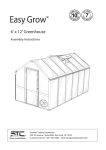
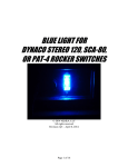
5
Gazebo GZ4 Monte Carlo
Aluminium Composite Roof Panels
6’8”
10’3”
Assembly Instructions
12’6”
4’6”
Systems Trading Corporation
450 7th Avenue Suite 2809, New York, NY 10123
Customer service: (877)782 4482 Email: [email protected]
www.stcny.com
1 of 24
Introduction
Thank you for purchasing the Gazebo GZ4.
When properly assembled and maintained, this gazebo will provide many years of enjoyment!
These instructions include helpful hints and important information needed to safely assemble and properly
maintain the gazebo. Please read these instructions completely before you begin.
Our patented gazebo has been designed for easy assembly. All steps can be completed by a team of
four people. The assembly should take about two hours.
Before Starting Assembly:
CAREFULLY READ ALL THE INSTRUCTIONS BEFORE YOU BEGIN AND FOLLOW THE
STEPS IN THE ORDER THEY ARE PRESENTED.
1.Make sure you have all the necessary parts:
Compare the contents of the four cartons to the List of Parts. If any parts are missing or damaged, or you have any questions, please contact Customer service: (877)782 4482 or by email at
[email protected] before beginning assembly.
2.Lay the parts out in separate staging areas:
The List of Parts has the corresponding step number referenced to each part. We recommend that
while you go through the list, make staging areas for each step and place the parts necessary for
each step in these areas. This will save you time and effort during assembly.
3.Select a Location:
When selecting a location for your gazebo, a flat level area is essential and if possible with proper water drainage and easy access to power and water, if neccessary.
Choose a sunny, level position away from overhanging trees and power lines and protected from the
wind as much as possible.Locate underground pipes or cables before preparing the site or anchoring
the gazebo.
Note: You may assemble the gazebo on a hard level surface and move it to its final location when finished. Make sure that there are no obstacles between the assembly area and the final position.
4. Prepare a Foundation:
After choosing a location, proper preparation of the site is recommended. The site must be level.
If the site is not level, create a base slightly larger than the outside dimensions of the gazebo using a perimeter of two by fours filled with either soil, sod or gravel.
Make sure the base is square by measuring the diagonals from both directions and making sure
they are equal. The gazebo is secured with pegs into holes cast with concrete.
If you decide to have a concrete base, it is best to contact a reliable contractor to make sure it is flat and level. Make sure you have checked with your local authorities regarding any required building permits.
5. Make sure you have the proper tools:
•
•
•
•
•
Tape Measure
Work Gloves
Safety goggles
Phillips Screwdriver
Spirit Level
•
•
•
•
•
2 Small Step Ladders
Wooden Mallet
Scissors
Liquid soap or WD40 Lubricant
Hex Key (included)
NOTE: A cordless drill with Phillips head bit is highly recommended but not essential.
www.stcny.com
2 of 24
Table of Contents
Safety Advice
Introduction................................................. 2
Table of Contents......................................... 3
List of Parts.................................................. 4
Step 1 Assembling the Corner Profiles................. 6
Step 2 Attaching the Rails to the Corner Profiles... 8
Step 3 Securing the Gazebo to the ground......... 11
Step 4 Installing the Lower Roof gable Profiles..12
Step 5 Assembling the Roof Top.............................. 13
Step 6 Connecting the Roof Top to the Roof
Gable Profiles.................................... 17
Step 7 Connecting the Horizontal Roof Profiles... 18
Step 8 Installing the Roof Panels and
Upper Roof Profiles.............................. 19
Step 9 Installing the Plastic Caps......................... 23
• The gazebo must be positioned and fixed
on a flat level surface.
• Dispose of all plastic bags safely. Keep
them out of the reach of children.
• Keep children and pets away from the
assembly area until the work is completed.
• Always wear shoes, gloves and safety
goggles when working.
• Take special care not to touch overhead
power lines with the aluminium profiles.
• Do not attempt to assemble the gazebo in
windy or wet conditions.
• Do not position your gazebo in an area
exposed to excessive wind.
• If using power tools or a ladder, always follow the manufacturers safety instructions.
• Hot items such as recently used grills,
blowtorches etc. must not be stored in the
gazebo.
• Make sure the gazebo complies with local
building codes.
General Order of Assembly
Step 1: Step 2:
Step 3:
Step 4:
Step 5:
Step 6:
Assembling the Corner profiles
Attaching the Rails to the Corner Profiles
Securing the gazebo to the ground
Installing the Lower Roof Gable Profiles
Assembling the Roof Top
Connecting the Roof Top to the Roof
Gable Profiles
Step 7 Connecting the Horizontal Roof Profiles
Step 8: Installing the Roof Panels and
Upper Roof Profiles
Step 9: Installing the Plastic Caps
ATTENTION:
DO NOT ATTEMPT TO
ASSEMBLE THE GAZEBO
ALONE!
5
6
7
4
2
8
9
1
1
3
www.stcny.com
3 of 24
List of Parts
The gazebo is shipped in four cartons. These cartons are heavy. Be careful when lifting them.
Wear proper safety gear including work shoes, gloves and goggles.
The parts are identified by removable stickers.
Place all the parts for each step in staging areas, checking that you have all parts as you go.
If any parts are missing or damaged, contact STC customer service before beginning assembly:
Customer service: (877)782 4482 Email: [email protected]
No.
1
Profile
Corner
Profile
2190mm
2
Qty Step
No.
8
1
10
8
2
11
8
5
12
Rail
3
Roof Top Profile
431mm
4
8
7
8
8
9
Roof
Gable Profile
945mm
Roof
Gable Profile
2102mm
black
side
Aluminium
Composite
Roof Panel #1
www.stcny.com
black
side
8
8
8
8
8
1
8
1
8
1
1
5
1
5
1
5
1
5
Support Plate
8
14
Roof Top Profile
2163mm
Roof
Gable Profile
431mm
Aluminium
Composite
Roof Panel #3
black
side
13
Roof Top Profile
933.9mm
6
Aluminium
Composite
Roof Panel #2
Qty Step
Support Frame
8
5
Profile
Roof Connector
8
5
15
Roof Top Cover
8
7
16
Hook
8
4
17
Tube
8
5
18
Washer
4 of 24
No.
Profile
Qty Step
No.
Profile
Qty Step
4,5
19
8
5
30
1
5
31
8
5
32
1
5
33
8
7
34
T-shaped Connector
24
5,9
2
2
1
We included some extra screws and bolts for your convenience.
Plastic Cap #2
2.5
72
7
Screw M6*12
2.5
96
6
Screw M6*18
48
1
Screw M6*25
www.stcny.com
3
Open Spanner
64
29
32
36
Outer Roof Connector
28
3
Ground Spike
8
27
32
1
35
Plastic Cap #1
26
5,8
Magnetic Hex Key
16
25
24
Concrete Bolt
Top Center Rail Connector
23
4,5
Screw ø4*8
Inner Roof Connector
22
24
Nut M6
Top Ring
21
8
Screw M6*38
Upper Roof Connector
20
88
5 of 24
STEP 1 Assembling the Corner Profiles
Place all the parts on a level surface.
Make sure the pieces are in the correct positions before assembling.
Carefully follow the order of assembly to ensure an easy installation.
Wear proper safety gear including work shoes, gloves and goggles.
Components
Corner profile (1)
Roof connector (14)
Support plate (13)
Support frame (12)
Screw (29)
x8
x8
x8
x8
x 48
1
1
ATTENTION: The corner profile (1) has two screw
holes to connect it to the roof connector (14)
and 8 pre-drilled screw holes to attach rails (2) in
step 2 at its top end.
It has four screw holes to connect it to the support
plate (13) at its bottom end.
Top end
1.A
Bottom end
Place all eight corner profiles (1) parallel to each other the ground. Attach one roof connector (14)
to each top end as shown and fasten with screws (29).
29
29
14
14
1
1
1
x8
14
www.stcny.com
6 of 24
1.B
Slide support frames (12) over lower end of corner profiles (1).
Attach support plates (13) to corner profiles as shown, using four screws (29) for each plate.
1
1
12
13
29
Leave support frames (12) about 10”over lower end of all eight corner profiles (1) until step 3
(Securing the gazebo to the ground)
1
12
13
13
12
1
www.stcny.com
x8
7 of 24
STEP 2 Attaching the Rails to the
Corner Profiles
Components
Rail (2)
Outer Roof Connector (25) Screw M6*12 (27)
2.A
x 16
x8
x8
Screw M6*18 (28) Plastic Cap #2 (26)
x 64
Magnetic Hex Key (34)
x1
x 64
Attach one outer roof connector (25) to each rail at pre-drilled screw holes, using screws (27).
27
25
25
2
VIEW FROM SIDE
25
2
VIEW FROM THE TOP
ATTENTION: Attach roof connectors
facing exactly in the directions shown.
x8
www.stcny.com
8 of 24
2.B
Attach one roof rail (2) to two corner profiles (1) as shown, using screws (28) and supplied magnetic hex key (34) through holes in profile set.
26
28
2
2
26
28
26
1
28
1
2.C
Close holes in profile set
with plastic caps #2 (26).
2
1
26
1
Repeat step 2.B and 2.C
to create four sets.
www.stcny.com
9 of 24
2.D
Using 4 people, attach roof profile (2) to
corner profiles (1).
Fasten with four screws (28) and supplied
magnetic hex key (34) on each side.
Close holes in profile sets with plastic
caps #2 (26).
2
28
26
1
2
2
1
1
1
1
ILLUSTRATION
2.E
Using 4 people, continue attaching roof
profiles (2) to corner profiles (1) to create
the octagonal gazebo base.
45°
45°
45°
90°
90°
45°
135°
IMPORTANT: After this step you
should place the gazebo frame in its
desired location.
All corners should be 135 degrees.
www.stcny.com
135°
10 of 24
STEP 3 Securing the Gazebo to the Ground
3.A
Fasten the gazebo frame to the ground, using four spikes (35) for each
support plate.
Lower support frames (12) to cover support plates (13).
Components
1
1
12
Ground spike (35)
x 32
35
13
13
Optional Securing the Gazebo to a Concrete Floor or Wood Deck
Components
Concrete Floor:
1. Using a concrete drill, drill holes into the concrete floor,
corresponding to the holes in support plates (13).
2. Insert concrete bolts (33) into the holes and hammer into place, using a mallet.
3. Fasten concrete bolts with washers and nuts.
1
Concrete bolts, washers and nuts (33)
x 32
1
1
33
33
33
Wood Deck:
1. Using an electric wood drill, drill holes into the wood floor,
corresponding to the holes in support plates (13).
2. Insert wood screws with washers (not supplied) into the holes and fasten,
using an electric screw driver.
x 32
NOT SUPPLIED
Wood Bolts, washers
to be purchased by user
x2
NOTE: After securing the gazebo to the
ground, we highly recommend filling the
corner profiles (1) with 2 bags (20LBs each)
of Pea Gravel each for extra stability,
as shown.
2
1
www.stcny.com
11 of 24
STEP 4 Installing the Lower Roof Gable Profiles
Towards center
BOTTOM VIEW OF PROFILE (8)
Towards outer edge
Components
ATTENTION:
DO NOT ATTEMPT TO
ASSEMBLE THIS ALONE !
4.A
Using screws (30) and nuts (31), connect roof
gable profiles (8) to roof connectors (14) on top
of all eight corner profiles (1).
Roof Gable Profile (8)
2102mm
x8
Screw (30)
x 16
ATTENTION:
Nut M6 (31)
x 16
Roof profiles, roof panels and
gables must be aligned properly during assembly to minimize any possibility of leaking.
ILLUSTRATION
31
30
www.stcny.com
12 of 24
STEP 5 Assembling the Roof Top
Components
Roof Gable Profile (6)
431mm
Roof Top Profile (3)
431mm
x8
Top Ring (20)
Upper Roof
Connector (19)
x1
x8
x8
Inner Roof
Connector (21)
x8
BLACK
SIDE
Top Center Rail
Connector (22)
Roof Top
Cover (15)
x1
Screw (30)
x 24
5.A
Hook (16)
x1
Nut M6 (31)
x8
Tube (17)
x1
Washer (18)
x1
Aluminium Composite
Roof Panel #1 (9)
x1
x8
Screw (28)
x 16
Screw (27)
Screw (32)
x 32
Plastic Cap #1 ׂ(24)
x 16
x8
Using screws (27), connect the eight upper roof
connectors (19) to the top ring (20) as shown.
27
19
27
5.B
Using screws (27), connect the eight inner roof connectors
(21) to the outside of top ring (20) as shown.
19
19
19
19
19
19
19
19
21
27
21
20
21
21
www.stcny.com
20
21
21
13 of 24
21
20
27
5.C
Using screws (30) and nuts (31), connect the eight roof gable
profiles (6), to upper roof connectors (19) as shown.
ATTENTION:
Roof profiles, roof panels and gables must be aligned properly during
assembly to minimize any possibility
of leaking.
31
30
19
6
20
6
6
6
6
19
19
6
6
19
19
19
6
5.D
19
20
6
Using screws (28), connect top center rail connector (22)
to roof gable profiles (6) as shown.
20
22
28
VIEW FROM BELOW
www.stcny.com
14 of 24
5.E
Insert hook (16) through hole in center rail connector (22) from below, through tube (17)
and washer (18) as shown.
Screw into roof top cover (15) from below.
15
18
17
22
16
5.F
Fit the eight roof panels (9) on top of roof profiles (6) with their black side towards the top
as shown and fasten each panel with two screws (32) from below at outer end.
IMPORTANT: Remove protective plastic from both sides of roof panels!
9
9
9
9
9
9
9
6
6
6
6
32
6
32
9
www.stcny.com
15 of 24
5.G
Place roof profiles (3) on top of roof profile (6). Align both profiles.
Fasten with two screws (30) from below.
3
6
3
Connecting the upper
and lower profiles
6
6
30
30
5.H
Close off roof profiles (6,3) with eight plastic caps #1 (24).
24
VIEW FROM BELOW
24
24
24
3
24
VIEW FROM TOP
www.stcny.com
16 of 24
STEP 6 Connecting the Roof Top to the
Roof Gable Profiles
ATTENTION: DO NOT ATTEMPT TO ASSEMBLE
THIS STEP ALONE, USE AT LEAST 4 PEOPLE!
Components
Screw (28)
x 16
6.A
Using screws (28) attach the roof top to roof profiles (8)
from below (inside the gazebo).
VIEW FROM BELOW
ILLUSTRATION
www.stcny.com
17 of 24
STEP 7 Connecting the Horizontal Roof Profiles
7.A
Attach T-connectors (23) to underside of roof gable profiles (8),
using screws (27) as shown.
Components
T-shaped Connector (23)
8
x8
Roof Profile (7)
8
23
23
23
8
x8
Screw (27)
x 24
23
8
8
23
27
8
VIEW FROM BELOW
7.B
Attach roof gable profiles (7) to T-connectors (23), placing ends into
cut-outs on gutter profiles (8) as shown.
Fasten from inside the gazebo, using screws (27) as shown.
7
7
23
7
8
7
7
7
23
23
7 VIEW FROM TOP
27
23
7
27
8
VIEW FROM BELOW
www.stcny.com
18 of 24
STEP 8 Installing the Roof Panels and Upper
Roof Profiles
IMPORTANT: Remove protective plastic from
both sides of roof panels. Place with black surface
toward the sun facing out when installing.
8.A
Fit roof panel (10) on top of roof profiles (8) as shown.
Components
BLACK
SIDE
BLACK
SIDE
Screw (32)
Aluminium Composite Aluminium Composite
Roof Panel (10)
Roof Panel (11)
x8
x8
x8
Roof Top Profile (4) Roof Top Profile (5)
x8
x8
Screw (30)
x 48
10
7
ATTENTION:
Roof profiles, roof panels and
gables must be aligned properly
during assembly to minimize any
possibility of leaking.
8.B
Fit roof panel (11) on top of roof
profiles (8) fasten with screw
(32) from below outer roof
connector (25).
10
11
8
11
25
8
32
VIEW FROM BELOW
www.stcny.com
19 of 24
8.C
Place roof top profile (4) on top of roof gable profile (7) as shown and fasten with two
screws (30) from below (inside gazebo).
Connecting the upper
and lower profiles
4
4
7
11
10
7
7
30
11
ILLUSTRATION
VIEW FROM BELOW
8.D
Fit second roof panel (10) on top of roof profiles (8) as shown.
Fit second roof panel (11) on top of roof profiles (8) as shown and fasten with screw (32)
from below to outer roof connector (25).
10
10
11
11
8
11
25
8
11
32
VIEW FROM BELOW
ILLUSTRATION
www.stcny.com
20 of 24
8.E
Place second roof top profile (4) on top of roof gable profile (7) as shown and fasten with two
screws (30) from below (inside gazebo).
7
7
10
10
4
30
11
11
11
11
VIEW FROM BELOW
ILLUSTRATION
8.F
Place roof top profile (5) on top of roof gable profile (8), aligning the profiles at their outer end.
Fasten with four screws (30) from below (inside gazebo).
10
8
10
11
11
5
11
VIEW FROM BELOW
11
ILLUSTRATION
www.stcny.com
30
21 of 24
8.G
Continue steps 8A through 8F in a clock-wise direction as shown, until the last two panels:
Place the upper roof panel (10), secure with two screws (32) from below.
Place the lower roof panel (11), secure with three screws (32) from below.
Place the horizontal roof top profile (4), fasten with two screws (30) from below.
Place the top roof gable profile (5), fasten with four screws (30) from below.
VIEW FROM TOP
11
11
11
10
10
11
10
10
10
11
10
10
11
11
8.H
Place the upper roof panel (10), secure with two screws (32) from below.
Place the last two top roof gable profiles (5) on top of roof gable profiles (8), align
and fasten ONLY AT THE TOP ENDS with 1 screw (30) from below.
5
10
5
ILLUSTRATION
www.stcny.com
22 of 24
8.I
Slightly lifting the roof gable profiles (5), place the lower roof panel (11) and secure with three screws
(32) from below.
Fasten the roof gable profiles (5) at their lower end with screws (30) from below.
Place the horizontal roof profile (4) carefully from above as shown, fasten with two
screws (30) from below.
4
ILLUSTRATION
STEP 9 Installing the Plastic Caps
9
Components
Close off roof profiles (5,8) with plastic caps #1 (24).
Plastic Cap #1 (24)
x8
5,8
24
VIEW FROM TOP
ENJOY YOUR
COMPLETED GAZEBO !
www.stcny.com
23 of 24
Gazebo GZ4 Monte Carlo
Aluminium Composite Roof Panels
Assembly Instructions
WARRANTY: Warranty covers damage due to manufacturing defects only.
Warranty does not cover weather inflicted damage (Force Majeure) and/or
damages caused by not following assembly instructions and not adhering to
warnings in manual.
EasyGrow
Visit: http://www.stcny.com
for more Lawn and Garden products
8’x 12’ Greenhouse
Systems Trading Corporation
450 7th Avenue Suite 2809, New York, NY 10123
Customer service: (877)782 4482 Email: [email protected]
www.stcny.com
24 of 24