Download INSTALLATION MANUAL
Transcript
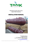
Glasteel Tanks
(Fibreglass Wrapped Steel)
INSTALLATION MANUAL
Tank Solutions Pty Ltd
513 Tomago Road, TOMAGO NSW 2322
PO Box 623, RAYMOND TERRACE NSW 2324
Ph: + 61 2 4964 8270
e-mail [email protected]
Form: F 940
Revision D
Page 1 of 4
1.
INTRODUCTION
1.0
Proper installation is essential to the expected product life and performance of a Tank Solutions Glasteel II Underground
Storage Tank. This tank must be installed in accordance with these installation instructions, the latest AS4897-2008 and
APICSA recommended practices and authorities who have jurisdiction over underground tank installations and codes.
1.1
Failure to follow these instructions will void the tank warranty and may cause tank failure, serious personal injury or
property damage. Since Tank Solutions does not control the parameters of any installation, our sole responsibility in any
installation is that presented in our warranty.
2.
TANK HANDLING
2.0
Caution shall be used when handling the tank. Do not roll or drop the tank.
2.1
Equipment to lift and lower the tank shall be of sufficient capacity to do so without dragging or dropping the tank.
2.2
The tank shall be lifted and lowered using the lifting lugs provided. Cables or chains used shall be of adequate length. No
circumstances warrant the use of chains or slings around the tank shell.
3.
TANK STORAGE
3.0
If the tank is stored on site prior to installation, a secure area shall be chosen. Special attention shall be placed in
selecting the storage location to ensure the absence of rocks and foreign objects that might cause damage to the tanks
outer jacket.
4.
INPSECTION
4.0
Visually inspect the tank exterior for damage. Serious gouging or abrasion should be carefully reviewed and appropriate
action taken. Refer to Tank Solutions if there is any doubt as to the remedial action required.
4.1
Remove thread protectors and shipping plugs from all openings (except vacuum gauge location). Using compatible, non
hardening pipe sealant, install permanent metal plugs in all unused openings.
5.
PRE INSTALLATION CHECKS
5.0
Tank Solutions tanks are tested prior to shipment, but the tank must be checked at the site prior to installation. The
Installer is responsible for verifying vacuum gauge reading on the annular space by opening the needle valve. If a
minimum of 17kPa of vacuum is maintained for one hour, the interstitial space may be considered properly tested.
CAUTION: Do NOT Pressure Test the Interstitial Space.
6.
EXCAVATION AND BEDDING
6.0
The installing contractor must take all precautions necessary to protect employees working in or near a tank excavation.
These precautions should include, but are not limited to:
•
Location and protection of any utility installations near the excavation before opening the excavation;
•
Means of securing the walls of the excavation;
•
Means of preventing exposure of employees to hazardous fumes from the excavation;
•
Protection of employees from hazards associated with water accumulation in the excavation;
•
Barricades, etc. to prevent unauthorised vehicle or pedestrian traffic;
•
Inspection of the excavation and surrounding area at least daily.
6.1
Glasteel II underground storage tanks are designed to withstand a maximum burial depth of 2.1 metres. If a greater burial
depth is required, contact the manufacturer immediately.
6.2
The bottom of the excavation shall be suitably graded and levelled. The foundation for the tank shall be suitably graded
and have a minimum of 300mm of approved backfill (refer to Section 8). The tank shall be encompassed by approved
backfill, free from foreign matter which could cause damage to the tank exterior.
6.3
Soil Conditions
Stable Soil Conditions – Where shoring is not required to maintain a vertical wall from top to bottom of the excavation,
there shall be a minimum of 450mm (600mm for 3.5m tanks) from the outside edge of the tank to the inside edge of the
excavation. This distance shall remain true for the entire perimeter surrounding the tank.
Unstable Soil Conditions – Where soil will not maintain a vertical wall, the excavation must allow a minimum space equal
to ½ the diameter of the tank between the side and end cap of the tank and the excavation wall. Spacing between
adjacent tanks to be a minimum of 450mm.
NOTE: These are minimum spacings and must be increased as needed to accommodate anchors or anchor slabs. Always
allow sufficient clearance to allow the anchors to be set outside of the tank shadow. The relevant Australian Standard
(AS1940) specifies the minimum tank separation distances.
Form: F 940
Revision D
Page 2 of 4
7.
ANCHORING
7.0
Tank Solutions recommends the use of properly designed anchor straps to overcome existing buoyant forces. The straps
are used in conjunction with a concrete hold-down slab or concrete anchors.
CAUTION: Use of steel cable or round bar is prohibited.
7.1
An approved Polyester Webbing Strap and Binder system is recommended. Do not over tighten hold-down straps beyond
snug to tank surface and do not re-tighten straps after ballasting.
7.2
Strap location guides are marked on the tank and should be followed.
7.3
Concrete anchors are reinforced concrete beams with a total length 300mm greater than the overall length of the tank. A
concrete anchor may be fabricated in multiple sections as long as the total length is not decreased and each section
contains at least two anchor points. The width and thickness depend on the tank diameter.
TANK SOLUTIONS recommends anchors 300mm deep x 300mm wide and 300mm longer than the overall dimension of
the tank for 2190mm and 2750mm diameter tanks. For 3460mm diameter tanks, concrete anchors should be 300mm
deep x 450mm wide and 300mm longer than the overall length of the tank.
NOTE: Bottom anchoring is the only acceptable method of anchoring. Pea gravel/crushed stone is Tank Solutions
preferred backfill material. NOTE: A fibre-glassing kit is shipped with the tank and provides materials to cover external
attachments, such as the lifting lug covers. All finishing work will be done prior to backfilling. Before attaching lifting lug
covers, the area should be lightly hand sanded to create a suitable bonding surface.
NOTE: Lift lug covers MUST be fitted to provide corrosion protection of primary tank.
8.
BACKFILL
8.0
Tank Solutions recommends that tanks be installed using either crushed stone or pea gravel which meets the following
specifications:
•
Backfill material must be self compacting, washed and free flowing
•
Material must conform to the specification of AS2758 and AS1141
•
No more than 5% (by weight) of the material may pass through a 2.36mm sieve.
•
It is recommended that the supplier certify that the material conforms to AS2758 and any other applicable
specifications.
(For more information, refer to the Tank Solutions Backfill Guidelines)
NOTE: If material which does note meet these specifications is not available, contact Tank Solutions for information on
approved alternate materials such as compacted cleaned washed river sand. Do not use native soil as backfill material.
All excavated native soil must be replaced with an approved material. Using other than the approved bedding and backfill
materials without Tank Solutions’ prior written approval will void the tank warranty and may result in tank failure.
8.1
Compact bedding and backfill materials to ensure adequate support of the tank. To prevent voids, deflection and to achieve
the correct degree of compaction, all the backfill materials should be carefully and properly placed under the lower quadrant
of the tank before ballasting. THIS COMMENT OFTEN BEGS THE QUESTION “ WHAT LEVEL OF COMPACTIION IS
REQUIRED?”
NOTE: Do not backfill in layers using different materials.
8.2
After backfill is placed to the top level of the tank, it is recommended that ballast be added until the piping and installation is
complete. Never allow ballast to be at a higher level than the surrounding backfill.
If the tank must be water ballasted during the backfill procedure, use only potable water. Ballast water shall not remain in the
tank for longer than 60 days. If product is used as ballast, proper precautions must be taken to prevent fires, spills, leaks,
and other associated accidents. Monitor product level frequently to ensure there has been no loss of product.
Tank Solutions does not recommend the use of product as ballast.
8.3
Tanks installed in areas that will be subjected to vehicular traffic shall be protected to: Minimum 450mm of backfill plus
150mm of reinforced concrete or 200mm of asphalt paving.
8.4
Tanks subjected to traffic loads and high water must have a minimum of 760mm of backfill and either 230mm of asphalt or
150mm of reinforced concrete and must be anchored.
8.5
Tanks not subjected to traffic loads must have a minimum cover depth of 600mm of backfill or 300mm of backfill plus 100mm
of reinforced concrete or 150mm of asphalt.
8.6
Tanks in high water areas not subjected to traffic loads must have a minimum of 920mm of backfill covering and must be
anchored. WARNING: In a non-traffic installation, ensure that the areas above the tanks will neve be subjected to
traffic loads.
Form: F 940
Revision D
Page 3 of 4
NOTE:
•
•
•
•
These depths are a MINIMUM in all cases
Asphalt and concrete pads must extend a minimum of 300mm beyond the tank in all directions
Maximum burial depth is 2.1m of cover over the top of the tank
Manway riser (if present) must not transmit load from the slab to the tank. There must be a minimum 150mm space
between the bottom of the concrete pad and the top of the riser.
9.
FINISHING INSTRUCTIONS
9.0
Glasteel II tanks will be shipped with a factory set vacuum. There are two layouts for vacuum monitoring equipment
depending on the type of tank. Tanks which have a manway and riser will have the vacuum monitoring gauge positioned in
the collar. These require no additional work during the installation process. Tanks which are direct buried are supplied
with the vacuum monitoring gauge and hose fitted, and temporarily located in a PVC pipe attached to the tank to protect
the assembly during transport. The protection should be removed from the tank and a replacement pipe installed to bring
the gauge assembly to ground level.
Install and seal the lifting lug covers.
10.
POST INSTALLATION TESTING
10.0
After backfilling to grade, monitor and level of vacuum again to ensure no damage has been done to the tank during the
installation process. If a minimum of 17kPa of vacuum is maintained for at least one hour, the interstitial space may be
considered properly tested.
WARNING: Do not use air pressure to test tanks that contain flammable or combustible liquids or vapours. The fuel/air
mixture may explode and cause death, sever personal injury or property damage. Tanks that will be ballasted with a
flammable product should be air tested before ballasting.
WARNING: If product is used as ballast, exercise special care in handling. Safeguard against sparks, fire or product
spills. Improper handling of product can cause a fire or explosion and may result in death, severe personal injury or
property damage.
The tank may be ballasted after the backfill is even with the top of the tank and post installation testing has been
successfully completed.
CAUTION: Do NOT pressure test the interstitial space.
11.
TANK WARRATY ACTIVIATION
11.0
For Glasteel II warranty to be initiated, the Installation Checklist MUST be properly filled out by the customer and returned
to Tank Solutions. The Installation Checklist must be returned within 30days after the date of installation.
11.1
If the tank has not been installed within 90 days of delivery from the manufacturer, it is required that the tank be re-certified
by the manufacturer, at the owners expense, prior to installation.
12.
MAINTENANCE
12.0
Maintenance of Underground Storage Tanks. The primary tank should be inspected monthly for the present of water.
Inspections should take place at the lowest possible points inside the primary tank. Remove any water found. Tank
Solutions recommends that all types of fuel storage tanks, regardless of materials used for construction, be subjected to
regular scheduled maintenance for the detection and removal of water.
Form: F 940
Revision D
Page 4 of 4


