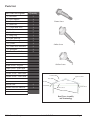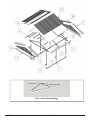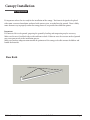
1
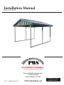
Installation Manual
10’W x 12’L x 6.5’H
Premium Canopys
Protective Weather Structures Inc.
5290 Orcutt Road
San Luis Obispo, CA 93401
© 2011 - All Rights Reserved
PWSsteelbuildings.com
Customer Service
1-888-547-8797
PWS has dedicated years of steel building knowledge and construction to creating the highest quality canopy made today.
With a little effort following the detailed instructions during assembly, this canopy will provide you with years of enjoyment and
unparalleled protection.
Contents
Safety & Hazards Consideration................................4
Tools Required..............................................................4
Parts List........................................................................4
Canopy Installation.................................................................... 6
Site Preparation.......................................................................... 6
Foundation & Anchoring.......................................................... 7
Erecting Frame............................................................................ 8
Insulation................................................................................... 10
Eve Trim.................................................................................... 11
Roof Sheet.................................................................................. 12
Gable ......................................................................................... 13
Rake Trim.................................................................................. 14
Ridge Trim................................................................................. 15
PWS - Premier Canopies
1-888-547-8797
Page 2
Safety & Hazards Considerations
•
•
•
•
•
•
•
•
•
•
•
•
•
Check that all tools and canopy components are available prior to erecting structure.
Two people are necessary to safely erect the canopy.
Do not allow children to play around the assembly area.
Protect yourself by wearing protective work gloves, hard hat, safety glasses, and shoes during assembly.
Some parts have sharp edges which may cause cuts or lacerations.
Do not attempt to assemble canopy on a windy day as wind may create both difficulty assembling canopy,
possible injury as well as damage to the structure.
Do not attempt to assemble the canopy during wet weather, which may cause slipping off the roof.
Keep in mind that the metal components may get hot on a sunny day. Protect your skin from touching
the hot components.
Keep canopy away from electrical sources such as overhead power lines and underground cables during
assembly. Serious injury or death may occur if contact is made with a live power source.
Do not attempt to assemble the canopy if tired, have taken medication, drugs, or alcohol.
Adhere to manufactures safety advice for all tools and equipment used to erect the canopy.
Consult with local planning and building authorities prior to constructing canopy.
Do not install canopy in areas with snow and wind loads greater than the canopy’s rating.
Protect the canopy finish by assembling the components on a soft platform to prevent scratching and
damage.
Tools Required
•
•
•
•
•
•
•
•
•
•
•
•
•
•
Safety Goggle or Glasses
Work Gloves
Tape Measure (30 foot preferable)
Level
Framing Square
8lb+ hammer
Utility Knife
Pencil/Marker
Hammer Drill (for existing concrete slab anchors only)
Masonry Drill Bit – ½” x 8” Drill Depth (for existing concrete slab anchors only)
Electric Screw Gun with Adjustable Torque Setting
5/16” Socket Drive (supplied)
Socket Drive Extension
Two 8’ Step Ladders
PWS -Premier Canopies
1-888-547-8797
Page 3
Parts List
Part # and Description
( 1 ) Base Rails
( 2 ) End Columns
( 3 ) Center Columns
( 4 ) Roof Truss
( 5 ) Center Roof Truss
( 6 ) Purlins
( 7 ) Eve Trim
( 8 ) Ridge Cap
( 9 ) Rake Trim Left
( 10 ) Rake Trim right
( 11 ) J-Trim
( 12 ) Gable Sheet Metal Kits
( 13 ) Insulation
( 14 ) Roof Sheet Metal
Quantity
2
4
2
2
1
6
5
1
2
2
4
6
3
8
Frame Screw
Sinker Screw
Stitcher Screw
Frame Screws – Regular
Sinker Screws – Roof Color
Sinker Screws – Trim Color
Stitcher Screws – Roof Color
Stitcher Screws – Trim Color
Left Truss Half
Right Truss Half
Truss Rafter
Eve End
Anchor Stake
Double Sided Self Adhesive
6
1
Truss Face
Truss Cord
Column Insert
Columns
Roof Truss Assembly
and Terminology
PWS - Premier Canopies
1-888-547-8797
Page 4
Column Inserts
Base rail and Terminology
PWS -Premier Canopies
1-888-547-8797
Page 5
Canopy Installation
Site Preparation
It’s important to have the site ready for the installation of the canopy. The frame is designed to be placed
either onto a concrete foundation, anchored with concrete piers, or staked into the ground. There is likely
more than one way to properly anchor the canopy, however, we provide three different options.
Important:
If a concrete slab is to be poured, preparing the ground by leveling and compacting may be necessary.
Make sure the area is level both side to side and front to back. Failure to erect the structure on level ground
may cause poor results in the installation process.
Make sure you have adequate room around the perimeter of the canopy to be able to move the ladders and
handle the materials.
Base Rails
Column inserts
PWS - Premier Canopies
1-888-547-8797
Page 6
Foundation &
Anchoring
Option 1: Direct Staking
The canopy is delivered with rebar stakes that can be used to
either directly stake the canopy down into firm ground or in
option 2 page 8 as an anchor for concrete piers.
The Simplest method to anchor the canopy is to pound the
supplied stakes into the ground with a hammer after the base
rails are properly spaced. (See Positioning Base Rails below.)
Note:
Anchoring the rebar stakes into the ground best serves as a
temporary anchoring solution.
In areas where there are high wind loads, we highly
recommend using permanent anchors to hold down the
canopy as in Option 2 or 3. (See page 8.)
10’-0”
Positioning Base Rails
It’s critical that the base rails are properly oriented
when anchored.
11
/1
15
’-3
”
6
1/1
31
15
Ensure that the base rails are the proper width apart,
lying flat and parallel to each other. Check by having
the diagonal measurements equaling the same, from
inside corner to inside corner, approximately
(15’-3 11/16”). If the diagonal measurements are not
the same, then the base rails are not square and must
be corrected (fig 1).
6”
Failure to properly install the base rails will
cause the rest of the installation to be difficult, or
impossible.
(fig 1)
PWS -Premier Canopies
1-888-547-8797
Page 7
Option 2 : Anchor to New Concrete Pier
The second simplest method to anchor the canopy frame is to pour concrete piers. Layout the base rails per
the previous instruction (see Positioning Base Rails page 7) and mark the locations where the Anchor Stake
are to be located. Remove the base rails and dig
each hole a minimum of 24” or down to the
frost line, whichever is greater (fig 2).
Once the holes are dug, fill with concrete,
replace the base rails over the holes and make
the necessary measurements to ensure proper
placement. Insert the supplied rebar stakes into
the wet concrete. Double check the measurements to ensure that the base rails are in the
proper position. Concrete should cure for 24
hours before canopy assembly.
(fig 2)
Option 3 : Anchor to Existing
Concrete Slab
If you already have a level concrete slab, you have the option of using wedge anchors (not provided) to
anchor directly to the concrete slab. Layout the base rails per the previous instruction and mark the locations
where the anchors are to be located. Using the hammer drill and 1/2” x 8” concrete bit, drill a minimum of
3 1/2” into the concrete slab for each anchor location (photo 1). Be aware that the vibration from the drill
could move the base rail, be sure to double check that it is in the proper location prior to drilling the next
hole. Once the holes are drilled, verify that they are deep enough before installing the wedge anchors (fig 3).
Follow the anchors installation instructions. Be mindful not to overtighten the bolt and crush the base rail.
tube.
1/2”x 5x1/2”
6” Wedge Anchor
1/2”
Base rail
3” Minimum Embedment
(photo 1)
(fig3)
PWS - Premier Canopies
1-888-547-8797
Page 8
Canopy Frame Assembly
Roof Truss Rafter
Eve end
Eve Face
Column Inserts
Truss Assembly
Step 1 - Verify the placement of the Base rail assemblys for
squareness and correct rail separation.
Tip: Laying the truss components at least 8 feet in front of the
Base rails will help simplify the ease of assembly.
Step 2 - In preparation for assembly, stack all the trusses. Using
dimensions in (fig 4, page 10) measure from the eve end
moving to ridge, mark the purlin locations using a square and
marker (photo 6).
(photo 6)
PWS -Premier Canopies
1-888-547-8797
Page 9
64”
32”
3/4”
(fig 4)
Step 4 - Install the columns to the rafter by slipping them over the
column inserts. Check that the columns are at right angles to the
rafter by using a framing square as shown (photo 8).
You can verify that the columns are square by measuring the distance
at the bottom of the columns. This distance should be the same as the
width of the frame (10 feet apart). Attach all columns as shown (fig
6). Each leg requires 4 frame screws.
(photo 8)
Note: It is best to complete and raise one frame at a time. When rais-
ing Roof Truss Assemblie , two people are necessary to lift the rafter
and column assembly to place it. Face the screw heads towards the
inside of canopy on both end rafters. Face screws to the back on the
center frames.
Step 5 - Begin installing rafter assembly at the farthest point on the
base rails. Rest the end of the column against base rail column insert
(photo 9). Now raise Roof Truss Assembly and place onto base rail
column insert. Repeat Steps 2-4 for the center and end trusses. Sight
down the bottoms of all the eves next to the columns to confirm that
they are even. If adjustments to a low eve are required, lift the column as needed. Raise the truss eve so it is even with the others, then
C
secure the columns
to the base rail with 4 frame screws (fig 7).
(photo 9)
2”
5"
1
2"
5”
5"
1
2"
2"
2"
Attach to Base Rail Detail
(fig 7)
PWS - Premier Canopies
Left: End Rafter
Right: Center Rafter
(fig 6)
1-888-547-8797
DETAIL B
DETAIL C
SCALE 1 : 10
Page 10
Purlin Assembly
Purlins
Purlins
Assembled Frame
(photo 12)
Step 1 - The purlins should be with the large holes facing up
laying tight next to base rails. Line up the ends of the assembled purlins with the ends of the base rails. Mark next to the
holes at the edges of each column (photo 12).
Note: Installing purlins
(photo 13)
It is recommended that you start from the top, working your
way down. It is very important that the purlins are installed
in the proper locations or else other components such as eve
trim and light brackets may not fit. Please verify that everything is correct before the purlins are installed.
If a mistake is made, the only solution will be to move the
purlins into the correct location.
Step 3 - Screw through the purlin hole and into the rafter
using frame screws (photo 13). The purlins should be aligned
using the marks made in the Truss Assembly step 2 and step 6
on page 9 as guides. The holes should be centered to the rafter
as well as the purlin being flush with the outside face of the
end rafter (photo 14). It may take some effort to position the
rafters appropriately so that all the purlin locations line up.
(photo 14)
PWS -Premier Canopies
1-888-547-8797
Page 11
Insulation
Insulation
Note: It is not recommended to install the Insulation on a
windy or breezy day as the adhesive will not likely hold in these
conditions.
Step 1 - Apply the double sided adhesive tape on top of both
(photo 16)
the outermost purlins from end to end as shown, leaving the
tape cover on for now (photo 16).
Step 2 - Place the first of 3 sheets of insulation over the
canopy, white side facing down. The insulation will be several inches longer than need be on both sides. This is normal
and will be trimmed in a later step. The insulation also has a
strip of self-adhesive tape, on the first sheet of insulation this
will be used to assist in securing the insulation to the purlins
towards the end of the canopy. At this time remove the tape
cover on both the purlins as well as the insulation. With two
people holding the insulation, pull it tight and square with
the frame, pressing down firmly onto the self-adhesive tape to
ensure that the insulation is securely placed (photo 17).
Step 3 - Using a utility knife, trim the excess insulation flush
with the outmost purlins as shown (photo 18).
Step 4 - Follow same procedure as in step 2 with each sheet
(photo 17)
PWS - Premier Canopies
of insulation noting that the self-adhesive on the insulation
will be used to adhere to the previous sheet of insulation
where they overlap. Trim excess insulation as in step 3.
Note: Overlap the previous sheet so the last sheet’s edge lays
even at the end face of the rafter (photo 19).
1-888-547-8797
Page 12
(photo 18)
(photo 19)
Eve Trim
Eve trim
Step 1 - Begin installing the first Eve trim at the back of
canopy frame working forward. Place trim on top of
Insulation and end of rafter with drip edge down. Extend it
past outside of rafter face 11/4” (photo 20)(fig 8 on page 14).
Note: It’s very important to press down firmly to compress
the insulation before fastening it down. Otherwise, when the
roof sheet is installed, it will tend to cause it to deform.
Step 2 - Measuring from the bottom of the eve 11/4”, fasten
the eve trim to the rafter ends with matching color sinking
screw (photo 21). Leave the last rafter screw out so the front
trim can overlap at the middle. Continue to the front trim
holding 11/4” from face of rafter. Attach at each rafter end and
repeat step 1 and 2 on opposite side (photo 21).
(photo 20)
(photo 21)
PWS -Premier Canopies
1-888-547-8797
Page 13
Roof Sheet
Roof sheeting
Truss face
Warning - Do not attempt to stand on roof panels that
have not been attached.
Step 1 - The placement of the first sheet is the most critical.
J
(photo 22)
The sheet is not symmetrical and must be started as shown
(photo 22) with the short overlap facing out. Make sure the
sheet is square to the frame. It must be positioned a set disI
tance from the face of the rafter as well as from
the eve trim
(fig 8)(fig 9). Use your square to verify these measurements
(photo 23).
• Overhang from the Truss face: 11/4” (fig 8)
• Overhang from eve trim face: 21/2” (fig 9)
Note: These overhangs are critical. If the overhang
(photo 23)
measurements are not followed, the rake trim will not fit
properly. The overhang from the truss face is necessary for the
roof sheets to space out properly, and the overhang from the
eve trim is required because the rake trim is pre-cut for this
overhang (photo 24).
1
14"
1
22"
(photo 24)
PWS - Premier Canopies
Left: Side View
(fig 9)
Right: Front View
(fig 8)
DETAIL J
SCALE 1 : 10
1-888-547-8797
DETAIL I
SCALE 1 : 10
Page 14
Note: Double check the 21/2” overhang and make sure the
sheet is perpendicular to the purlins. The stitcher screws are
only used to fasten sheet metal to sheet metal. Make sure the
screws are the correct type and color.
Step 2 - Follow the pattern below to fasten the sheet to the
purlins (fig 9). Mark the location by measuring out where
the screws go before lifting sheet onto the roof (photo 25). It
is recommended that one individual is on the roof who will
fasten the sheet with screws, while another individual makes
sure the sheet is positioned correctly (photo 26). It will take 8
sheets per side with the last sheet overlapping the previous, by
one third.
Stitcher Screws
1
68 2 "
Sinker Screws
67”
1
36 2 "
(photo 25)
3
34"
35”
Screw Pattern - Roof (fig )
PWS -Premier Canopies
(photo 26)
1-888-547-8797
Page 15
Gable and J-trim
Gable kit
J-trim
Step 1 - Align the bottom of the J-trim with the bottom of
the truss cord and extend end of J-trim to eve trim
(photo 27). Using frame screws, fasten the J-trim to the face
of the truss in from each end 2”. These screws will be removed
later. Repeat this step on the other end.
Step 2 - The Gable kit comes in five pre-cut pieces per end.
(photo 27)
(photo 28)
Start with the center left section (photo 28).
Use a level to verify that the ribs on the sheet metal are indeed
vertical before fastening with the same color screws. The sheet
metal should sit down into the bottom of the J-trim. Check
that J-trim is even with bottom of rafter cord, as well as relatively flush with the top edges of the rafter before attaching.
Note : Each sheet to the left of the center will slip under the
previous sheet. Sheets to the right of center will over lap the
previous sheet. Due to variations in cutting, the sheets may be
somewhat irregular, however this irregularity will be covered
by the rake trim. Just as in the roof sheet metal, use stitcher
screws on the high ribs where it is a sheet metal to sheet
metal. Use sinker screws where you screw into the rafter. The
diagram on page 17 shows where to fasten the gable pieces
(fig 10).
In order to hide the bottom screws, try to screw down as
low as possible in the J-trim without marring its paint finish
(photo 29). Make sure the screws are down far enough so that
they are going into the cord of the rafter, a bit driver extension
will make this easier to do.
Step 3 - Repeat steps 1 & 2 for the other end of canopy.
(photo 29)
PWS - Premier Canopies
1-888-547-8797
Page 16
Sinker Screws
Screw Pattern - End Gables
(fig 10)
Stitcher
Screws
Sinker Screws
Rake Trim
Rake trim
Step 1 - Locate the left side, uncut Rake trim, and position it
as shown in (photo 30). If the roof sheet was fastened in the
correct location, the top edge should line up directly in the
middle of the peak, and the bottom edge should line up with
the roof sheet. If it does not align properly, the only solution
would be to move the roof, if the rake trim is too short, or cut
the top of the rake trim if it’s too long.
(photo 30)
Step 2 - Before fastening the rake trim to the roof sheet and
end gable, check to make sure the trim’s shape is square itself
and square to the sheet. This can be done several ways, one
method is to use a framing square. Another way is to use a
level, (photo 31). However, the accuracy of this method is
directly related to how level the ground is that the canopy is
built upon.
(photo 31)
PWS -Premier Canopies
1-888-547-8797
Page 17
(photo 32)
(photo 33)
Step 3 - Using the same color stitcher screws as the
(photo 34)
trim, the first screw should be into the face of the J-trim
drilling through the edge of the rake trim as shown in
(photo 32) and (photo 33). After verifying that everything is square and in place, fasten a sinker screw down
through top edge of the rake trim and down through the
roof sheet into the center of the purlin below. Continue
on every purlin. You will want to make sure you have the
location of the purlin correct before drilling each screw.
Up the outside of the rake trim, use stitcher screws to attach to the high ribs of the end gable sheet metal. Match
near the screws location in the purlins. At this time, do
not attach a screw at the peak. However, you can drill the
remaining sinker screw through the top purlin where the
rake trim pieces come together (photo 34).
Step 4 - Just as the left piece, make sure it is square and
(photo 35)
straight before attaching. The right side rake trim piece
is cut such that it makes a vertical seam in the front for
aesthetics (photo 35). The top flap is meant to fold over the
left piece, making it such that water can’t get in as easily. It
may be necessary to manipulate the flap so that it fits well.
Attach the right trim piece according to the same instructions in previous steps 1 through 3.
Step 5 - The last stitcher screw goes through both rake
trim pieces and into the middle high rib of the end gable
sheet (photo 36). Each rake piece should have a total of 8
screws holding it down.
Step 6 - Repeat steps 1 through 5 for the other end of the
canopy.
(photo 36)
PWS - Premier Canopies
1-888-547-8797
Page 18
Ridge Cap
Ridge Cap
Note : The ridge cap attaches in two pieces. Be careful
while handling, they can buckle which will leave an
undesirable crease.
Step 1 - Begin by laying the first ridge cap starting from
the back. Align the ridge cap end even with the outside face
of the rake trim (photo 37). Using color matched stitcher
screws, attach through the edges of the ridge cap into the
rake trim on both sides. Align the other end of the ridge
cap with the center of roof ridge. Do not attach at this time.
Step 2 - Repeat step 1 for the front trim, overlapping the
(photo 37)
back ridge in the middle. Now attach to the top ribs of the
roof sheet metal through both ridge edges at the overlap.
Continue to attach at the high ribs of the roof about every
4 feet. In total you should have used 14 screws.
PWS -Premier Canopies
1-888-547-8797
Page 19
PWS - Premier Canopies
1-888-547-8797
Page 20