1
ASSEMBLY INSTRUCTIONS
Item # 00175 or
#50175-10
60" x 45" Ceiling Mounted Shelf
MISSING A PART?
There is no need to
return this item to the
store. Instead call our
TOLL FREE HOTLINE.
Joists
24" to 32"
apart
I
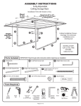
Parts Included:
IMPORTANT-Read through entire instructions before beginning any installation.
4-Downrods
4-Wire Grids
15" x 45"
2-Support Bars
8-Lag Screws 5/16" X 2 ½"
4-Carriage Bolts 6-32 x 2"
8-Carriage Bolts ¼" x 2"
4-Washers
6-32
4-Hex Nuts
6-32
4-Corner rods
16-Hex Bolts ¼" x 1½"
24-Hex Nuts Serrated ¼"
Tools Required:
Eye Protection
OR
3/16"
Drill Bit
(4.8mm)
Power
Drill
7/16" Wrench
(11 mm)
7/16"(11 mm)
Socket Wrench
or Nut Driver
Stud/Joist
Finder
(optional)
Framing
Square
(optional)
Pencil
Tape Measure
Ladder or
Step Stool
IMPORTANT-READ THROUGH ENTIRE INSTRUCTIONS BEFORE BEGINNING INSTALLATION
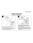
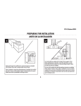
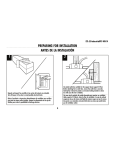
Locate the ceiling joists in the area of desired installation and determine the direction in which they are
running. The ceiling mounting plates on Downrods(B) are installed parallel to the ceiling joists. Refer to
the diagram below for additional installation clarification.
INSTALL DOWNRODS
Outside edge of
Downrod footplates
must measure
exactly 69" apart
Using Stud/Joist finder
locate any 2 Joists
24" to 32”
apart
Ceiling Joist
Place Downrod (B) against ceiling under joist location and mark holes
running parallel with the joist. Pre-drill each hole location using a 3/16" drill
bit. Install Downrod (B) using 7/16" Socket Wrench or Nut Driver and two (2)
¼ x 3" Lag Screws (E).
From the outside edge of the Downrod (B) footplate just installed, measure
69" inches along ceiling joist and mark this location. This mark will be the
OUTSIDE edge of the second Downrod (B).
Install second Downrod (B) and make sure it lines up with the first Downrod
(B) installed on the joist.
Repeat to install the remaining two (2) Downrods on a joist which can vary
from 24" to 32" apart from the 1st joist.
IMPORTANT:
Downrods must be mounted perfectly in line and square to each other.
INSTALL CORNER RODS & SUPPORT BARS
I
I
C
D
I
Attach two (2) Corner Rods (C) to each of the Support Bars (D) using four (4) ¼” x 1½“ Hex Bolts (I) and four (4) ¼”
serrated nuts (K).
Determine the length down from the ceiling you want the unit to hang. (from 32” to 40” )
Attach the Corner Rod (B) and Support Arm (C) assembly to each Downrod (B) at the predetermined length using two
(2) ¼” x 1½” Hex Bolts (I) and two (2) ¼” serrated hex nuts(I) for each. Repeat Step 2 for the other set of Downrods (B).
INSTALL GRIDS
J
Quad
wires
Quad
wires
Quad
wires
J
Place Grids(A) across the two hanging
Support Arm (D) assemblies making
sure the long wires of the Grids (A) are
facing down and overhang is even on
both sides. Quad wires go to the inside
on the center Grids(A) and to the outside
on the outer Grids(A).
Fasten 2 center Grids(A) to Support Bars
(D) through the quad wire section of the
Grids (A) using (4) ¼ x 2" Carriage Bolts
(J) and ¼" serrated nuts (K) as shown.
DO NOT TIGHTEN AT THIS TIME.
Attach two sets of outer Grids (A)
together using two 6-32 x 2" Carriage
Bolts (F), 6-32 washers (H), and 6-32
nuts (G) on both sides. Tighten center
Grids (A) to Support Bars(D).
F
G
H
Make sure that all nuts, bolts and screws are tight. Do not load with more than 300 lbs, evenly distributed.