1
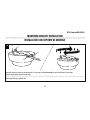
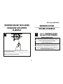
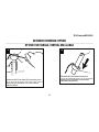
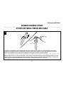
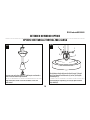
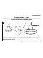
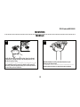
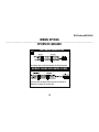
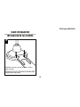
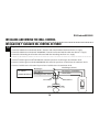
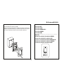
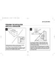
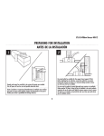
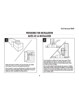
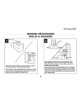
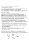
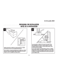
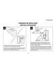
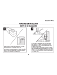
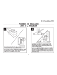
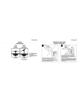
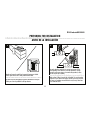
ETL-ES-IndustrialWC-WH14
PREPARING FOR INSTALLATION
ANTES DE LA INSTALACIÓN
2
1
Use metal outlet box suitable for fan support (must support 35 lbs).
Before attaching fan to outlet box, ensure the outlet box is securely
fastened by at least two points to a structural ceiling member (a loose
box will cause the fan to wobble).
Use una caja de embutir de metal adecuada para soportar un ventilador
(debe soportar 35 libras). Antes de fijar el ventilador a la caja de embutir
asegúrese de que la misma esté fijada de manera segura en por lo menos
dos puntos a un miembro estructural del cielo raso (una caja suelta haría
que el ventilador oscile).
Unpack and inspect fan carefully to be certain all contents are included.
Turn off power at fuse box to avoid possible electrical shock.
Quite el envoltorio e inspeccione detenidamente el ventilador para verificar
que todas las piezas estén incluidas. Apague la alimentación en la caja de
fusibles para evitar la posibilidad de descarga eléctrica.
4
ETL-ES-IndustrialWC-WH14
MOUNTING BRACKET INSTALLATION
INSTALACIÓN CON SOPORTE DE MONTAJE
3
2
1
2
1
Remove the screws and star washers from the two mating holes (1) on the canopy. Loosen (do not remove) the screws in the mating slots (2) on the canopy.
Rotate the mounting bracket and remove from the canopy.
Quite los tornillos y las dos arandelas en estrella de los dos orificios coincidentes (1) del dosel. Afloje (no quite) los tornillos de las ranuras coincidentes (2) del dosel.
Gire el soporte de montaje y sepárelo del dosel.
5
ETL-ES-IndustrialWC-WH14
MOUNTING BRACKET INSTALLATION
INSTALACIÓN CON SOPORTE
DE MONTAJE
MOUNTING OPTIONS
OPCIONES DE MONTAJE
4
5
Choose a MOUNTING OPTION
Elija una OPCIÓN DE MONTAJE
NORMAL DOWNROD OPTION
If installing downrod supplied with fan, proceed to page 12, step 13.
OPCIÓN CON VARILLA VERTICAL PARA CIELORRASO NORMAL
Si instala la varilla vertical incluida con el ventilador,
proceda a la página 12, paso 13.
EXTENDED DOWNROD OPTION
If installing with longer downrod than supplied with fan, proceed to page 7, step 6.
OPCIÓN CON VARILLA VERTICAL MÁS LARGA
Si instala una varilla vertical más larga que la que se incluye con el
ventilador, proceda a la página 7, paso 6.
Install mounting bracket to outlet box in ceiling using the screws and washers provided with the outlet box.
Instale el soporte de montaje a la caja de embutir del cielorraso con la
tornillería suministrada con la caja de embutir.
6
ETL-ES-IndustrialWC-WH14
EXTENDED DOWNROD OPTION
OPCIÓN CON VARILLA VERTICAL MÁS LARGA
6
3
5
1
4
6
2
Loosen set screws on the lower canopy (1). Lift up the lower canopy, take out the cotter pin (5), unloosen and remove the lock washer (3) , the nut (4), the cross pin (6)
from the yoke (2), and keep all of them for future usage, take out the down rod from the yoke and canopy.
Loosen set screws on the lower canopy (1). Lift up the lower canopy, take out the cotter pin (5), unloosen the lock washer (3) and the nut (4), remove the cross pin (1)
from the oke (2), and all of them for future usage, take out the down rod from the yoke and canopy.
7
ETL-ES-IndustrialWC-WH14
EXTENDED DOWNROD OPTION
OPCIÓN CON VARILLA VERTICAL MÁS LARGA
7
8
3
2
1
2
1
Slide downrod ball (1) off of downrod and remove pin (2).
Deslice la esfera de la varilla vertical (1) hasta separarla de la
varilla vertical y quite el pasador (2).
Loosen downrod ball (1) from downrod (2) by removing set screw (3).
Afloje la esfera de la varilla vertical (1) de la varilla vertical (2)
quitando el tornillo (3).
8
ETL-ES-IndustrialWC-WH14
EXTENDED DOWNROD OPTION
OPCIÓN CON VARILLA VERTICAL MÁS LARGA
9
Re-install pin into extended downrod, and slide downrod ball up to the top of the downrod. Re-install set screw to secure ball to downrod. Note: Some extended
downrods have a pre-drilled set-screw hole. If a pre-drilled hole is present in the extended downrod, tighten the set screw into the pre-drilled hole in the extended
downrod. If no pre-drilled hole exists in the extended downrod, tighten the set screw against the downrod to secure the downrod ball.
Vuelva a instalar el pasador en la varilla vertical más larga y deslice la esfera de la varilla hasta el extremo superior de la misma. Vuelva a insertar el tornillo de
fijación para asegurar la esfera a la varilla vertical. Nota: Algunas varillas verticales más largas tienen un agujero previamente perforado para el tornillo. Si la varilla
vertical más larga tiene un agujero previamente perforado, ajuste el tornillo en el agujero previamente perforado de la varilla vertical más larga. Si la varilla vertical
más larga no tiene un agujero previamente perforado, ajuste el tornillo sobre la varilla vertical para asegurar la esfera de la misma.
9
ETL-ES-IndustrialWC-WH14
EXTENDED DOWNROD OPTION
OPCIÓN CON VARILLA VERTICAL MÁS LARGA
11
10
3
5
4
1
2
1
Loosen set screws on the lower canopy (1). Install canopies onto downrod as
shown. Thread lead wires through the downrod.
Thread leadwires through the downrod and install crosspin (1) through
yoke (2) and downrod. Install lockwasher (3) and nut (4) and tighten.
Install cotter pin (5).
Afloje los tornillos de fijación en el dosel inferior (1). Instale los doseles en la
varilla vertical como se indica. Pase los hilos conductores a través de la
varilla vertical.
Instale el pasador transversal (1) a través de la grapa (2) y el eje central.
Instale la arandela de seguridad (3) y la tuerca (4). Aprete e instale la
clavija hendida(5).
10
ETL-ES-IndustrialWC-WH14
EXTENDED DOWNROD OPTION
OPCIÓN CON VARILLA VERTICAL MÁS LARGA
12
Aim the reverse switch on the yoke to the reverse switch hole in the lower canopy. Side the lower canopy down, make sure there is at least 1/4” clearance maintained
between the motor and lower canopy bottom and position the reverse switch properly. Tighten set screw in the lower canopy.
Direccione el interruptor de marcha atrás de la horquilla al orificio para el interruptor de marcha atrás correspondiente ubicado en el dosel inferior. Deslice el dosel inferior hacia
abajo, asegúrese de mantener un espacio de 6,4 mm (1/4 pulg.) entre el motor y la parte inferior del dosel inferior y luego posicione el interruptor de marcha atrás de forma apropiada. Ajuste el(los) tornillo(s) de fijación en el dosel inferior.
11
ETL-ES-IndustrialWC-WH14
MOUNTING
MONTAJE
13
14
Carefully lift fan assembly onto mounting bracket. Rotate fan until notch
on downrod ball (1) engages the ridge on the mounting bracket (2). This
will allow for hands free wiring.
Levante con cuidado el conjunto del ventilador hasta el soporte de montaje.
Gire el ventilador hasta que la muesca de la bola de la varilla vertical (1)
calce sobre la saliente del soporte de montaje (2). De este modo, tendrá las
dos manos libres para hacer el cableado.
With bracket holding fan assembly, make electrical connections using the
following step for wiring instructions.
Con la pieza de montaje sujetando el conjunto del ventilador, haga las
conexiones eléctricas de acuerdo a las siguientes instrucciones de cableado.
12
ETL-ES-IndustrialWC-WH14
WIRING OPTIONS
OPCIÓN DE CABLEADO
15
WALL CONTROL WIRING OPTION
Follow diagram above to make wiring connections for wall control operation.
OPCIÓN DE CABLEADO PARA CONTROL DE PARED
Siga las instrucciones del diagrama anterior para hacer las conexiones de
cableado para el ventilador con control de pared.
13
ETL-ES-IndustrialWC-WH14
SECURE TO CEILING
ASEGURE EL VENTILADOR AL CIELORRASO
16
3
2
1
For downrod fans, slide the canopy up to the mounting bracket. The canopy has two mating slots (1) and two mating holes (2). Position both slots on canopy directly under
and in line with two screws in the mounting bracket (3). Lift the canopy, allowing the two screws and star wahers to slide into the mating slots. Rotate the canopy until both
screws from the mounting bracket drop into the slot recesses. Tighten screws securely. Install two screws and star washers into the mating holes of the canopy and tighten
to secure the canopy to the mounting bracket.
Para ventiladores con varilla vertical, deslice el dosel hacia arriba hasta el soporte de montaje. El dosel tiene dos ranuras coincidentes (1) y dos orificios coincidentes (2).
Coloque ambas ranuras del dosel directamente abajo y en línea con los dos tornillos del soporte de montaje (3). Eleve el dosel, permitiendo que los dos tornillos se deslicen
dentro de las ranuras. Gire el dosel hasta que ambos tornillos del soporte de montaje caigan dentro de las ranuras. Apriete los tornillos asegurándolos. Instale los dos tornillos y las arandelas en estrella en los orificios coincidentes del dosel y ajústelos para asegurar el dosel al soporte de montaje.
14
ETL-ES-IndustrialWC-WH14
BLADE INSTALLATION
INSTALACIÓN DE LAS PALETAS
17
3
Install blades to top of motor using screws and washers . See above
drawing for reference.
Instale las paletas en la parte superior del motor con la tornillería. Utilice
la ilustración anterior como referencia.
15
ETL-ES-IndustrialWC-WH14
INSTALLING AND WIRING THE WALL CONTROL
INSTALACIÓN Y CABLEADO DEL CONTROL DE PARED
18 Wiring the wall control.
1. Connect the Black wire marked with “AC IN L” from the wall control with the black wire from A. C. supply.
2. Connect the Black wire marked with “TO MOTOR L” from the wall control with the white wire from A. C. supply.
3. Connect the Grounding wire from the wall control with the Grounding wire from A. C. supply.
Instalación y cableado del control de pared.
1. Conecte el cable negro marcado “CA VIVO” del control de pared con el cable negro de suministro de CA.
2. Conecte el cable negro marcado “AL MOTOR VIVO” del control de pared con el cable blanco de suministro de CA.
3. Conecte el cable de tierra del control de pared con el cable de tierra de suministro de CA.
Black/Negro (AC IN L)
Black/Negro
AC SUPPLY/
ALIMEN TACIÓN CA
Black/Negro (To MOTOR L)
White/Blanco
Grounding/Conexión a tierra
Green/Verde
16
Green/Verde
White/Blanco
ETL-ES-IndustrialWC-WH14
Secure the face panel and wall-mounted control to the outlet box with two screws provided.
Operations:
0: Fan Speed OFF
4: Fan Speed HIGH
3: Fan Speed MEDIUM HIGH
2: Fan Speed MEDIUM
1: Fan Speed LOW
Asegure el panel delantero y el control montado en la pared
a la caja de embutir usando los dos tornillos provistos.
Operación:
0: Control de velocidad del ventilador APAGADO
4: Contr ol de velocidad del ventilador ALTA
3: Cont rol de velocidad del ventilador MEDIANA/ALTA
2: Control de velocidad del ventilad or MEDIANA
1: Control de velocidad del ventilad or BAJA
17