1
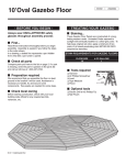
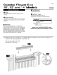
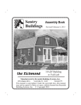
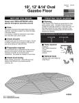
Revision:
Run:
10’, 12’ &14’ Round
Gazebo Floor
Instructions
- BEFORE YOU BEGIN Always wear OSHA-APPROVED safety
glasses throughout assembly process
■ First...
Read these instructions thoroughly before you begin
assembly. Assembly is easiest if you follow the steps
in the order shown.
In a drawing, a dotted line represents a part hidden
from view (like a part under a panel).
■ Check all parts
Compare parts you have to the list on page 2. If a part
is missing, circle the part in question in the parts list
and call us toll-free at 1-800-437-0784.
■ Preparation required
We recommend that you assemble this floor on level
ground in the location it will be used. Assistance is
necessary to handle, fit, and secure some
components. Two people are needed for some steps.
■ Check local zoning
Before starting construction, check with your local
building code official for any required permits,
variances, etc.
■ Check Floor Kit Size
10’ actual floor kit size is 9’-3” flat to flat or 10’ in
Diameter. 12’ actual floor kit size is 11’-8-3/4” flat to
flat or 12’-10” in Diameter. 14’ actual floor size has to
be a minimum of 14’-2” flat to flat or 15’ Diameter is
recommended.
#16693
10’- 8 sided Gazebo Floor
12’- 10 sided Gazebo Floor (not shown)
14’ - 12 sided Gazebo Floor (not shown)
9-08-03
Made in the U.S.A.
- TREATING YOUR GAZEBO ■ Staining...
This Gazebo Floor Panels are constructed of a longlasting western cedar. Untreated Cedar exposed to
sunlight will eventually weather to a silver-grey color. To
help keep original red color, applying of a minimum of
two coats of oil based penetrating stain WITHIN 30
DAYS (required by warranty).
STAIN REQUIREMENTS FOR GAZEBO FLOORS
FLOOR SIZE
10'
12'
14'
# OF GALLONS
1
1
1-1/2"
■ Tools required
❑ Hammer
❑ #2 Phillips Screwdriver
❑ Level
❑ Tape Measure
❑ Pencil
■ Optional tools
❑ Electric Drill w/ #2 Phillips Tip
❑ Nail Pouch
10’, 12’ & 14’ Gazebo Floor
8-Sided
10-Sided
12-Sided
■ Parts List 10’ Gazebo Floor Kit
❑ 8 pcs.
❑ 8 pcs.
❑ 1 pc.
❑ 1 pc.
❑ 2 pcs.
❑ 8 pcs.
❑
J1’s Treated
J2’s Treated
J3 Solid Center Block Treated
Base Plate Treated
J4 Center Deck Face Cedar
Pre-assembled Deck Panels Cedar
2-1/2” Screws, 3” Screws
J1 Treated
2 x 4 x 44-3/4”
2 x 4 x 54-3/4”
4 x 4 x 3-1/2”
2 x 8 x 7-1/2”
1” x 10-5/8” x 10-5/8”
Pre-drill on 10' Floor only
J2 Treated
■ Parts List 12’ Gazebo Floor Kit
❑ 10 pcs.
❑ 10 pcs.
❑ 1 pc.
❑ 1 pc.
❑ 2 pcs.
❑ 10 pcs.
❑
J4
J1’s Treated
2 x 6 x 44-3/4”
J2’s Treated
2 x 6 x 67-7/8”
J3 Hollow Center Block Cedar
6 x 6 x 5-1/2”
Base Plate Treated
2 x 8 x 7-1/2”
J4 Center Deck Face Cedar
1” x 7” x 7”
Pre-assembled Deck Panels Cedar
2-1/2” Screws, 3” Screws, 6” screw driver bit
J3
Center Deck Face
10' = 8 sided
10' = 8 sided
Solid Block
Center Deck Face
12' = 10 sided
■ Parts List 14’ Gazebo Floor Kit
❑ 12 pcs.
❑ 12 pcs.
❑ 1 pc.
❑ 2 pc.
❑ 2 pcs.
❑ 12 pcs.
❑
J3
J4
J1’s Treated
2 x 6 x 44-3/4”
J2’s Treated
2 x 6 x 81-1/16”
J3 Hollow Center Block Cedar
8 x 8 x 5-1/2”
Base Plate Treated
2 x 8 x 15”
J4 Center Deck Face Cedar
1” x 11” x 11”
Pre-assembled Deck Panels Cedar
2-1/2” Screws, 3” Screws, 6” screw driver bit
12' and 14'
Hollow Block
J4
Base Plate
Center Deck Face
14' = 12 sided
Note: Lumber is not marked with Part Letters Identification.
NATIONAL STANDARD LUMBER SIZES
Nominal size
Actual size
Pre-assembled Floor Panel
10' = 8 sided
12' = 10 sided
14' = 12 sided
2 x 4 = 1-1/2" x 3-1/2"
2 x 6 = 1-1/2" x 5-1/2"
2 x 8 = 1-1/2" x 7-1/2"
1
10’ and 12’ (1) Base Plate 2x8x7-1/2”
14’ (2) Base Plates 2x8x15”
FLOOR SYSTEM
ASSEMBLY
For Soft Surfaces Only. If building your Gazebo floor on the ground, use your baseplate.
10' Gazebo Center Block Pre-Drilled
Inside Holes Facing Up
12' Gazebo Center Block Pre-Drilled
Inside Holes Facing Up
Base Plate for Ground
Installation Only
(2) 3" Screws
14' Gazebo Center Block Pre-Drilled
Inside Holes Facing Up
Base Plate for Ground
Installation Only
(2) 3" Screws
2
(4) 3" Screws
Gazebo Floor
1
PARTS LIST 10’ FLOOR KIT
FLOOR SYSTEM
ASSEMBLY CONTINUED
❑ 8 pcs.
❑ 8 pcs.
❑ 1 pc.
PARTS LIST 12’ FLOOR KIT
NOTE: Assembly shown below is for 10’ Gazebo floor kit.
❑ 10 pcs.
❑ 10 pcs.
❑ 1 pc.
The 12’ and 14’ Gazebo floor kit assembles in the same
manner; however, there are two extra J1’s, J2’s and Deck
Panels for the 12’ and there are four extra J1’s, J2’s and
Deck Panels for the 14’. Follow Instructions below for
assembly of the 10’, 12’ and 14’ floor kit.
Fig.2
Note: Pre-drill Hole
in J2 at bottom
J1
J2
Step 1
Connects J1
to J1 with
3" screw.
PARTS
LIST J1’s
14’Treated
FLOOR KIT
❑ 12 pcs.
❑ 12 pcs.
❑ 1 pc.
10' Top View
2 x 6 x 44-3/4”
2 x 6 x 67-7/8”
6 x 6 x 5-1/2”
2 x 6 x 44-3/4”
2 x 6 x 81-1/16”
8 x 8 x 5-1/2”
Connect 12' & 14' Top View
with 3"
screws.
J3
Approx.
1/8"
J3
J2
Fig.5
Fig.1
J2
Connect with
Fig.4
(1) 3" screw down
inside with 6" Phillips Bit.
(Install after J1 and J2 are complete)
Fig.3
J1
Notch up and
to the inside
J2
J2’s Treated
J3 Hollow Center Block
2 x 4 x 44-3/4”
2 x 4 x 54-3/4”
4 x 4 x 3-1/2”
Top View
J2
1-A
J1’s Treated
J2’s Treated
J3 Hollow Center Block
Connects J2 10' Bottom View
to J3 with
3" screws.
J1
Step 2
Connects J1
to J2 with
3" screws.
J1’s Treated
J2’s Treated
J3 Solid Center Block
J2
J2
J2
J1
1-A: Step 3
1-A: Step 1
Locate the center of the area in which you will be
setting up your Gazebo floor kit. Start with the J3
Center Block with the pre-drilled holes on top. Lay out
eight J2’s around block with the pre-drilled holes
facing downward as in FIG. 1 for 10’ Gazebo, see
Fig. 4 for 12’ and 14’ Models. Attach with one 3”
screw in each hole into J2’s maintaining
approximately 1/8” spacing between the J2’s and J3
Center Block.
IMPORTANT: Two people required for this step.
With all J2 boards secured to Center Block, carefully turn
the assembly over - 10’ Gazebo only and install one 3”
screw through each predrilled hole in J2’s into Center Block
as shown in Fig.5. You may have to remove Base Plate to
install screws from the bottom on the 10’ Gazebo Floor and
reinstall. If Installing a 12’ or 14’ Gazebo floor, do not turn
floor over. Install remaining 3” screws into Center Block with
6” bit supplied in kit as shown in Fig. 4.
1-A: Step 2
Layout all J1 parts on edge with the notch facing upward
and inward at the end of the J2’s forming a circular type
pattern as shown in illustration above. Connect the J1’s to
J1’s as shown in Fig. 2 with one 3” screw. Be sure to keep
all joints even at top and outer edges at the angle joint.
Assemble remaining J1’s in this same manner except for
last pair of J1. Center the joint of the J1’s in the center of
the J2’s as shown in Fig. 2 and attach the J1 to the J2 with
two 3” screws as shown. Repeat this process to attach
remaining parts. You should then be able to carefully close
the final gap in the J1’s. You may need to adjust the gap
between J2 and J3 at this time.
Gazebo Floor
3
1
FLOOR SYSTEM
CONTINUED
PARTS LIST 10’ GAZEBO
PARTS LIST 14’ GAZEBO
❑ 8 pcs.
❑ 1 pc.
❑ 12 pcs.
❑ 1 pc.
Deck Panels
J4 Center Deck Face
Deck Panels
J4 Center Deck Face
PARTS LIST 12’ GAZEBO
❑ 10 pcs.
Deck Panels
❑ 1 pc.
J4 Center Deck Face
1-B
Notch in J1
is Facing Up
Fig.5
J2
J1
Turn Floor Over Again so
Notch in J1 is Facing Up
For 10’ Gazebo Floor
carefully turn floor over
again so notch is facing
up.
Top View
10' Floor
14' Floor
(4) 2-1/2"
Screws
12' Floor
J4
1-B: Step 1
Starting in one section, CAREFULLY
set Floor Panel in place as shown in
illustration above Fig. 5. Align Floor
Panels so that they are equally
spaced. DO NOT attach to J2’s!
Seams should line up directly over
center of J2’s. HINT: If last Floor
panel does not fit as desired, slightly
back out screws attaching J2’s to J3
Center Block. Once in place, you may
snug screws needed to back out for
tight fit. With all edges and seams and
edges aligned as desired, attach Floor
Panels through the pre-drilled holes
using 2-1/2” screws. Locate Center
Deck Plates J4 and align in center
opening keeping spacing equal on all
sides and attach with 2-1/2” screws as
shown in Fig. 6.
(4) 2-1/2" Screws
for 12' Floor
(4) 2-1/2"
Screws
J4
J4
(8) 2-1/2"
Screws
J4
Fig.6
J1 Corners
4
Gazebo Floor