1
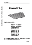
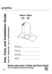
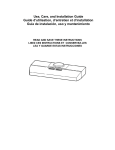
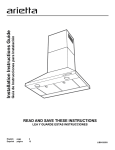
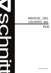
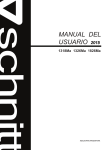
Recirculating KIT
PRO Hoods
Applicable models:
PRO001MX 30
PRO001MX 36
1
LI295A
WARNING:
•
Read and Save These Instructions.
•
Approved for Residential Appliances only.
•
PLEASE READ ENTIRE INSTRUCTIONS BEFORE PROCEEDING.
•
INSTALLER: Please leave these Instructions with this unit for the owner.
•
OWNER: Please retain these instructions for future reference.
•
Turn off power circuit at service panel and lock out panel before installing this kit to the appliance.
•
Installation must comply with all local codes.
PACKAGING CONTENTS
•
•
•
•
Air deflector
3 Charcoal Filters
12 springs
Mounting hardware
BEFORE INSTALLING THE RECIRCULATING KIT
The recirculation kit installation affects the hood installation, so take in consideration the following steps.
Cabinet or ceiling preparation when installing the recirculation kit
For cabinet or ceiling preparation take in consideration that there is no need to provide cutouts on walls for
vertical or rear air discharge, since there is no need to install any duct work. See the figure 1 for conduit
passage cut-out. See figure 2 for air passage cut-out on hood.
3-1/8” x 2-1/3”
Cut out for
conduit
passage
Cabinet
front
Bottom of
cabinet or
soffit
A
27/32”
Real
wall
12” min
Center
line
Hood width min.
Figure 1. Conduit Passage Cutout
Note:
The height of the hood with the recirculation kit installed, increases from 18" to 22“. Check that
there is enough clearance and that minimum height from the countertop to the bottom of the hood is
24” minimum for electric ranges to 30” minimum for gas ranges.
2
Figure 2. Air passage cut-out on hood
Hood Preparation
• The hood transition must not be installed, since no ductwork is necessary, if it is installed, remove
the transitions.
• Attach two pins B on top of the hood. See Figure 2. Make sure a Gap exists between the hood and
the hood surface.
Wall Mount Installation
First install the deflector on top of the hood, then install to the wall:
1) Attach four screws C on bottom of the deflector, do not tight completely, and leave approximately ¼”
from the bottom of the air deflector to the screw head. See Figure 2.
2) Install the deflector on top of the hood so that screws C and pins B go respectively into the existing side
slots at the top of the hood and the existing side slots at the bottom of the deflector (See Figure 2), slide
deflector frontward until it mechanically stops.
3) Tighten the four screws C from the inside of the hood.
4) Attach screws D from inside the hood through points E to attach the air deflector to the hood (see
Figure 2, number depends on hood size).
5) Proceed to install hood as described on the hood manual.
Installation under Cabinet
First install the deflector under the cabinet, and then install Hood to the air deflector:
1) Find the centerline at the bottom of the cabinet. Draw a line along this centerline from rear to the front of
the cabinet.
2) Draw two lines, one at a 1-1/2” of distance from the wall, then other at a 9-1/16“ distance from the
previous line. Identify and mark 4 points for the screw locations, divide by two the distance W, and
measure the obtained distance from the center line to the left and right sides, mark the points (see
Figure 3).
3) Attach 4 screws at the bottom of the cabinet (screws not supplied) do not tight completely; leave a
space of 1/2” from cabinet bottom surface and screw heads. Note: the screws must be able to support
the hood and deflector weight, and must be the right type according with the bottom cabinet surface.
4) Hang the deflector at the screws through the side slots present in the deflector top. Tight the four
screws through slots F. See Figure 2.
5) Attach four screws C at the bottom of the deflector, do not tight completely. See Figure 2.
6) Install the hood at the bottom of the air deflector so that screws C and pins B go respectively into the
existing side slots at the top of the hood and the existing side slots at the bottom of the air deflector
(See Figure 2), slide the hood rearward until it stops.
7) Remove 1 of 2 knockouts and install 1/2“conduit connector in j-box.
8) Attach screws, from inside of the hood through point E to final assembly Deflector to the hood (see
Figure 2, number depends on hood size).
3
Proceed to install hood as described in the Installation manual.
W
9-1/16”
1-1/2”
Center
Line
Screw for
cabinet bottom
installation
Figure 3. Marks in the cabinet
CHARCOAL FILTER INSTALLATION
•
•
Position the charcoal filter over the grease filter and insert the 4 springs (to prevent the movement).
Reinstall the grease filter onto the bottom of the hood.
Note: After 120 functional hours the charcoal filter must be replaced.
4
PRECAUCIÓN:
•
Lea y guarde estas instrucciones.
•
Aprobado para electrodoméstico residencial únicamente.
•
Por favor lea completamente estas instrucciones antes de proceder.
•
Instalador: Por favor deje estas instrucciones al propietario.
•
Propietario: Por favor mantenga estas instrucciones para futuras referencias.
•
Desconecte esta unidad del tablero de control eléctrico y asegure el panel de control antes de instalar
este accesorio a la campana.
•
La instalación debe cumplir con todos los estatutos locales.
CONTENIDO EN EMPAQUE
•
•
•
•
Deflector de aire
3 filtros de carbón
12 resortes
Materiales de montaje
ANTES DE INSTALAR EL ACCESORIO RECIRCULANTE
La instalación del accesorio afecta a la instalación de la campana. Tome en cuenta los siguientes pasos.
Preparación de gabinete o techo al momento de instalar el accesorio re circulante.
Para la preparación del gabinete o del techo, tome en consideración que no es necesario realizar cortes en
las paredes para la descarga de aire posterior o vertical, ya que no hay necesidad de instalar conductos.
Vea la figura 1 como referencia para los conductos de cableado. Vea la figura 2 como referencia para
aperturas en la campana.
3-1/8” x 2-1/3”
Corte para
conducto de
cableado
Parte
frontal del
gabinete
Parte
inferior del
gabinete
A
27/32”
Pared
posterior
12” min
Línea
central
Mínimo ancho de campana
Figura 1. Corte para pasar los conductos de cableado
Nota:
La altura de la campana junto con el accesorio re circulante aumenta de 18” a 22”. Verifique que
exista un espacio libre y que la distancia mínima desde el área de cocción a la campana sea de 24”
mínimo para estufas eléctricas y 30” mínimo para estufas de gas.
5
Figura 2. Apertura en la campana para el pasaje de aire.
Preparación de la campana
•
La transición metálica no debe ser instalada, ya que no habrá la necesidad de utilizar conductos, si
se encuentra instalada remuévala.
•
Asegure dos pivotes B en la parte superior de la campana. Como se muestra en la figura 2.
Asegúrese de que exista un espacio entre la campana y la superficie.
Montaje en pared
Primero instale el deflector de aire en la parte superior de la campana, después instálela a la pared:
1) Asegure cuatro tornillos C en la parte inferior del deflector, no los atornille completamente. Para
referencia vea la figura 2.
2) Instale el deflector en la parte superior de la campana para que los tornillos C y los pivotes B, vayan
respectivamente hacia el interior de los orificios laterales que se encuentran en la parte superior de la
campana, y los orificios laterales que se encuentran en la parte inferior del deflector se deslicen hacia
delante hasta que encuentren el tope. Observe la figura 2 como referencia.
3) Apriete los cuatro tornillos C desde la parte interna de la campana.
4) Asegure los tornillos D, desde la parte interna de la campana a través del punto E (Vea figura 2, el
número depende del tamaño de la campana).
5) Proceda a instalar la campana como esta descrito en el manual de instalación de la campana.
Instalación en gabinetes
Primero instale el deflector en la parte inferior del gabinete, después instale la campana al deflector
1) Encuentre la línea central en la parte inferior del gabinete. Dibuje una línea central desde la parte
posterior a la parte frontal del gabinete.
2) Dibuje dos líneas, una a 1-1/2” de distancia de la pared, la otra a 9 1/16” de distancia de la línea
previamente marcada. Marque 4 puntos para instalación de tornillos, divida la dimensión W, y marque
los puntos a la distancia obtenida, en la derecha e izquierda. Estos puntos deben ser marcados sobre
las líneas trazadas horizontalmente (vea la figura 3 como referencia).
3) Asegure 4 tornillos a la parte inferior del gabinete (tornillos no incluidos) no los apriete completamente
para dejar un espacio de 1/4” desde la parte inferior del gabinete a la cabeza del tornillo. Asegúrese de
que el tornillo sea capaz de sostener el peso de la campana y del deflector de aire, además, debe ser
del tipo correcto de acuerdo al material del gabinete.
4) Sostenga el deflector en los tornillos a través de los orificios laterales que se encuentran en la parte
superior del deflector. Asegure los cuatro tornillos a través de los orificios F (figura 2 como referencia).
5) Asegure 4 tornillos C en la parte inferior del deflector, no los apriete completamente. Vea figura 2.
6) Instale la campana en la parte inferior del deflector, de tal manera que los tornillos C y los pivotes B
pasen respectivamente al interior de los orificios laterales que se encuentran en la parte superior de la
campana y que los orificios que se encuentran en la parte inferior del deflector, se deslicen hacia atrás,
hasta que se encuentre el tope mecánico.Remueva una de las 2 tapas de la caja de conexión, e instale
el conducto de cableado de ½”, junto con la rosca para conductos eléctricos a la caja de conexión.
6
7) Remueva una de las 2 tapas de la caja de conexión, e instale el conducto de cableado de ½”, junto con
la rosca para conductos eléctricos a la caja de conexión.
8) Apriete los tornillos desde el interior de la campana a través del punto D (vea figura 2 como referencia,
el número depende del tamaño de la campana).
Siga con la instalación de acuerdo al manual de instalación de la campana.
W
9-1/16”
1-1/2”
Center
Line
Tornillo para
instalación en la
parte inferior del
gabinete
Figura 3. Marcas en el gabinete.
INSTALACION DEL FILTRO DE CARBON
•
•
Posicione el filtro de carbón sobre el filtro de grasa, e inserte las 4 abrazaderas (para sujetarlo).
Reinstale el filtro de grasa en la campana.
Nota: Después de 120 horas funcionales el filtro de carbón debe ser cambiado.
7