1
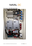
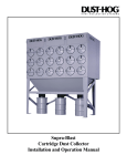
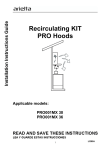
Guía de Instrucciones para Instalación
Installation Instructions Guide
READ AND SAVE THESE INSTRUCTIONS
LEA Y GUARDE ESTAS INSTRUCCIONES
English
Español
page página 2
12
LIB0102593
Table of Contents
APPROVED FOR RESIDENTIAL APPLIANCES
FOR RESIDENTIAL USE ONLY
Important Safety Notice ..........................................................2
Tools and parts ........................................................................3
Location Requirements ......................................................3
Product Dimensions ...........................................................3
Electrical Requirements .....................................................4
Venting Requirements ........................................................4
Venting Methods ................................................................4
Installation Instructions ..........................................................5
Electrical Connection...............................................................6
Hood Description......................................................................8
Controls...............................................................................8
Range Hood Care......................................................................9
Grease filter..........................................................................9
Replacing the light bulb........................................................10
Warranty.....................................................................................11
READ AND SAVE THESE INSTRUCTIONS
PLEASE READ ENTIRE INSTRUCTIONS BEFORE PROCEEDING.
INSTALLATION MUST COMPLY WITH ALL LOCAL CODES.
IMPORTANT: Save these Instructions for the Local Electrical
Inspector’s use.
INSTALLER: Please leave these Instructions with this unit for
the owner.
OWNER:Please retain these instructions for future
reference.
Safety Warning:Turn off power circuit at service panel and lock
out panel before wiring this appliance.
Requirement 120 VAC, 60 Hz. 15 or 20 A Branch Circuit
IMPORTANT SAFETY INSTRUCTIONS
WARNING: TO REDUCE THE RISK OF FIRE, ELECTRIC
SHOCK, OR INJURY TO PERSONS, OBSERVE THE
FOLLOWING:
WARNING: TO REDUCE THE RISK OF A RANGE TOP
GREASE FIRE:
■■ Never leave surface units unattended at high settings.
Boilovers cause smoking and greasy spillovers that may
ignite. Heat oils slowly on low or medium settings.
■■ Always turn hood ON when cooking at high heat or when
flambeing food (i.e. Crepes Suzette, Cherries Jubilee,
Peppercorn Beef Flambé).
■■ Clean ventilating fans frequently. Grease should not be
allowed to accumulate on fan or filter.
■■ Use proper pan size. Always use cookware appropriate for
the size of the surface element.
WARNING: TO REDUCE THE RISK OF INJURY TO
PERSONS IN THE EVENT OF A RANGE TOP GREASE FIRE,
OBSERVE THE FOLLOWING:a
■■ SMOTHER FLAMES with a close fitting lid, cookie sheet, or
metal tray, then turn off the burner. BE CAREFUL TO
PREVENT BURNS. If the flames do not go out
immediately, EVACUATE AND CALL THE FIRE
DEPARTMENT.
■■ NEVER PICK UP A FLAMING PAN - you may get burned.
■■ DO NOT USE WATER, including wet dishcloths or towels a violent steam explosion will result.
■■ Use an extinguisher ONLY if:
-You know you have a class ABC extinguisher, and you
already know how to operate it.
– The fire is small and contained in the area where it
started.
– The fire department is being called.
– You can fight the fire with your back to an exit.
■■ Use this unit only in the manner intended by the
manufacturer. If you have questions, contact the
manufacturer.
■■ Before servicing or cleaning the unit, switch power off at
service panel and lock the service disconnecting means to
prevent power from being switched on accidentally. When
the service disconnecting means cannot be locked, securely
fasten a prominent warning device, such as a tag to the
service panel.
■■ Installation work and electrical wiring must be done by
qualified person(s) in accordance with all applicable codes
and standards, including fire-rated construction.
■■ Sufficient air is needed for proper combustion and
exhausting of gases through the flue (chimney) of fuel
burning equipment to prevent backdrafting. Follow the
heating equipment manufacturer’s guideline and safety
standards such as those published by the National Fire
Protection Association (NFPA), the American Society for
Heating, Refrigeration and Air Conditioning Engineers
(ASHRAE), and the local code authorities.
■■ When cutting or drilling into wall or ceiling; do not damage
electrical wiring and other hidden utilities.
■■ Ducted fans must always be vented outdoors.
CAUTION: For general ventilating use only. Do not use to
exhaust hazardous or explosive materials and vapors.
CAUTION: To reduce risk of fire and to properly exhaust air,
be sure to duct air outside - do not vent exhaust air into
spaces within walls or ceilings, attics or into crawl spaces, or
garages.
Based on “Kitchen Fire Safety Tips” published by NFPA.
WARNING: To reduce the risk of fire or electrical shock,
do not use this fan with any solid-state speed control device.
a
WARNING: TO REDUCE THE RISK OF FIRE, USE ONLY METAL DUCTWORK
READ AND SAVE THESE INSTRUCTIONS
2
Tools and Parts
Gather the required tools and parts before starting installation.
Read and follow the instructions provided with any tools listed
here.
CAUTION:
Remove carton carefully, Wear gloves to protect against sharp
edges.
Location Requirements
IMPORTANT: Observe all governing codes and ordinances.
Have a qualified technician install the range hood. It is the
installer’s responsibility to comply with installation clearances
specified on the model/serial rating plate. The model/serial rating
plate is located behind the left filter on the rear wall of the vent
hood.
Canopy hood location should be away from strong draft areas,
such as windows, doors and strong heating vents.
Cabinet opening dimensions that are shown must be used. Given
dimensions provide minimum clearance.
Grounded electrical outlet is required. See “Electrical Requirements” section.
The canopy hood is factory set for venting through the roof or
wall. For non-vented (recirculating) installation, the KIT01937
must be purchased with your provider.
Tools needed (all models)
■■ Wire nuts
■■ Metal duct lenght to suit installation
■■
⁄2 ” Romex wire connector
1
■■ 6” rounded metal duct lenght to suit installation
■■ Measuring tape
■■ Pliers
■■ Gloves
■■ Knife
For Mobile Home Installations
The installation of this range hood must conform to the
Manufactured Home Construction Safety Standards, Title 24
CFR, Part 328 (formerly the Federal Standard for Mobile Home
Construction and Safety, Title 24, HUD, Part 280) or when such
standard is not applicable, the standard for Manufactured Home
Installation 1982 (Manufactured Home Sites, Communities and
Setups) ANSI A225.1/NFPA 501A, or latest edition, or with local
codes.
■■ Safety glasses
■■ Electric drill with 5⁄16” and 3⁄8” Bits
■■ Spirit level
■■ Duct tape
■■ Screwdrivers:
■■Philips (Posidrive #2)
■■Torx #2
■■ Wire cutter/ stripper
Product Dimensions
■■ Masking tape
103⁄4”
(27.3 cm)
■■ Hammer
6”
(15.24 cm)
■■ Saw, jigsaw or reciprocating saw
Parts Supplied
Remove parts from packages. Check that all parts are included.
■■ Hood canopy assembly with blower.
133⁄16”
(33.5 cm)
■■ Lamps already installed.
■■ Air transition
Ductless (recirculating)
version only
*Max 429⁄16” (108 cm)
*Min 284⁄16” (71.7 cm)
■■ Grease filter
■■ Duct covers
■■ Hardware package. Includes:
•
•
•
•
•
•
•
•
•
Ducted version only
*Max 3814⁄16” (98.76 cm)
*Min 249⁄16” (62.4 cm)
Template
Duct cover support bracket (1 piece)
Use, care and installation guide
Wood screws (6 pieces- 5 x 45 mm)
Concrete wall anchors (6 pieces- 8 x 40 mm)
Assembly screws (4 pieces - 4.2 x 8 mm)
Air transition screws (2 pieces - 3.5 x 9.5 mm)
TORX 10 adapter
TORX 20 adapter
5”
(12.6 cm)
30” (76.2 cm)
or
36” (91.4 cm)
Optional Accesories
■■ Recirculation KIT (KIT01937).
†®TORX is a registered trademark of Saturn Fasteners, Inc.
3
1911⁄16”
(50 cm)
Electrical Requirements
Makeup air
Local building codes may require the use of makeup air systems
when using ventilation systems with greater than specified CFM
of air movement. The specified CFM varies from locale to locale.
Consult your HVAC professional for specific requirements in your area.
IMPORTANT: The range hood must be electrically grounded in
accordance with local codes and ordinances, or in the absence
of local codes, with the National Electrical Code, ANSI/NFPA 70
(latest edition) or Canadian Electrical Code, CSA C22.1 No.
0-M91 (latest edition).
If codes permit and a separate ground wire is used, it is
recommended that a qualified electrical installer determine that
the ground path is adequate.
A copy of the above code standards can be obtained from:
National Fire Protection Association
1 Batterymarch Park
Quincy, MA 02169-7471
CSA International
8501 East Pleasant Valley Road
Cleveland, Ohio 44131-5575
■■ A 120 volt, 60 Hz, AC only, 15- or 20-amp, fused electrical
circuit is required. A time-delay fuse or circuit breaker is also
recommended. It is recommended that a separate circuit
serving only this range hood be provided.
■■
Venting Methods
This canopy range hood is factory set for venting through the
roof or through the wall.
A 6” (15.2 cm) round vent system is needed for installation (not
included). The hood exhaust opening is 6” (15.2 cm) round.
NOTE: Flexible vent is not recommended. Flexible vent creates
back pressure and air turbulence that greatly reduce performance.
Vent system can terminate either through the roof or wall. To vent
through the wall, a 90° elbow is needed.
Rear Discharge
A 90° elbow may be installed immediately above the hood.
For Non-Vented (Recirculating) Installations
If it is not possible to vent cooking fumes and vapors to the
outside, the hood can be used in the non-vented (recirculating)
version, using a Recirculation Kit (which includes charcoal filters
and a deflector). To order, see the “Optional Accesories” section.
To minimize possible shock hazard, the cord must be
plugged into a mating, 3 prong, grounding-type outlet,
grounded in accordance with local codes and ordinances. If a
mating outlet is not available, it is the personal responsibility
and obligation of the customer to have the properly grounded
outlet installed by a qualified electrician.
Exit through the roof
Exit through the wall
Recirculating
A
A
B
VENTING REQUIREMENTS
B
■■ Vent system must terminate to the outdoors.
C
C
B
A
C
■■ Do not terminate the vent system in an attic or other enclosed area.
■■ Do not use a 4” (10.2 cm) laundry-type wall caps.
■■ Use metal vent only. A rigid metal vent is recommended.
Plastic or metal foil vent is not recommended.
■■ The length of the vent system and number of elbows should
be kept to a minimum to provide efficient performance.
For the most efficient and quiet operation:
■■ Use no more than three 90° elbows.
A. Roof cap
B. Duct
C. Transition
■■ Make sure there is a minimum of 24” (61.0 cm) of straight
vent between the elbows if more than 1 elbow is used.
A. Wall cap
B. 90° Elbow
C. Transition
A. Air deflector
B. Duct
C. Transition
Preparation
Do not cut a joist or stud unless absolutely necessary. If a joist or
stud must be cut, then a supporting frame must be constructed.
Fittings material is provided to secure the hood to most types of
walls/ceilings.
However, a qualified technician must verify suitability of the materials in accordance with the type of wall/ceiling.
Before making cutouts, make sure there is proper clearance within
the ceiling or wall for exhaust vent.
Hood installation height above cooktop is the users preference.
The lower the hood is above the cooktop, the more efficient the
capturing of cooking odors, grease and smoke.
■■ Do not install 2 elbows together.
■■ Use clamps to seal all joints in the vent system and use
furnace duct tape to fully seal joint connection.
■■ Use caulking to seal exterior wall or roof opening around the cap.
■■ The size of the vent should be uniform.
Cold weather installations
An additional back draft damper should be installed to minimize
backward cold air flow and a thermal break should be installed to
minimize conduction of outside temperatures as part of the vent
system. The damper should be on the cold air side of the thermal break.
The break should be as close as possible to where the vent
system enters the heated portion of the house.
Set the hood’s mounting height based on the next recommendations:
■■ Minimum distance “X”: 24” (61.0 cm) from electric cooking
surface.
■■ Minimum distance “X”: 30” (76.2 cm) from gas cooking
surfaces.
■■ Suggested maximum distance “X”: 36” (91.4 cm).
4
Installation Instructions
Duckwork and wiring locations
Wall ducting
■■ Determine the exact location of the vent hood.
If ductwork will vent to rear:
■■ Locate the template packed with the literature.
■■ Use a level to draw a line straight up from the centerline on the
template.
■■ Installation height: 30” electric cooktop/range or 24” to 30”
electric cooktop/range.
■■
■■ Use a level to draw a horizontal straight pencil line on the wall,
wich is your desired installation height.
■■ Find the centerline of the cooktop. Use a level to draw a
vertical straight pencil line on the wall.
Measure at least 233⁄4”(The measure might vary depending on
the elbow used) above the pencil line that indicates the bottom
installation height, to the circle center of an 61⁄2” diameter duct
hole (Hole may be elongated for duct elbow).
House wiring location
■■ The junction box is located on the top left side of the hood.
■■ Wiring should enter the back wall at least 20” above the
bottom of the instalation height, and within 57⁄8” and 47⁄8” of the
left side of the centerline.
CHECK TO BE SURE THE LINE IS PERFECTLY
PERPENDICULAR.
Mounting the duct cover bracket
For ceiling vent ducting
43⁄4” circle
center to wall
The duct cover bracket should be installed against the back wall
and flush with the ceiling. This bracket will hold the duct cover in
place at the top.
Ceiling
61⁄2” dia.hole
Secure the bracket to the wall:
■■ Align the marked centerline on the bracket with the centerline
on the wall.
Circle center at
233⁄4” above the
marked bottom
pencil line
For wall
vent duct
■■ Mark 2 screws hole locations in the wall.
■■ Drill 5⁄16” pilot holes in the marked locations.
■■ Install wall fastener anchors.
■■ Drive wood screws, by hand, into the fastener to allow anchors
to expand. Remove the screws.
■■ Secure the bracked to the wall with wood screws and/or
fasteners.
Horizontal straight
pencil line
Install framing for hood support
■■ If drywall is present, mark the screw hole locations. Remove
the template.
■■ Cut away enough drywall to expose 2 vertical studs at the holes
location indicated by the template.
■■ Install two horizontal supports at least 1”x6” between two wall
studs at the bottom and top mounting holes installation location.
■■ The horizontal support must be flush with the room side of the
studs. Use cleats behind both sides of the support to secure to
wall studs.
■■ Reinstall drywall and refinish.
IMPORTANT: Framing must be capable of supporting 100 lbs.
61⁄2 minimum opening
for ductwork
Cleats view
from rear
Ceiling ducting
1˝ x 6˝ minimum
mounting support
If the duct will vent straight up to the ceiling:
■■ Use level to draw a line straight up, from the centerline on the template to the ceiling.
■■ Measure at least 43⁄4” from the back wall to the circle center of an 61⁄2” hole on the ceiling.
Centerline of
installation
space
5
Mounting the hood
1. Install transition on top of hood (if removed for shipping) with
■■ Mark “lower” wood screw holes locations in wall using a pencil.
2 - 3.5 x 9.5 mm sheet metal screws.
B
A
■■ Remove the hood.
■■ Drive the “lower” wood screws, by hand. Remove screws.
■■ Mount the hood onto the “upper” wood screws, by hand.
■■ Drive and tighten the “lower” wood screws, by hand.
A
A. Vent transition
B. 3.5 x 9.5 mm screw
B
WARNING
A
2 people are required to lift and position the hood
onto the mounting screws.
A. 5 x 45 mm screw
B. Mounting slots
Electrical Connection
■■ Place the template on the wall along the horizontal line, make sure
the template is leveled and centered with the centerline.
■■ Mark “upper” screw holes locations in the wall
IMPORTANT: Check to be sure that hole locations are leveled and
correctly centered bye the vertical centerline.
WARNING
■■ Drive “upper” wood screws by hand. Leave ¼” of distance between
the screw head and the wall.
¼˝
(6.4mm)
Electrical Shock Hazard
Warning: Turn off the power circuit at the service
panel before wiring this unit.
120 VAC, 15 or 20 Amp circuit required.
■■ Remove the grease filter and mount the hood onto the “upper screws”.
ELECTRICAL GROUNDING INSTRUCTIONS
THIS APPLIANCE IS FITTED WITH AN ELECTRICAL JUNCTION
BOX WITH 3 WIRES, ONE OF WHICH (GREEN/YELLOW) SERVES
TO GROUND THE APPLIANCE. TO PROTECT YOU AGAINST
ELECTRIC SHOCK, THE GREEN AND YELLOW WIRE MUST BE
CONNECTED TO THE GROUNDING WIRE IN YOUR HOME ELECTRICAL SYSTEM, AND IT MUST UNDER NO CIRCUMSTANCES BE
CUT OR REMOVED.
Failure to do so can result in death or electrical shock.
6
■■ Remove the knockout and the Junction box cover and install
the conduit connector (cULus listed) in junction box.
Mounting the duct cover
■■ Position the duct cover over the mounted hood.
■■ Slide the bottom of the duct into the glass area.
■■
Position the top of the duct over the duct mounting bracket. If a
telescopic duct cover is used, grab the upper part of the
telescopic duct cover, pull it and place it in the duct cover
mounting bracket.
■■ Secure the top of the duct with 2 assembly screws provided.
■■ If not already done, install 1⁄2” conduit connector in j-box.
NOTE: This connector is not included with vent hood.
■■ Run black (live), white (neutral), and green (earth) wires (#14 AWG)
according to the National Electrical Code or CSA Standards and local
codes and ordinances in 1⁄2” conduit from power supply to j-box.
■■ Secure the bottom of the duct with 2 assembly screws provided.
■■ Connect black, white, and green wires from power supply to black,
white, and green/yellow wires in j-box respectively.
■■ These connections should be done while always making reference to
the electrical diagram found inside the hood.
■■ Close j-box cover and reapply.
If range hood does not operate:
■■ Check that the circuit breaker is not tripped or the house fuse blown.
■■ Disconnect power supply.
■■ Check that wiring is correct.
■■ Install the grease filter and turn power on at service panel.
Keep your Installation Instructions and Use and Care Guide close to
range hood for easy reference.
■■ Check operation of the hood.
7
Description of the hood
1.
2.
3.
4.
5.
6.
7.
3. Display
■■ Shows the hood settings.
Blower and light controls
Lamp housings
Grease filter handle
Grease filter
Canopy
Duct covers
Recirculating grid
4. “-” Key. Speed Decrease / OFF
■■ This key is used to decrease the fan speed, or turn OFF the fan.
■■ The fan will turn OFF if the “-” key is pressed and the hood
was in the first speed.
■■ If the fan is at second speed and the “-” key is pressed, the fan
will be set to first speed.
■■ If the fan is at third speed and the “-” key is pressed, the fan
will be set to second speed.
■■ If the fan is OFF and the “-” key is pressed, the control
backlight will light up.
5. “+” Key. Speed Increase / ON
■■ This key is used to increase the fan speed, or turn ON the fan.
■■ The fan will turn ON if the “+” key is pressed and the hood was OFF.
■■ If the fan is at first speed and the “+” key is pressed, the fan
will be set to second speed.
■■ If the fan is at second speed and the “+” key is pressed, the
fan will be set to third speed.
■■ If the fan is at third speed and the “+” key is pressed, a beep
will sound.
Special functions
Clock programming
■■ The clock can be reprogrammed at any time except during an
active timed function.
Controls
■■ The clock can be displayed in a twelve hour format and valid
clock times are from 1:00 to 12:59.
This hood is equipped with an electronic motor and lamp control.
The control is able to set 3 different fan speeds, turn ON/OFF light
and has a timer function. In the following drawing are described
the main key functions.
■■ The clock can be reprogrammed pressing the “Timer” key for 5
seconds, and after, the clock can be adjusted with the “+” and
“-” keys. Colon “:” will flash indicating clock programming
mode.
12
■■
3
■■ The user can finish on reprogramming the clock pressing the
“timer” key.
1. Timer Key
■■ The default timer setting is 10 minutes, and it can be adjusted
between 20 minutes and 1 minute.
■■
The user can have minute increments / decrements of 1
minute, but if the user keep pressing the “+”/”-” keys for more
than 1 second, the increments / decrements will be of 5
minutes. During this option the control will round to the nearest
5 minutes.
■■ After 1 minute of no key pressed the control will accept the
programmed clock time and will add one minute to the set
clock.
After pressing the timer key, the control enters to a timer
setup mode, and user can adjust the timer countdown time
with the “-” and “+” keys within 5 seconds. The timer can be
initiated immediately pressing the timer key, after setting the
timer duration or pressing the timer key twice (default 10
minutes setting).
Grease filter saturation alarm
■■ After thirty fan functional hours, the display will show “Grease
Filter” if the fan is active. When this icon is shown in the
display, the grease filters installed are required to be washed.
■■ If not action occurs within 5 seconds the countdown will start.
■■ To reset the grease filter saturation alarm the user must press
the “+” key for 5 seconds, after this action the icon “grease
filter” is not display, and the hood has the normal display
operation.
■■ During the timer setup the “-” and “+” keys are dedicated to the
timer and no motor action will occur.
■■ Once initiated the timer, it can be cancelled by pressing the
timer key again.
2. Light Key
■■ Press lamp key to turn ON the light (Lamp state previously OFF).
■■ Press lamp key to turn OFF the light (Lamp state previously ON).
8
Charcoal filter saturation alarm (Recirculating accessories)
■■ After one hundred and twenty functional hours of the fan, the
display will show “Charcoal Filter” if the fan is active.
Range Hood Care
■■ When this icon flashes on display, the charcoal filters installed
are required to be replaced or reactivated.
The efficiency of the range hood system depends on the cleanliness of the
intake and filters.
■■
The frecuency of cleaning depends on the amount and type of cooking.
To reset the grease filter saturation indication the user must
press the “-” key for 5 seconds, after this time the icon
“charcoal filter” is not display and the hood has the normal
display operation.
■■ Do not use the ventilating system without the filters in place or with grease-laden filters or surfaces.
WARNING
Audible signal activation and deactivation
■■ The audible signals can be activated or deactivated pressing
the “Light” key for 5 seconds.
■■ If the audible signal is activated, a tone must sound and the
“Snd” symbol must appear on the display for 2 second.
■■ If the audible signal is deactivated, the “Snd” symbol must
appear on the display for 2 second and no sound must sound.
To avoid risk of fire and explotion do not use
flammable liquids or solvents.
Charcoal filter inclusion and exclusion (Recirculating
accessories)
■■ The charcoal filter inclusion or exclusion can be set by
pressing the “-” and “+” keys at the same time for 5 seconds.
Always unplug or disconnect the appliance from the power supply before
servicing.
WARNING
■■ The Inclusion or exclusion of charcoal filter must be selected
while the lamps and the motor are OFF.
■■ When the charcoal has been excluded, the charcoal filter
alarm is disabled.
Be sure the entire hood including the filters and
light bulbs has cooled and grease has solidified
before attempting to clean any part of the appliance.
Filters
The metal grease filters are made of stainless steel anodized aluminum
and are long lasting.
To Remove The Metal Grease Filters
■■ Turn the fan and lights off.
■■ Pull the spring release handle.
9
Hood Surface
Replacing the halogen lamp
CAUTION: Before replacing the lamps, disconnect power off
to prevent from being switched on accidentally.
Turn off the range hood and allow the halogen / incandescent
lamp to cool. To avoid damage or decreasing the life of the new
bulb, do not touch bulb with bare fingers. Replace bulb, using
tissue or wearing cotton gloves to handle bulb.
If new lamps do not operate, make sure the lamps are inserted
correctly before calling service.
Stainless Steel Surfaces: Wipe and dry stainless steel in the same
direction as the grain. Avoid using too much pressure, which may
mar the surface. To remove finger prints and give added shine,
use cleaners such as Stainless Steel Magic. Do not allow any
cleaning compounds to remain in contact with stainless steel for
extended periods.
Plastic Surfaces: Wipe with a moist soapy sponge. Rinse and dry.
■■ Disconnect power.
■■ Use a flat-blade screwdriver and gently pry the light cover
loose.
■■ Remove the lamp and replace with a 120-volt, 40-watt
maximum, halogen lamp made for a G-9 base.
Aluminum Mesh Filters: Clean filters in the dishwasher or by
agitating in sudsy water. Ensure that there is no soil trapped in the
fine mesh. Dry the filters before reinstalling them.
Optional Recirculating Kit
■■
■■
■■
■■
■■
■■ Replace the light cover.
■■ Reconnect power.
If the model is not vented to the outside, the air will be
recirculated through disposable charcoal filters that help
remove smoke and odors.
The charcoal filters cannot be cleaned.
They must be replaced.
The charcoal filters are clipped inside of each metal grease
filter (mounting instructions included with recirculating kit mod.
KIT01937).
The charcoal filters should be replaced every 4-6 months
(depending on hood usage).
NOTE: DO NOT rinse, or put charcoal filters in an automatic
dishwasher.
Cleaning
■■ Always use the mildest cleaner that will do the job. Use clean,
soft cloths, sponges or paper towels.
■■ Rub stainless steel finishes in the direction of the grain. Wipe
area dry to avoid water marks.
■■ After cleaning, place all parts in their proper positons before
using.
■■ The cleaners recommended below indicate a type and do not
constitute an endorsement. Use all products according to
package directions.
10
WARRANTY
TO OBTAIN SERVICE UNDER WARRANTY:
or any Service Related Questions, please call:
1-888-732-8018
Staple your receipt here.
Proof of the original purchase
date is needed to obtain service
under the warranty.
TO OBTAIN SERVICE UNDER WARRANTY: You must present proof of original purchase date.
Please keep a copy of your dated proof of purchase (sales slip) in order to obtain service under warranty.
Parts and Service Warranty:
For the period of one year from the date of the original purchase, we will provide free of charge, non consumable parts or components
that failed due to manufacturing defects. During this one year limited warranty, we will also provide, free of charge, all labor and in-home
service to replace the defective part.
What is Not Covered:
■■ Damage to the product caused by floods, act of God, fire and accidents.
■■ Damage caused after delivery.
■■ House fuses replacement or resetting of circuit breakers.
■■ Service trips to your home to teach you how to use or install the product.
■■ Light bulbs, metal, carbon filters and the other consumable parts.
■■ The natural wear of finish, and wear due to improper maintenance, use of corrosive and abrasive cleaning
products, pads, and oven cleaner products.
This warranty will be voided when:
■■ Product damaged due to improper installation and failure to follow installation instructions, delivery or maintenance.
■■ Incidental or consequential damage caused by possible defects with this appliance.
■■ Alteration or modification of the Product which may cause in damage to the Product, or failure to operate it
in accordance with specifications.
■■ Damage because of improper connection with equipment of other manufacturers.
■■ Failure of the product if it is negligence, abused, misused, or used for other than the intended purpose or used commercially.
■■ Improper repair, modification or servicing of the Product performed by third parties other than Authorized Agents.
Who is Covered:
This warranty is extended to the original purchaser for products purchased for ordinary home use in the 48 mainland states, Hawaii,
Washington D.C. Alaska, Guam, Puerto Rico and the Virgin Islands.
This warranty is non-transferable and applies only to the original purchaser and does not extend to subsequent
owners of this product. This warranty is made expressly in lieu of all other warranties, expressed or implied,
including, but not limited, any implied warranty of merchantability or fitness for a particular purpose, and all other
obligations on the part of Elicamex, provided, however, that if the disclaimer of implied warranties is ineffective under applicable law, the
duration of any implied warranties arising by operation of law shall be limited to 1 (one) year from the date of original purchase at retail
or such longer period as may be required by applicable law.
This warranty does not cover any special, incidental and/or consequential damages, nor loss of profits, suffered by
the original purchaser, its customers and/or the users of the Product.
Have your product proof of purchase with date ready for warranty issues.
Or write to:
Elicamex
Av. La Noria #102
Parque Industrial Querétaro KM 28.5
Carretera Querétaro- San Luis Potosí
C.P 76220
México
11
ÍNDICE
APROBADO PARA APARATOS
DE USO DOMÉSTICO
SÓLO PARA USO DOMÉSTICO
LEA Y GUARDE ESTAS INSTRUCCIONES
Instrucciones de Seguridad Importantes ..............................12
Lista de Materiales....................................................................13
Requisitos de ubicación.......................................................13
Dimensiones del producto...................................................13
Requisitos eléctricos............................................................14
Requisitos de ventilación.....................................................14
Métodos de ventilación........................................................14
Instrucciones de instalación....................................................15
Conexión eléctrica....................................................................16
Descripción de la campana......................................................18
Controles..............................................................................18
Limpieza y cuidado de la campana.........................................19
Filtro contra la grasa............................................................19
Reemplazar las luces..........................................................20
Garantía.....................................................................................21
ANTES DE CONTINUAR, LEA LAS INSTRUCCIONES POR COMPLETO.
LA INSTALACIÓN DEBE CUMPLIR TODA LA NORMATIVA LOCAL.
IMPORTANTE: Guarde estas instrucciones para su uso por parte del inspector de electricidad local.
INSTALADOR: Entregue al propietario estas instrucciones junto con la unidad.
PROPIETARIO: Conserve estas instrucciones para futuras consultas.
Advertencia de seguridad: Antes de realizar el cableado de este
aparato, desactive el circuito de energía eléctrica en el panel de
servicio y desbloquee el panel.
Requisito: Circuito auxiliar de CA de 120 V, 60 Hz, 15 ó 20 A
INSTRUCCIONES IMPORTANTES DE SEGURIDAD
■■ Use esta unidad sólo de la manera para la que fue diseñada por el fabricante. Si tiene preguntas, póngase en contacto con el fabricante.
■■ Antes de dar servicio o limpiar esta unidad, apague el
suministro de energía en el panel de servicio, y bloquee los
medios de desconexión del servicio para evitar que se
encienda accidentalmente el suministro de energía.
Cuando el medio de desconexión del servicio no se pueda
bloquear, sujete de manera segura un dispositivo de
advertencia prominente, como podría ser una etiqueta, al
panel de servicio.
■■ El trabajo de instalación y cableado se debe llevar a cabo por una persona(s) calificada(s), en conformidad con todos los códigos y estándares aplicables, incluyendo construcciones clasificadas como resistentes al fuego.
■■ No opere ningún ventilador que tenga un cable o enchufe
dañado. Deshágase del ventilador o devuélvalo a un lugar de
servicio autorizado para que sea examinado y/o reparado.
■■ Es necesario que haya suficiente aire para la adecuada
combustión y ventilación de gases a través del conducto (la
chimenea) del equipo que consume combustible, para evitar que ocurra contratiro. Siga la guía y los estándares de
seguridad del fabricante del equipo de calefacción, como serían aquéllos publicados por National Fire Protection
Association (NFPA) (Asociación nacional de protección contra incendios), American Society for Heating, Refrigeration and Air Conditioning Engineers (ASHRAE) (Sociedad estadounidense para ingenieros de calefacción, refrigeración y acondicionamiento
de aire) y las autoridades de códigos locales.
■■ Cuando corte o taladre en una pared o techo, no dañe el
cableado ni otros servicios públicos ocultos.
■■ Los ventiladores con conductos siempre deben dar salida al
aire hacia el exterior.
CUIDADO: Para usarse solamente en ventilación común. No lo
utilice para ventilar materiales y vapores peligrosos o explosivos.
CUIDADO: Para reducir el riesgo de incendio y para ventilar el
aire adecuadamente, asegúrese de dirigir el conducto de ventilación hacia el exterior - no ventile el aire de salida a espacios
dentro de paredes o techos, áticos, espacios angostos o garajes.
ADVERTENCIA: PARA REDUCIR EL RIESGO DE INCENDIO,
SÓLO USE CONDUCTOS METÁLICOS.
12
ADVERTENCIA: PARA REDUCIR EL RIESGO DE INCENDIO
PROVOCADO POR GRASA EN LA SUPERFICIE DE LA ESTUFA:
■■ Nunca deje las unidades de superficie sin vigilancia cuando
estén en ajustes altos. Los derrames por hervor causan
salpicaduras grasosas y humeantes, las cuales pueden
encenderse. Caliente los aceites lentamente y con ajustes
bajos o medios.
■■ Siempre ENCIENDA la campana cuando cocine con calor
alto o cuando flamee alimentos (por ejemplo, crepes Suzette,
cerezas Jubileo y flameado de carne de res con pimienta).
■■ Limpie los ventiladores con frecuencia. No permita que se
acumule la grasa en el ventilador o en el filtro.
■■ Use cacerolas del tamaño adecuado. Siempre use utensilios
de cocción que sean los adecuados para el tamaño del elemento de la superficie.
ADVERTENCIA: PARA REDUCIR EL RIESGO DE LESIONES
A PERSONAS SI SE PRENDE FUEGO EN LA SUPERFICIE
DE LA ESTUFA OCASIONADO POR GRASA, OBSERVE LO
SIGUIENTE:a
■■ EXTINGA LAS LLAMAS con una tapa que encaje muy bien, una bandeja para galletas o una bandeja metálica, y luego apague el quemador. TENGA CUIDADO PARA EVITAR QUEMADURAS. Si las llamas no se extinguen de inmediato, EVACUE Y LLAME AL DEPARTAMENTO DE BOMBEROS.
■■ NUNCA AGARRE UNA CACEROLA QUE ESTÉ ARDIENDO - podría quemarse.
■■ NO UTILICE AGUA ni artículos de limpieza con agua,
incluyendo paños para vajilla o toallas mojadas - podría
ocurrir una explosión de vapor violenta.
■■ SÓLO use un extinguidor si:
– Sabe a ciencia cierta que tiene un extinguidor de clase
ABC y ya sabe cómo utilizarlo.
– El incendio es pequeño y se encuentra contenido en el
lugar en donde se inició.
– Ha llamado al departamento de bomberos.
– Puede apagar el fuego con una salida a su espalda.
a
Basado en “Consejos de seguridad para fuegos de cocina”,
publicado por la NFPA (Asociación nacional de protección
contra incendios).
ADVERTENCIA: A fin de reducir el riesgo de incendio o de
choque eléctrico, no use este ventilador con ningún dispositivo
semiconductor para el control de la velocidad.
Lista de Materiales
¡PRECAUCIÓN!
Quite la caja cuidadosamente, use guantes para protegerse contra los bordes afilados.
Requisitos de ubicación
IMPORTANTE: Observe todos los códigos y ordenanzas
aplicables. Deje que un técnico calificado instale la campana. Es
responsabilidad del instalador cumplir con las especificaciones de
instalación que vienen en la etiqueta de modelo y número serial. La
etiqueta de modelo/número serial está localizada detrás del filtro
izquierdo en la pared posterior de la campana.
La campana debe estar ubicada lejos de áreas con fuertes corrientes
de aire como ventanas, puertas y ductos de ventilación.
Una toma de tierra eléctrica es requerida. Vea la sección “Requisitos
eléctricos”.
Todas las aberturas en el techo y pared donde se ponga en contacto la
campana deben de ser selladas.
Esta campana está configurada para expulsar el aire através de
la pared o el techo. Para convertir a su versión recirculante, considere la adquisición del KIT01937 con su proveedor.
Reúna las herramientas y piezas necesarias antes de comenzar
la instalación. Lea y siga las instrucciones provistas con
cualquiera de las herramientas detalladas aquí.
Herramientas requeridas
■■ Tapones de cable
■■ Ducto metálico de 6”
■■ Conector romex de 1⁄2”
■■ Cinta métrica
■■ Cutter
■■ Pinzas para cortar y pelar cable
■■ Nivel
Para la instalación en casas rodantes
La instalación de esta campana debe hacerse conforme a los Estándares de Seguridad de la Construcción del Hogar, Título 24
CFR, Parte 328 (antes el Standard Federal para la Construcción y
Seguridad de Casas Móviles) o cuando el standard no sea aplicable al
Standard para la Instalación de Casas Manufacturadas 1982 (Casas,
manufacturación de casas e Instalación) ANSI A225.1/NFPA 501A, o
última edición, o códigos locales.
■■ Alicates
■■ Cinta de aislar
■■ Lentes de seguridad
■■ Destornilladores:
■■Phillips (Posidrive) #2
■■Torx #2
■■ Taladro con brocas: 5⁄16” y 3⁄8”
Dimensiones del producto
■■ Guantes de protección
■■ Masking tape
103⁄4”
(27.3 cm)
■■ Martillo
6”
(15.24 cm)
■■ Caladora o Taladro
Partes suministradas
Retire todas las partes del empaque. Verifique que estén incluidas
todas las partes.
■■ Campana con ventilador
133⁄16”
(33.5 cm)
■■ Lámpara ya instalada
Versión recirculante
*Max 429⁄16” (108 cm)
*Min 284⁄16” (71.7 cm)
■■ Transición redonda
■■ Filtro anti-grasa
Versión aspirante
*Max 3814⁄16” (98.76 cm)
*Min 249⁄16” (62.4 cm)
■■ Cubreductos
■■ Bolsa plástica con el siguiente contenido:
•
•
•
•
•
•
•
•
•
Plantilla de instalación
Guía de Uso, Cuidado e Instalación
Soporte metálico de cubreductos
6 tornillos para madera de 5 x 45 mm
6 taquetes de 8 x 40 mm
4 tornillos de instalación 4.2 x 8 mm
2 Tornillos 3.5 x 9.5 mm (para montar la transición)
Adaptador T10 TORX®†
Adaptador T20 TORX®†
5”
(12.6 cm)
30” (76.2 cm)
ó
36” (91.4 cm)
Accesorios opcionales
■■ KIT recirculante (KIT01937).
†®TORX es una marca registrada de Saturn Fasteners, Inc.
13
1911⁄16”
(50 cm)
Requisitos eléctricos
IMPORTANTE: La campana para cocina deberá estar conectada
a tierra de acuerdo con los códigos y ordenanzas locales, o en la
ausencia de códigos locales, con el National Electrical Code
(Código nacional eléctrico), ANSI/NFPA 70 (última edición) o el
Canadian Electrical Code (Código canadiense de electricidad),
CSA C22.1 No. 0-M91 (última edición).
Si los códigos lo permiten y se emplea un alambre de conexión a
tierra separado, es recomendable que un instalador eléctrico
calificado determine si la trayectoria de conexión a tierra es
adecuada. Usted puede obtener una copia de las normas de los
códigos arriba indicadas en:
National Fire Protection Association
1 Batterymarch Park
Quincy, MA 02169-7471
CSA International
8501 East Pleasant Valley Road
Cleveland, Ohio 44131-5575
■■ Se necesita un circuito eléctrico de 120 voltios, 60 hertzios,
CA solamente, de 15 ó 20 amperios y protegido con fusibles.
También se recomienda usar un fusible retardador o un
cortacircuitos. Asimismo se recomienda el uso de un circuito
independiente que preste servicio únicamente a esta
campana para cocina.
■■
Reguladores de aire
Los códigos de construcción local sugieren el uso de sistemas
reguladores de aire cuando se usen sistemas de ventilación mayores
a la CFM especificada o al movimiento del aire. El CFM especificado
varía dependiendo del área. Consulte a su técnico en ventilación para
conocer los requerimientos de su área.
MÉTODOS DE VENTILACIÓN
Opciones de ventilación
Esta campana ha sido configurada de fábrica para descargar el
aire através del techo o la pared.
Para su instalación se necesita de un ducto de ventilación de 6”
de diámetro (15.2 cm) (no incluido).
NOTA: No se recomienda el uso de ducto flexible; este crea
presión y turbulencia de aire que disminuye el desempeño.
El sistema de ventilación puede tener salida por el techo o por la
pared. Para emplear la salida a la pared, se necesitará un codo
de 90°.
Para instalaciones recirculantes
Si no es posible ventilar el humo de la cocina al exterior, la campana puede ser utilizada en su versión recirculante, utilizando un
Kit de recirculación (incluye filtros de carbón y deflector de aire).
Para ordenarlo, vea la sección “Accesorios Opcionales”.
Para reducir al mínimo el peligro de posibles choques
eléctricos, el cable debe estar enchufado en un contacto
apropiado de pared de 3 terminales, conectado a tierra de
acuerdo con los códigos y ordenanzas locales. Si no hay
disponible un contacto equivalente, es responsabilidad y
obligación personal del cliente de tener un contacto apropiado
con conexión a tierra instalado por un electricista calificado.
Salida através del techo
Salida através de la pared
Recirculante
A
A
B
B
REQUISITOS DE VENTILACIÓN
C
C
B
A
C
■■ El sistema de ventilación debe terminar en el exterior.
■■ No dirija la salida del sistema de ventilación hacia el desván u
otra área cerrada.
■■ No utilice una cubierta de pared de tipo para lavandería de 4”
(10,2 cm).
■■ Utilice ducto de escape de metal únicamente. Se recomienda
un ducto de escape de metal rígido. No se recomienda ducto
de escape de plástico u hoja metálica.
A. Boquilla de techo
B. Ducto
C. Transición
■■ El largo del sistema de ventilación y el número de codos se
deben mantener al mínimo para proveer un funcionamiento
eficaz.
Para obtener el funcionamiento más eficaz y silencioso:
A. Boquilla de pared
B. Codo de 90°
C. Transición
A. Deflector de aire
B. Ducto
C. Transición
■■ El diámetro del tubo debe ser uniforme.
Preparación
No corte una vigueta o un perno a menos que sea absolutamente
necesario. Si fuera necesario efectuar el corte, deberá construirse un
marco de soporte.
Se suministra el material de ajuste necesario para fijar la campana a la
mayoría de tipos de muro o techo.
No obstante, un técnico calificado debe comprobar la idoneidad de los
materiales de acuerdo con el tipo de muro o techo.
Antes de efectuar ningún corte, asegúrese de existe espacio libre
adecuado en el techo o muro para la expulsión del aire.
La preferencia de la altura de instalación de la campana de los usuarios es por encima de la cocina. Cuanto más cerca esté la campana de
la cocina, mas eficaz resultará la captura de olores, grasa y humos.
Instalaciones en climas frios
Una válvula de no retorno adicional debe ser instalada para reducir el
flujo de aire frío como parte del sistema de ventilación.
Un break térmico debe ser instalado para reducir la conducción de la
temperaturas exteriores al interior del sistema de ventilación.
La válvula deberá estar en el lado del aire frío del break térmico.
Configure la altura de instalación de su campana, de acuerdo a las
siguientes recomendaciones:
■■ Distancia mínima (estufas eléctricas): 24” (61.0 cm)
■■ Distancia mínima (estufas de gas): 30” (76.2 cm)
■■ Distancia máxima sugerida: 36” (91.4 cm)
■■ No use más de 3 codos de 90°.
■■ Asegúrese de que haya un mínimo de 24” (61,0 cm) de ducto
de escape recto entre los codos, si se utiliza más de 1 codo.
■■ No instale 2 codos lado a lado.
■■ Use abrazaderas para sellar todas las juntas en el sistema de
ventilación.
■■ Utilice silicón para sellar la pared exterior o la abertura del
techo alrededor del casquete.
14
Instrucciones para la
instalación
■■
Ubicación del ducto de salida y cableado
■■ Determine la ubicación exacta de la campana.
Mida al menos 233⁄4” (60.3cm; La medida puede variar
dependiendo del tipo de codo que se utilizará) por encima de la marca de lápiz que indica la parte baja de la campana,
al centro de la apertura circular de 61⁄2” para la salida del aire en el muro.
Ubicación del cableado
■■ Ubique la plantilla sobre la pared
■■ La caja eléctrica está localizada en la parte superior de la
campana.
■■ Utilice un nivel para dibujar una línea recta horizontal en la
pared, en donde se encontrará su altura de instalación.
■■ El cableado debe ubicarse en la pared al menos 20" por
encima del borde inferior de la campana, y entre 57⁄8" y 47⁄8" del
lado izquierdo de la línea de centro de la campana.
■■ Ubique la línea de centro de su campana. Utilice una regla y
lápiz para trazar una línea recta en su pared.
ASEGÚRESE QUE LA LÍNEA SEA PERFECTAMENTE
PERPENDICULAR
Orificio de salida
al techo
43⁄4” del centro del
círculo al muro
Techo
Montaje del soporte de cubreductos
orificio de 61⁄2”
de diámetro
El soporte de cubreductos debe ser instalado contra la pared
y nivelado con el techo. Este soporte sostendrá en su lugar al
cubreducto superior.
233⁄4” del centro
del círculo a la
línea horizontal
trazada a lápiz
Orificio de salida
a la pared
Sujete el soporte a la pared:
■■ Alinee la línea de centro marcada en el soporte con la línea de
centro de la pared.
■■ Marque la ubicación de los 2 orificios para tornillos en la pared.
■■ Perfore los orificios de 5⁄16” en los lugares señalados.
Línea horizontal
trazada con lápiz
■■ Instale los taquetes.
Instalación de los marcos de soporte de la campana
■■ Introduzca los tornillos, a mano, para permitir que los taquetes se
expandan. Retire los tornillos.
■■ Si se instalará sobre tablaroca, marque la ubicación de los
orificios. Retire la plantilla.
■■ Asegure el soporte a la pared con los tornillos de instalación.
■■ Retire suficiente tablaroca para exponer los 2 soportes
verticales en la ubicación de los orificios indicados por la
plantilla.
■■ Instale dos tiras horizontales de al menos 1” x 6” entre los
soportes horizontales a la altura de los orificios superiores e
inferiores.
Tech
Línea Central Vertical
o
■■ Resane la superficie.
IMPORTANTE: El marco debe ser capaz de soportar 100 lbs.
Pared
Soporte visto
desde atrás
soporte de
montaje de 1˝x6˝
Salida de aire por el techo
Si el ducto ventilará directamente hacia el techo:
■■ Utilice el nivel para marcar una línea vertical, de la línea de
centro de la plantilla al techo.
Línea de
centro en el
espacio de
instalación
■■ Mida al menos 43⁄4”, de la pared a la apertura circular de 61⁄2”
en el techo.
Salida por la pared
Si la salida será por la parte trasera:
■■ Utilice un nivel para continuar la línea de centro de la plantilla.
15
Instalación de la campana
1. Instale la transición en la parte superior de la campana con 2
■■ Marque la ubicación de los tornillos inferiores sobre la pared
utilizando un lápiz.
tornillos metálicos de 3.5 x 9.5 mm.
B
A
■■ Retire la campana.
■■ Inserte los tornillos inferiores a mano. Retírelos.
■■ Monte la campana sobre los tornillos superiores.
■■ Instale los tornillos inferiores.
A. Transición
B. Tornillos de instalación de 3.5 x 9.5mm
A
B
ADVERTENCIA
A
Se requieren 2 personas para levantar y ubicar la
campana en los tornillos de montaje.
A. Tornillos de 5 x 45 mm
B. Orificios de montaje
■■ Coloque la plantilla en la pared, asegúrese de que esté alineado
al centro de la plantilla.
Conexión Eléctrica
■■ Marque la ubicación de los tornillos superiores en la pared.
IMPORTANTE: Asegúrese de que los orificios estén nivelados y
correctamente ubicados a la línea de centro.
ADVERTENCIA
■■ Inserte los tornillos superiores a mano. Deje ¼” de distancia entre
el tornillo y la pared.
¼˝
(6.4mm)
Riesgo de Choque Eléctrico
Advertencia: Desconecte la corriente antes de iniciar con el cableado de esta unidad.
Se requiere de un cicuito de 120 VAC, 15 ó 20 Amp.
■■ Retire los filtros de grasa y monte la campana sobre los tornillos
superiores.
INSTRUCCIONES DE TOMA ELÉCTRICA ESTE APARATO
DISPONE DE UNA CAJA DE CONEXIONES ELÉCTRICAS
CON 3 CABLES, UNO DE LOS CUALES (VERDE Y AMARILLO)
SIRVE COMO TOMA DE TIERRA PARA EL APARATO PARA
PROTEGERSE DE DESCARGAS ELÉCTRICAS, EL CABLE
VERDE Y AMARILLO DEBE ESTAR CONECTADO AL CABLE
DE TOMA A TIERRA DE SU SISTEMA DOMÉSTICO DE
ELECTRICIDAD Y BAJO NINGUNA CIRCUNSTANCIA DEBE
CORTARSE O ELIMINARSE.
De lo contrario, podría tener como resultado una descarga
eléctrica o la muerte.
16
Montaje del cubreducto
■■ Quite la cubierta de la caja de terminales. Retire el disco
removible que está en la cubierta de la caja de terminales.
■■ Coloque los cubreductos sobre la campana.
■■ Deslice el cubreducto inferior en la parte superior de la campana.
■■ Coloque la parte superior del cubreducto sobre el soporte.
■■ Asegure la parte superior del ducto con 2 tornillos de montaje.
■■ Instale un protector de cables de ½" que esté en la lista de UL
o esté aprobado por CSA.
NOTA: Este conector no se incluye en su campana.
■■ Asegure los ductos por la parte inferior con 2 tornillos de
ensamble.
■■ Pasar los cables negro (línea), blanco (neutro) y verde (tierra)
(#14 AWG) de acuerdo al código eléctrico nacional, la
normativa CSA o normas y disposiciones legales locales;
por el tubo de corriente eléctrica de ½” desde el suministro
de corriente eléctrica hasta la caja de conexiones en la
campana.
■■ Conectar los cables negros (línea), blanco (neutro) y verdes
(tierra) desde el suministro de poder hacia los cables negros,
blancos y verdes respectivamente en la caja de conexiones.
■■ Estas conexiones deben ser realizadas siempre haciendo
referencia al diagrama eléctrico que se encuentra dentro la
campana.
■■ Cierre la caja de conexión y vuelva a instalar los tornillos.
■■ Instale los filtros de grasa y revise que la campana funcione
correctamente.
Si la campana no funciona:
■■ Verifique que los circuitos no estén dañados o algún fusible de
casa fundido.
■■ Desconecte el suministro eléctrico.
■■ Compruebe si el cableado es correcto.
17
Descripción de
la campana
■■ Durante el ajuste del temporizador, las teclas “-” y “+” son
dedicadas al temporizador y no ocurrirá ninguna otra acción
del motor.
■■ Una vez que el temporizador ha sido activado, puede ser
cancelado pulsando de nuevo la tecla temporizador.
1. Controles de luz y motor
2. Lámparas
3. Manijas del filtro de grasa
4. Filtro de grasa
5. Ensamble de campana
6. Cubreductos
7. Orificios de recirculación
2. Tecla de Iluminación
■■ Presione la tecla de iluminación para encender (La lámpara
debe estar previamente apagada).
■■ Presione la tecla de iluminación para apagar (La lámpara
debe estar previamente encendida).
3. Pantalla - Muestra la programación de la campana.
4. “-” Tecla. Disminución Velocidad/ OFF
■■ Esta tecla se usa para disminuir la velocidad del ventilador, o
para apagar (OFF) el ventilador.
■■ El ventilador se apagará ( OFF ) si se pulsa el botón “-” y la
campana estaba en la primera velocidad.
■■ Si el ventilador está en la segunda velocidad, se pulsa el
botón “-”, el botón será ajustado en la primera velocidad.
■■ Si el ventilador está en la tercera velocidad”-”se pulsa el
botón, el botón será ajustado en la segunda velocidad.
■■ Si el ventilador está apagado ( OFF) y se pulsa el botón “-”, se
iluminará la luz de la pantalla.
5. “+” Tecla. Aumento Velocidad / ON
■■ Esta tecla se usa para aumentar la velocidad del ventilador, o
encender el ventilador.
■■ El ventilador se encenderá si se pulsa el botón “+” y la
campana estaba apagada.
■■ Si el ventilador está en la primera velocidad y se pulsa el
botón “+”, el ventilador será ajustado en la 2a velocidad.
■■ Si el ventilador está en la segunda velocidad y se pulsa el
botón “+”, el ventilador será ajustado en la 3a velocidad
Controles
■■ Si el ventilador está en la tercera velocidad y se pulsa el botón
“+”, emitirá un sonido.
Esta campana está equipada con un control electrónico para
motor y para lámpara. El control tiene 3 velocidades para el
ventilador, enciende/apaga (ON/OFF) la luz y tiene la función
de temporizador (Timer). En el siguiente dibujo, están descritas
las funciones principales.
Funciones especiales
Programación del reloj
■■ El reloj, puede ser reprogramado en cualquier momento,
excepto durante una acción activa de temporizador.
■■ El reloj está configurado con el formato de doce horas y
los horarios válidos van de 1:00 a 12:59.
1. Tecla Temporizador
■■ El tiempo por defecto es 10 minutos, y puede ser ajustado
entre 20 minutos y un 1 minuto.
■■ Después de pulsar la Tecla Temporizador, el control accede
a la modalidad setup temporizador y el usuario, puede ajustar
la cuenta atrás del temporizador con las teclas “-” y “+” en 5
segundos.
■■
El temporizador puede ser usado inmediatamente, pulsando
la tecla del temporizador, después de haber establecido la
duración o pulsando la tecla del temporizador dos veces (por
defecto 10 min.).
■■
El reloj puede ser reprogramado pulsando la tecla
“Temporizador” por 5 segundos, y después, el reloj puede ser
ajustado con las teclas “+” y “-”. Colon “:” destellará indicando
la modalidad programación del reloj.
■■
El usuario puede incrementar / disminuir los minutos de 1
minuto, pero si sigue pulsando las teclas “+”/”-” por más de 1
segundo, los incrementos / disminuciones serán de 5 minutos.
Durante esta opción el control redondeará a los 5 minutos
más cercanos.
■■ El usuario puede terminar la reprogramación del reloj pulsando la tecla “timer”.
■■ Después de 1 minuto, si no se pulsa ninguna tecla, el control
aceptará la hora del reloj programada y añadirá un minuto a la
hora ajustada.
■■ Si el usuario no presiona ninguna tecla dentro de 5 segundos,
empezará la cuenta atrás.
18
Limpieza y cuidado de
la campana
Alarma de saturación de filtros de grasa
■■ Después de treinta horas de funcionamiento, el display
mostrará “Filtro de Grasa” si el ventilador está activo.
■■ Cuando este icono se muestra en el display, es necesario
lavar los filtros de grasa instalados.
■■
Para desactivar la alarma de saturación de filtros de grasa, el
usuario debe pulsar la tecla “+” por 5 segundos, después de
esta acción, el icono “filtro de grasa” no aparecerá en el display,
y la campana vuelve al display de funcionamiento normal.
La eficiencia de la campana depende de la limpieza de los filtros .
La limpieza de su campana depende del tipo y frecuencia de cocinado que
se lleva a cabo.
■■ No utilice el sistema de ventilación sin filtros.
Alarma de saturación del filtro de carbón
(accesorio de recirculación)
■■ Después de ciento veinte horas de funcionamiento del
ventilador, el display mostrará “Filtro de Carbón” si el ventilador está activo. Cuando este ícono se muestra en
el display, es necesario lavar o sustituir los filtros de carbón
instalados.
■■
ADVERTENCIA
Para reajustar la indicación de saturación de los filtros de
carbón, el usuario debe pulsar la tecla “-” por 5 seg, después,
el icono “filtro de carbón” no aparecerá en el display, y la
campana vuelve al display de funcionamiento normal.
Para evitar el riesgo de incendio y explosión, no
utilice líquidos flamables ni solventes.
■■ Desconecte siempre la campana, antes de llevar a cabo su limpieza.
ADVERTENCIA
Señal auditiva de activación y desactivación
■■ Las señales auditivas, pueden ser activadas o desactivadas
pulsando la tecla “Luz” por 5 seg.
■■ Si la señal auditiva es activada, un tono debe sonar y el
símbolo “Snd” aparece en el display por 2 seg.
■■ Si la señal auditiva es desactivada, el símbolo “Snd” aparece
en el display por 2 seg y no habrá ningún sonido.
Asegúrese de que toda la campana, incluyendo filtros y lámparas, se hayan enfriado antes de realizar
su limpieza.
Inclusión y exclusión del filtro de carbón
(accesorio de recirculación)
■■ La inclusión o exclusión puede ser establecida pulsando
los botones “-” y “+” al mismo tiempo por 5 segundos.
Filtros
■■ La inclusión o exclusión del filtro de carbón debe ser escogida
mientras las lámparas y el motor están apagados (OFF).
Los filtros de grasa están hechos de aluminio anodizado, son lavables y
de larga duración.
■■ Cuando el filtro ha sido excluido, la alarma del filtro de carbón
está desactivada.
Para remover los filtros de grasa metálicos
■■ Apague el motor y las lámparas.
■■ Jale las manijas del filtro y retírelos.
19
Superficies de la campana
Reemplace las lámparas halógenas
Apague la campana y permita que las lámparas se enfrien. Para
impedir el daño o deterioro en la vida útil de la lámpara, evite
manejar la lámpara directamente con los dedos. Reemplace la
lámpara utilizando un pañuelo o usando guantes para manejar la
lámpara.
Si las lámparas nuevas no funcionan, asegúrese de que están
colocadas correctamente antes de llamar al servicio.
Superficies de acero inoxidable: Limpie y seque el acero
inoxidable en la misma dirección que el cepillado. Evite utilizar
demasiada presión, lo que puede dañar la superficie. Para
eliminar huellas dactilares y dar más brillo, utilice productos
de limpieza. No permita que los compuestos de limpieza que
permanezcan en contacto con el acero inoxidable durante largos
períodos.
1. Desconecte la corriente.
2. Utilice un destornillador de punta plana y suavemente
retire la cubierta de la lámpara.
Superficies Plásticas: Frote con una esponja jabonosa. Enjuague
y seque.
3. Retire la lámpara y reemplácela por una lámpara
halógena de 120-volts, 40-watt máximo, con base G-9.
Filtros de malla de aluminio: Limpie los filtros en el lavaplatos o
agitándolos en solución jabonosa. Asegúrese de que no exista
polvo atrapado en la malla de aluminio. Seque los filtros antes de
reinstalarlos.
Kit Recirculante Opcional
■■ Si no puede llevar a cabo la expulsión de aire al exterior,
debe adquirir el Kit recirculante, paa que el aire sea
recirculado através de filtros de carbón deshechables que
ayuden a remover el humo y los olores.
■■ Los filtros de carbón no son lavables.
■■ Los filtros de carbón deben ser fijados a cada filtro de grasa.
(las instrucciones de montaje son incluidas en el kit
recirculante modelo KIT01937).
■■ Los filtros de carbón deben ser reemplazados cada 4-6 meses
(dependiendo del uso de su campana).
NOTA: NO enjuague, ni coloque los filtros de carbón dentro del
lavaplatos.
4. Coloque nuevamente la cubierta de la lámpara.
5. Conecte nuevamente la corriente.
Limpieza
■■
■■
■■
Utilice siempre solución jabonosa para limpiar. Utilice paños
suaves, esponjas o toallas de papel.
Frote los acabados de acero inoxidable en la dirección del
cepillado. Seque completamente el área para evitar marcas
de agua.
Después de limpiar, coloque las partes retiradas en su lugar.
20
GARANTÍA
Engrape su recibo aquí.
Como demostración de la adquisición,es
necesaria la fecha, para cualquier servicio
bajo garantía.
OBTENER SERVICIOS BAJO GARANTÍA:
O cualquier Pregunta Relacionada con los
Servicios, por favor, llame: 1-888-732-8018
OBTENER SERVICIOS BAJO GARANTIA: Usted debe presentar una prueba de la fecha original de
adquisición. Conserve una copia de su nota de compras con fecha, para obtener servicios bajo garantía
Garantía de componentes y servicio:
Por un periodo de un año desde la fecha original de compra, ofreceremos sin costo alguno, el reemplazo de piezas no
consumibles o componentes que han fallado debido a defectos de fabricación.
Durante este año de garantía limitada, también ofreceremos sin costo alguno, la mano de obra y el servicio en su domicilio
para reemplazar la parte defectuosa.
Lo que no cubre:
■■ Daños a la campana ocasionados por inundaciones, actos de Dios, fuego y accidentes.
■■ Daños causados después de la entrega.
■■ Reemplazo de fusibles o el reajuste de la caja de contactos del circuito eléctrico.
■■ Viajes de servicio a su domicilio para enseñarle a usar o instalar el producto.
■■ Lámparas, filtros de grasa, filtros de carbón y otras partes consumibles.
■■ El desgaste natural del acabado, así como el desgaste ocasionado por el mantenimiento inadecuado, el uso
de productos para limpieza corrosivos y abrasivos, y otros limpiadores para hornos.
Esta Garantía será anulada cuando:
■■ El producto ha sido dañado debido a una instalación inadecuada y no haber seguido las instrucciones para su instalación,
traslado o mantenimiento.
■■ Daños Incidentales o de consecuencia causados por posibles defectos de este electrodoméstico.
■■ Daños por alteración o modificación, al producto que puedan causar fallas en la operación de acuerdo con las especificaciones
funcionales.
■■ Daños debidos a conexiones inapropiadas con equipos de otros fabricantes.
■■ Daños al producto por ser usado con negligencia, abuso, uso indebido o utilizado para otros propósitos al cual fué fabricado, o
bien uso comercial.
■■ Reparaciones, modificaciones o servicios inadecuados realizados al producto por agentes no autorizado
Quien está cubierto:
Esta garantía se extiende al comprador original para productos comprados para uso doméstico en los 48 estados principales
de los Estados Unidos de América, Hawaii, Washington D.C., Alaska, Guam, Puerto Rico y las Islas Vírgenes.
Esta garantía es intransferible y aplica solamente para el comprador original y no se extiende a los propietarios subsecuentes
de este producto. La presente garantía sustituye expresamente cualquier otra garantía, ya sea expresa o implícita, incluyendo,
sin limitar, todas las garantías implícitas de comerciabilidad o idoneidad para un fin concreto, así como todas las demás
obligaciones a cargo de Elicamex. Sin embargo, en caso de que la renuncia a las garantías implícitas resultara inaplicable
de acuerdo a la ley vigente, la vigencia de cualquier garantía implícita derivada de la aplicación de la ley será limitada a un
periodo de 1 (un) año, contado a partir de la fecha de compraventa originaria al menudeo, o por un periodo mas amplio en
caso de que éste último sea previsto por la ley aplicable.
Esta garantía no cubre ningun daño especial, fortuito y/o consecuente, ni la pérdida de beneficios, sufridos por el comprador
original, de sus clientes y/o de los usuarios del producto.
Tenga su comprobante de compra con la fecha, lista para cuestiones de garantía.
O bien escriba a:
Elicamex
Av. La Noria #102
Parque Industrial Querétaro KM 28.5
Carretera Querétaro- San Luis Potosí
C.P 76220
México
21
22
23
LIB0102542 Ed. 10 / 14
Printed in Mexico