1
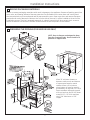
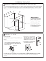
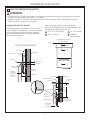
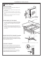
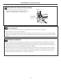
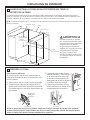
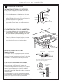
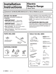
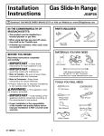
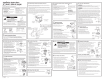
Installation Instructions 30” Electric Drop-In Ranges Questions?Call800.GE.CARES(800.432.2737)orVisitourWebsiteat:www.GEAppliances.com. InCanada,call1.800.561.3344orvisitwww.GEAppliances.ca. BEFORE YOU BEGIN •Note to Consumer –Keeptheseinstructionsfor futurereference. Read these instructions carefully and completely. •Skill level –Installationofthisappliancerequiresa qualifiedinstallerorelectrician. IMPORTANT — Savetheseinstructionsfor • localinspector’suse. •Properinstallationistheresponsibilityoftheinstaller. IMPORTANT — Observeallgoverning • codesandordinances. •Note to Installer –Besuretoleavethese instructionswiththeconsumer. •ProductfailureduetoimproperinstallationisNOT coveredunderthewarranty. ATTENTION INSTALLER: • Allelectricdrop-inrangesmustbehardwired(directwired)intoan approvedjunctionbox.AplugandreceptacleisNOTpermittedontheseproducts. FOR YOUR SAFETY WARNING Beforebeginningtheinstallation,switchpoweroffattheservicepanelandlockthe servicedisconnectingmeanstopreventpowerfrombeingswitchedonaccidentally.Whentheservice disconnectingmeanscannotbelocked,securelyfastenaprominentwarningdevice,suchasatag,totheservice panel. WARNING Theinformationinthismanualmustbefollowedtominimizetheriskoffire,electricshock, ortopreventpropertydamage,personalinjuryorlossoflife. WARNING Tip-Over Hazard A child or adult can tip the range and be killed. Verify the anti-tip bracket has been properly installed and engaged. Ensure the anti-tip bracket is re-engaged when the range is moved. Do not operate the range without the anti-tip bracket in place and engaged. Failure to follow these instructions can result in death or serious burns to children or adults. Countertop or Wood Block Anti-Tip Bracket MATERIALS YOU MAY NEED TOOLS YOU MAY NEED JunctionBox WireNuts StrainReliefClampfor1/2”Conduit 1/8”DrillBitandElectricDrill Level TapeMeasure StraightedgeorSquare HandorSaberSaw SafetyGlasses 31-10829GE10-11 1 Rear Wall Oven PhillipsScrewdriver FlatheadScrewdriver 1/4”NutDriver Hammer Pencil InstallationInstructions 1 REMOVE PACKAGING MATERIALS Failuretoremovepackagingmaterialscouldresultindamagetotheappliance.Removeallpackingpartsfrom oven,racks,andheatingelements.Removeprotectivefilmandlabelsontheouterdoorandcontrolpanel. Alsoremoveplasticontrimsandpanelandalltapearoundtheoven.Openovendoorandremoveliterature packandovenracks.Removethebottomtrimfromthesideoftheoven.Itwillbeinstalledattheendofthe installationprocess.Thetrimiswrappedseparatelyinaplasticbagwhichwillalsocontainthe4screwsto securethebottomtrimandthe2shoulderscrewsusedtosecuretheproducttothecabinet. 2 PREPARING THE OPENING (FOR INDOOR USE ONLY) NOTE: Drop-In Ranges are designed to hang from the countertop only. Do not install on a platform or support rails. Allow30”minimumclearance betweensurfaceunitsandbottom ofunprotectedwoodormetal cabinet.Allowa24”minimum whenbottomofwoodormetalis protectedbynolessthan1/4”thick flameretardantmillboardcovered withnotlessthanNo28MSGsheet metal(.015”),.015”thickstainless steel,.024”aluminumor.020” copper. 2 InstallationInstructions 2 PREPARING THE OPENING (Continued) Wall Flat area R 1/4”min.flat 23-3/16” 9/16”min. flat 25” typically 1/4” 9/16”min. flat 29-15/16”–30-1/16” smoothcut Rangesupport TheStandardInstallationofthisDrop-InRangeistohang bythecountertoponthesidemetalflangesunderglass cooktop.This Range must not be installed on a base or sub structure (2”x 4” support). Countertop Iftheconstructionofyourcabinetcannotprovidea 1/4”flatareaatthebackofthecountertopopening, considerchangingthecountertoptoaccommodatethis dimension.Iftheareaisnotflat,excesstensionmay beappliedtotheglasscooktop,causingbreakageand voidingthewarranty. •Countertopthickness1-1/4”min.isrequiredtosupporttheproduct.Bracesmustbeinstalledbetweenthe undersideofthecountertopandthecabinetifrequiredtoobtain1-1/4”minimumthickness(eachside). •Makesurethewallcoverings,countersandcabinetsaroundtheovencanwithstandtheheat(upto200°F (93.3°C)generatedbytheoven. •Thisappliancehasbeenapprovedfor0”spacingtoadjacentsurfacesabovethecooktop.However,a6” minimumspacingtosurfaceslessthan15”abovethecooktopandadjacentcabinetisrecommendedto reduceexposuretosteam,greasesplatterandheat. •Locatethewiringjunctionboxattherearofthecutout.Thedimensionfromthetopofthewiringjunction boxtothecountertopmustbeaminimumof28-1/2”.Theboxmustnotextendmorethan3”offtheplane ofthewall.Thejunctionboxmustbelocatedwhereitwillallowconsiderableslackintherangeconduit,so thattherangecanbepulledoutforserviceifnecessary. 3 InstallationInstructions 3 WHEN INSTALLING RANGE IN COUNTERTOP CUT OUT TO THE WALL Ifthecounteropeningextendstothewalls,itwillrequiremaintopfillerkit(JXS66XX)orback-guardkit(JXS36XX, JXS39SS,orJXS32XX)toclosethegap.Refertothefillerorbackguardkitinstructionsforinstallationdetails. NOTE:Ifthecountertopisgreaterthan25”itwillshowagapbetweentheback-guardandwallorbetween fillerkitandthewall. Must be Flat 25” 9/16” Wall Must be Flat 9/16” WARNING 10-3/8” from countertop to anti-tip support Anti-Tip Support Anadditionalanti-tipbracket supportmustbemountedto therearwallofthecutout. Theanti-tipbracketsupport istypicallya2x4pieceof lumberscreweddirectlyinto thewallstuds.Theanti-tip bracketsupportmustbeable towithstand200lbsofforce attheengagementpoint. 29-15/16” Min. 30-1/16” Max. 4 PREPARING THE RANGE Remove Oven Door Doorremovalisnotarequirementforinstallationof theproductbutisanaddedconvenience.Toremove thedoor: 1.Opentheovendoorasfarasitwillgo. 2.Pushbothhingelockstowardthedoorframe totheunlockedposition.Thismayrequireaflat bladescrewdriver. 3.Placehandsonbothsidesofthe door,andclosethedoortothe removalposition.Thisishalfway betweenthebroilstopandfully closed. 4.Liftthedoorupandoutuntilthe hingearmscleartheslots. Hinge Lock (Unlocked Position) Hinge Slot Hinge ClearsSlot Hinge Arm NOTE: The oven door is very heavy. Be sure you have a firm grip before lifting the oven off the hinges. Use caution once the door is removed. Do not lay door on its handle. This could cause dents or scratches. 4 InstallationInstructions 5A ELECTRICAL REQUIREMENTS WARNINGElectric Shock Hazard •Thisappliancemustbeproperlygrounded. •Donotuseanextensioncord. •Beforeinstallingrange,switchpoweroffattheservicepanelandlocktheservicedisconnectingmeans topreventpowerfrombeingswitchedonaccidentally.Whenthedisconnectionmeanscannotbelocked, securelyfastenaprominentwarningdevice,suchasatag,totheservicepanel. Failuretofollowtheseinstructionsmayresultinseriousinjuryordeath. WARNINGFire Hazard Improperconnectionofaluminumhousewiringtocopperleadscanresultinanelectricalorfirehazard.If residenceleadsarealuminum,useonlyconnectorsdesignedforjoiningcoppertoaluminumandfollowthe manufacturer’srecommendedprocedureclosely.Failuretodosomayresultinseriousinjuryordeath. Werecommendyouhavetheelectricalwiringandhookupoftheapplianceconnectedbyaqualified electrician.Afterinstallation,havetheelectricianshowyouhowtodisconnectpowerfromtheappliance. Youmustuseasingle-phase,120/208VACor120/240VAC,60Hertzelectricalsystem. EffectiveJanuary1,1996,theNationalElectricalCoderequiresthatnewconstruction(notexisting)utilizea four-conductorconnectiontoanelectricoven.Wheninstallinganelectricoveninnewconstruction,amobile home,recreationalvehicleorareawherelocalcodesprohibitgroundingthroughtheneutralconductor,refer tothesectiononfour-conductorbranchcircuitconnections. Checkwithyourlocalutilitiesforelectricalcodeswhichapplyinyourarea.Failuretowireyourovenaccording togoverningcodecouldresultinahazardouscondition.Iftherearenolocalcodes,yourovenmustbewired andfusedtomeettheNationalElectricalCode,NFPANo.70-latestedition,availablefromtheNationalFire ProtectionAssociation. Ratingplateislocatedonovenfrontframeandisvisiblewhenovendoorisopen. Thisappliancemustsuppliedbewiththepropervoltageandfrequency,andconnectedtoanindividual, properlygrounded,40amp(minimum)branchcircuitprotectedbyacircuitbreakerortime-delayfuse. DONOTshortentheflexibleconduit.Theconduitstrainreliefclampmustbesecurelyattachedtothejunction boxandtheflexibleconduitmustsecurelyattachedtotheclamp.Iftheflexibleconduitwillnotfitwithinthe clamp,donotinstalltheovenuntilaclampofthepropersizeisobtained. The3powerleadssuppliedwiththisappliancearesuitableforconnectiontoheaviergaugehousehold wiring.Theinsulationofthese3leadsisratedfortemperaturesmuchhigherthanthetemperatureratingof thehouseholdwiring.Thecurrent-carryingcapacityoftheconductorisgovernedbythewiregaugeandthe temperatureratingoftheinsulationaroundthewire. 5 InstallationInstructions 5B MAKE ELECTRICAL CONNECTIONS Placetheunitonaplatformortableevenwiththecutoutopening.Theplatformmustsupport200lbs.(91kg). Connecttheflexibleconduittotheelectricaljunctionboxasfollows: THREE-CONDUCTOR BRANCH CIRCUIT CONNECTION NOTE:Ifresidenceleadsorgroundarealuminumconductors,seeWARNINGinsection5A,Electrical Requirements. Whenconnectingtoathree-conductorbranchcircuit,iflocalcodespermit: 1.Connectthebareovengroundconductorwiththe crimpedneutral(white)leadtothebranchcircuit neutral(whiteorgrayincolor),usingwirenuts. Black Branch circuit Rangeconduit snapsintobox 2.Connecttheovenredleadtothebranchcircuitred lead,andtheovenblackleadtothebranchcircuit blackleadinaccordancewithlocalcodes,using wirenuts. 3.Installproperstrainreliefclamp. 4.Installjunctionboxcover. Red Alternate knockout Groundand neutralwires (white) Neutralbarewire connection FOUR-CONDUCTOR BRANCH CIRCUIT CONNECTION NOTE:Ifresidenceleadsorgroundarealuminumconductors,seeWARNINGinsection5A,Electrical Requirements. Whenconnectingtoafour-conductorbranchcircuit,iflocalcodespermit: 1.Cuttheneutral(white)leadfromtheclamp.Re-strip theneutral(white)leadtoexposetheproperlength ofconductor. Black 2.Attachtheappliancegroundinglead(greenorbare copper)inaccordancewithlocalcodes. Branch circuit Rangeconduit snapsintobox Ground wires 3.Connecttheovenneutral(white)leadtothebranch circuitneutral(whiteorgray)inaccordancewith localcodes,usingawirenut. 4.Connecttheovenredleadtothebranchcircuitred leadandtheovenblackleadtothebranchcircuit blackleadinaccordancewithlocalcodes,using wirenuts. Red Alternate knockout White 5.Installproperstrainreliefclamp. 6.Installjunctionboxcover. 6 InstallationInstructions 6 ANTI-TIP DEVICE INSTALLATION WARNING •Toreducetheriskoftippingtherange,therangemustbeproperlysecuredtothecountertoporrearwall usingtheanti-tipsuppport.(Seesection3fordetails.) •Weightonthedoorcouldpotentiallycausetherangetotipandresultininjury.Neverallowanyoneto climb,sit,stand,orhangontheovendoor. Installing the Anti-Tip Bracket Theanti-tipbracketisattachedtothebackofthe Drop-InRange.Itisdesignedtofitunderthebottom ofthecountertopopeningattherear.Measure counterthicknessatbackofcutouttodetermine correctbracketlocation. Selecttheproperpositionforthecountertop thicknessandmovebrackettoproperposition.(Unit issuppliedwithbracketinposition1.) 1For1.18”(3cm)Counter 3For3.5”Counter 2For1.5”Counter 4Alternate (shownbelow) Cooktop Anti-tipbracketlocation (rearofrange) ANTI-TIP INSTALLATION Interiorwall 1/4”min.flatarea Wallstud Maintop Countertop thickness Anti-tip bracket Bottomof countertop toengage bracketby 1/2”min. Bottomof countertop Wirecover Interiorwall Wallstud Non-kitapplication Maintop Attachment Countertop surface 10-3/8” Wire cover 1-1/2” Position #5non-kit application Anti-tipbracket *Attachment toengage bracketby1/2”min. 7 Attachment anchoredtowall studisrequired InstallationInstructions 7 INSTALL THE RANGE INSTALL STOP SCREW Thesescrewspreventtherangefromslidingoutof positionduringoperation. 1.Carefullymarkthecabinetforthelocationofthe stopscrews. 2.Drill1/8”pilotholesintocabinet,oneachsideof therange.(Donotdrillentirelythroughthecabinet wall.) 3.Carefullyturntheshoulderscrewsintothepilot holesuntiltheyaretight. Countertop PLACING RANGE INTO THE OPENING 1.Itisrecommendedthattwopeoplelifttherange intoplace,carefullysettingthesidemetalflanges undertheglassontheedgesofthecountertop opening. GapApprox.4” 2.Carefullyslidetherangetowardthebackofthe opening.Stoppushingtherangewhenthereistill a4”gapatthefrontbeforeflushingtherangewith thecounter. GapApprox.4” REMOVE THE PROTECTIVE CHANNELS (if provided) GlassCooktop Carefullyremovetheprotectivechannelsfromthe sidesoftheglasscooktop.Thismayrequireaslight liftingoftherangetoremovetheweightoftherange fromtheprotectivechannels. ProtectiveCover Remove Protective Cover from Both Sides after Range is in Cabinet CHECK ANTI-TIP BRACKET Withtherangestillsittingoutfromthecounter-top, confirmtheanti-tipbracketissecurelyattachedto therearoftherange,andslidetherangebacksothat theanti-tipbracketslidesjustunderthecountertopor woodblockattachedtotherearwall. Countertop or Wood Block Anti-Tip Bracket Iftherangeispulledfromthewallforanyreason, alwaysrepeatthisproceduretoverifytherangeis properlysecuredbytheanti-tipbracket. Oven 8 InstallationInstructions 7 INSTALL THE RANGE (Continued) ATTACH THE LOWER TRIM Attachthelowertrim(suppliedseparatelywiththe range)tothebottomoftheverticalsidetrimwiththe 4screwssupplied. Side trim Lower Trim Lower right endof front frame Attach2 screws each side LOCATING THE STOP SCREW Carefullyslidetherangetowardsthebackofthe opening.Whentherangeisapproximately1”from thebackoftheopening,liftthefrontoftherange approximately½”toclearthestopscrewlocated inthesidesofthecabinet.Slidetherangeuntilitis seatedintotheopening. Lowerthefrontoftherangeontothecounter-top. CHECK FOR PROPER INSTALLATION OF THE STOP SCREW Lookatbothsidesoftherangeunderthedoor.The stopscrewsmustbelocatedinthenotchonthe sidesoftherange,andnottouchthetopofthenotch whentherangeisfullyseatedonthecountertop.If thescrewsdonotmeettherequirements,movethe screwstoapositionthatmeetstheserequirements. (Seeillustration.) Lower Trim Clear Shoulder Screw NotchinBottom ofSideTrim 8 REPLACING THE OVEN DOOR Remove Oven Door 1.Lifttheovendoorbyplacingone handoneachside.thedooris heavy,soyoumayneedhelp.Do notliftthedoorbythehandle. 2.Withthedooratthesame Bottom angleastheremoval position(halfwaybetween Edgeof Slot theclosedandbroilstop position)seatthenotch ofthehingearmintothe bottomedgeofthehinge slot.Thenotchofthehinge armmustbefullyseated intothebottomoftheseat. 9 Hinge Arm HingeNotch InstallationInstructions 8 REPLACING THE OVEN DOOR (Continued) HingeinLocked Position 3.Openthedoorasfarasitwillopen.Pushthe hingelockupagainstthefrontframeoftheoven cavity,tothelockedposition.Closethedoor. NotchofHinge SecurelyFitted intoBottomof HingeSlot 9 FINAL CHECKLIST •Checktomakesurethecircuitbreakerisclosed(Reset)orthecircuitfusesarereplaced. •Besurepowerisinservicetothebuilding. •Checktobesurethatallpackingmaterialsandtapehavebeenremoved.Failuretoremovethesematerials couldresultindamagetotheapplianceoncetheappliancehasbeenturnedonandsurfaceelementshave heated 10 OPERATION CHECKLIST •ChecktomakesuretheClockdisplayisenergized.Ifaseriesofhorizontalredlinesappearinthedisplay, disconnectpowerimmediately.Rechecktherangewiringconnections.Ifchangeismadetoconnections, retestagain.Ifnochangeisrequired,havebuildingwiringcheckedforproperconnectionsandvoltage.Itis recommendedthattheclockbechangediftheredlinesappear. •Pushdownandturnanyoneofthefoursurfaceknobsto“MED”settingtoobservethattheelementglows within15seconds.Turntheknoboffwhenglowisdetected.Iftheglowisnotdetectedwithinthetimelimit, rechecktherangewiringconnections.Ifchangeisrequired,retestagain.Ifnochangeisrequired,have buildingwiringcheckedforproperconnectionsandvoltage. 10 Notes 11 12 PrintedintheUnitedStates Instrucciones de instalación Cocinas encastrables de 30” ¿Preguntas?Llameal1.800.GE.CARES(1.800.432.2737)ovisitewww.GEAppliances.com EnCanadá,llameal1.800.561.3344ovisitewww.GEAppliances.ca. ANTES DE COMENZAR • Nota al consumidor –estasinstruccionespara referenciafutura. • Nivel de destreza –Lainstalacióndeesteaparato requiereeltrabajodeuninstaladoroelectricista calificados. • Elinstaladortienelaresponsabilidaddeefectuar unainstalaciónadecuada. • L agarantíanocubrelasfallasdelproducto provocadasporunainstalaciónincorrecta. Lea estas instrucciones por completo y con detenimiento. IMPORTANTE • — Guardeestas instruccionesparaelusodeinspectoreslocales. IMPORTANTE — Cumplacontodoslos • códigosyordenanzasvigentes. •Nota al instalador –Asegúresededejarestas instruccionesconelconsumidor. • ATENCIÓN INSTALADOR: Todaslascocinasencastrableseléctricasdebencontarcon cableadodeconexiónpermanente(cableadodirecto)dentrodeunacajadeconexionesaprobada.Enestos productosNOsepermitelaconexióndeltipo“enchufeyreceptáculo”. PARA SU SEGURIDAD ADVERTENCIA Antesdecomenzarlainstalación,desconectelaenergíadelpaneldeservicioy bloqueelosmediosdedesconexiónparaevitarelaccionamientodelaenergíademaneraaccidental.Cuandolos mediosdedesconexióndeservicionopuedenbloquearse,coloquesobreelpaneldeservicioundispositivode advertenciabienvisible,comounaetiqueta. ADVERTENCIA Lainformacióndeestemanualdebeseguirsealpiedelaletraafindeminimizarel riesgodeincendios,descargaseléctricas,oparaprevenirdañosalapropiedad,lesionespersonalesolamuerte. ADVERTENCIA Riesgo de Volcaduras Un niño o adulto pueden volcar la cocina y morir. Instale el dispositivo anti-volcaduras (tornillos o soporte) de acuerdo con las siguientes instrucciones. Vuelva a colocar el soporte anti-volcaduras si la estufa se mueve de lugar. Si estas instrucciones no se siguen, como resultado se podrá producir la muerte o quemaduras graves de niños y adultos. Base o Bloque de Madera Soporte Anti-Volcaduras Hornov Pared Trasera MATERIALES QUE PUEDE NECESITAR HERRAMIENTAS NECESARIAS Cajadeconexiones Taponesdealambre Abrazaderadealiviodetensiónparaconductode1/2” Brocadeperforadorade1/8”yperforadoraeléctrical Destornilladordeestrella Nivel Destornilladorconpuntaplana Cintamétrica Llavedetuercasde1/4” Martillo Puntaderechaocuadrada Lápiz Sierrademanoosierrasable GafasdeSeguridad 31-10829GE10-11 1 Instruccionesdeinstalación 1 QUITE LOS MATERIALES DE EMPAQUE empaquedelhorno,bandejasyelementosdecalentamiento.Quitelapelículaprotectoraylasetiquetasdela puertaexteriorypaneldecontrol.Además,quiteelplásticodelosrebordesypanelytodalacintacolocada alrededordelhorno.Abralapuertadelhornoyquiteelmaterialinformativoylasbandejasdelhorno.Quite elrebordeinferiordelapartelateraldelhorno.Secolocaráalfinaldelprocesodeinstalación.Elbordeestá envueltodeformaaparteenunabolsaplásticaquetambiéncontendrá4tornillosparaasegurarelborde inferiorylostornillosdetopeusadosparaasegurarelproductoalgabinete. 2 PREPARE LA ABERTURA (SÓLO PARA USO EN EL INTERIOR) Profundidad total de 26-1/2” NOTA: Las cocinas empotrables son diseñadas para colgar de la base únicamente. No instale sobre una plataforma de rieles con soportes. 5-5/8” Bobina 2-7/8” Radiante hasta la superficie frontal de la base Franjas de protección (si se suministran) 20-5/8” Espacio hasta la puerta desde la superficie de la base Mín. de 27-1/2” Siga las instrucciones embaladas con los electrodomésticos alternativos. (Se deberá mantener una dim. mín. de 24" entre la superficie de la cocina y el lado inferior del electrodoméstico) Soportes del relleno de la parte frontal Mín. de 30” Se recomienda un mín. De 6” desde las paredes Para una instalación óptima, estas superficies deberá ser planas y estar a nivel 35 ½” a 36 ½” desde la puerta hasta la base 23-3/16” Área del tomacorrientes eléctrico aceptable. También en el gabinete adyacente o debajo del piso Profundidad máx. de 13” Mín. de 30” desde la superficie de cocina hasta la parte inferior de los gabinetes elevados 1/4” plano Muestra del Tablero Posterior Preformado Relleno del gabinete frontal (si se requiere) Distancia vertical mín. 15” desde la parte inferior de los gabinetes adyacentes elevados Profundidad de la base de 25” Mín. de 1-1/4” desde la base a la parte superior del cajón 7-1/2” 9/16” Mín. de 29 15/16” Máx. de 30 1/16” Afeitar borde levantado para eliminar 31-1/8 " de ancho del panel 2 30” Dejeunespaciomínimode30” entrelasunidadesdelasuperficie ylaparteinferiordelgabinetede maderaometalsinprotección.Deje unespaciomínimode24”cuando laparteinferiordelamaderao metalesténprotegidasporcartón deretardodeincendiosde1/4”de grosor,cubiertoconnomenosque unahojadeaceroinoxidableNº28 MGSde0.15”,dealuminiode0.24”o decobrede.020”degrosor. Instruccionesdeinstalación 2 PREPARE LA ABERTURA (Continuación) Pared Área plana R Mín.de¼” plano 23-3/16” Mín.de9/16” plano Típicamente de25” 1/4” Min.de9/16” plano Corteparejode 29-15/16”-30-1/16” Soportedelaestufa LaInstalaciónEstándardeestaEstufaEmpotrableescolgando delabasesobrelapestañametálicalateraldebajodela cocinadevidrio.Esta Estufa no deberá ser instalada sobre una base o subestructura (soporte de 2” x 4”). Base Silaconstruccióndesugabinetenopuedebrindarunárea planade¼”enlapartetraseradelaaberturadelabase, considerelaposibilidaddecambiarlabaseparaquese acomodeaestadimensión.Sieláreanoesplana,sepodrá aplicartensiónexcesivaalacocinadevidrio,ocasionando roturasyanulandolagarantía. •Serequiereungrosordelabasemín.de1-1/4”paraelsoportedelproducto.Sedeberáninstalar abrazaderasentreelladoinferiordelabaseyelgabinete,siserequiereobtenerungrosormín.de1-1/4” (encadalado). •Asegúresedequeloscobertoresdepared,basesygabinetesalrededordelhornopuedanresistirelcalor (hasta200ºF/93.3ºC)generadoporelhorno. •Esteaparatohasidoaprobadoparaunespaciode0”respectodesuperficiesadyacentessobrelaestufa. Sinembargo,serecomiendaunespaciomínimode6”respectodesuperficiesmenoresa15”sobrela estufaygabineteadyacenteparareducirlaexposiciónalvapor,salpicadurasdegrasaycalor. •Ubiqueunacajadeconexionesdecableadoenlapartetraseradelrecorte.Ladimensióndesdelaparte superiordelacajadeconexioneshastaelmostradordebeserdeunmínimode28-1/2”.Lacajanodebe extendersemásde3”delplanodelapared.Lacajadeconexionesdebeubicarseenunlugarendonde permitaunaholguraconsiderableenelconductodelacocina,paraqueéstapuedamoverseafinde efectuarreparacionessifueranecesario. 3 Instruccionesdeinstalación UANDO INSTALE LA COCINA EN UN MOSTRADOR QUE TIENE UN 3 C RECORTE EN LA PARED Silaaberturadelabaseseextiendehastalasparedes,requeriráunkitderellenodelabasedelaparte superior(JXS66XX)ounkitdeproteccióntrasera(JXS36XX,JXS39SSoJXS32XX)paracerrarlabrecha.Para accederadetallesdelainstalación,consulteelkitderellenoodeproteccióntrasera. NOTA:Silabaseessuperiora25”,mostraráunabrechaentrelaproteccióntraseraylaparedoentreelkitde rellenoylapared. Deberá ser plana 25” 9/16” Pared Deberá ser plana 9/16” ADVERTENCIA 10-3/8” desde la mesada hasta el soporte anti-volcaduras Soporte anti-volcaduras Sedeberámontarunsoporte anti-volcadurasadicionalsobre laparedtraseradelaabertura. Elsoporteanti-volcaduras estípicamenteunapiezade maderade2x4queseatornilla directamenteenmontajes depared.Elsoporteantivolcadurasdeberápoderresistir 200librasdefuerzaenelpunto deadhesión. Mín. de 29 -15/16” Máx. de 30 -1/16” 4 PREPARE LA COCINA Quite la puerta del horno Noesunrequisitoqueseretirelapuertaparala instalacióndelproducto,peroesconveniente.Para retirarlapuerta: 1.Abralapuertadelhornotantocomoseaposible. 2.Empujeambastrabasdelasbisagrashaciael marcodelapuertahastalaposicióndestrabada. Estopodrárequerirelusodeundestornilladorde puntaplana. 3.Coloquelasmanossobreambos ladosdelapuerta,ycierrelamisma enlaposiciónparasuretiro.Esto seencuentraentrelaposiciónde detenimientodelafuncióndeasara laparrillaytotalmentecerrado. 4.Levantelapuertahaciaarribay afuera,hastaquelosbrazosdelas bisagrasdespejenlasranuras. Hinge Lock (Unlocked Position) Hinge Slot Bisagra despeje de la ranura Hinge Arm NOTA: La puerta del horno es muy pesada. Asegúrese de tomar la misma de manera firme, quitando la misma de las bisagras. Tenga cuidado una vez que la puerta haya sido retirada. No apoye la puerta sobre su manija. Esto podría ocasionar abolladuras o rayaduras. 4 Instruccionesdeinstalación 5A REQUISITOS ELÉCTRICOS ADVERTENCIARiesgo de descarga eléctrica •Esteaparatodebecontarconunaadecuadaconexiónatierra. •Noutiliceuncabledeextensión. •Antesdecomenzarlainstalación,desconectelaenergíadelpaneldeservicioybloqueelosmediosde desconexiónparaevitarelaccionamientodelaenergíademaneraaccidental.Cuandolosmediosde desconexióndeservicionopuedenbloquearse,coloquesobreelpaneldeservicioundispositivode advertenciabienvisible,comounaetiqueta. Noseguirestasinstruccionespuedeprovocarunalesióngraveolamuerte. ADVERTENCIARiesgo de incendio Unaconexióninadecuadadecableadodomésticodealuminioconcablesdecobrepuedegenerarunpeligro eléctricoounincendio.Siloscablesdomésticossondealuminio,sólouseconectoresdiseñadosparaunir cobreconaluminioysigaalpiedelaletraelprocedimientorecomendadodelfabricante.Nohacerlopuede provocarunalesióngraveolamuerte. Recomendamosqueunelectricistacalificadoconecteelcableadoeléctricodesuaparato.Despuésdela instalación,solicitealelectricistaqueleindiquecómodesconectarlaenergíadelaparato. Usteddebeusarunsistemaeléctricodefaseúnicade120/208VACo120/240VACde60hercios. Vigentedesdeel1deenerode1996,elCódigoEléctricoNacionalrequierequelasnuevasconstrucciones (noexistentes)utilicenunaconexióndecuatroconductoresaunhornoeléctrico.Cuandoinstaleunhorno eléctricoenunaconstrucciónnueva,unacasarodante,unvehículorecreativoounáreadondeloscódigos localesprohíbenlaconexiónatierraatravésdeunconductorneutral,consultelasecciónsobreconexiones encircuitoderivadodecuatroconductores. Consultealasempresasdeserviciopúblicosobreloscódigoseléctricosqueseaplicanensuárea.Norealizar elcableadodesuhornodeacuerdoconloscódigosvigentespuedeprovocarunasituaciónpeligrosa.Sino existencódigoslocales,elcableadoyfusiblesdesuhornodebencumplirconelCódigoEléctricoNacional, NFPANº70,últimaedición,disponibleenNationalFireProtectionAssociation(AsociaciónNacionalde ProteccióncontraIncendios). Laplacadeclasificaciónseencuentraenelarmazónfrontaldelhornoyesvisiblecuandoseabrelapuerta delhorno. Esteelectrodomésticodeberecibirelvoltajeyfrecuenciaadecuados,ydebeconectarseauncircuitoderivado individualconadecuadaconexiónatierrade40amperios(mínimo)protegidoporuninterruptordecircuitoso fusibleconretraso. NOacorteelconductoflexible.Laabrazaderadelaliviodetensióndelconductodebeestarbiensujetaala cajadeconexionesyelconductoflexibledebeestarbiensujetoalaabrazadera.Sielconductoflexibleno entradentrodelaabrazadera,noinstaleelhornohastaobtenerunaabrazaderadeltamañoadecuado. Los3cablesdeenergíasuministradosconesteaparatosonadecuadosparaconexionesconcableados domésticosdecalibremayores.Laaislacióndeestos3cablesestáclasificadaatemperaturasmuchomás elevadasquelaclasificacióndelcableadodoméstico.Lacapacidaddetransmitircorrientedelconductorestá determinadaporelcalibredelcableylaclasificacióndetemperaturadelaaislaciónalrededordelcable. 5 Instruccionesdeinstalación 5B REALICE LAS CONEXIONES ELÉCTRICAS Coloqueelhornosobreunamesaoplataformaenformaniveladaconlaabertura.Laplataformadebepoder soportar200lbs.(91kg).Conecteelconductoflexiblealacajadeconexioneseléctricacomoseindicaabajo. CONEXIÓN DE CIRCUITO DERIVADO DE TRES CONDUCTORES NOTA:Siloscablesdomésticosodeconexiónatierrasonconductoresdealuminio,verlaADVERTENCIAdela sección5a,Requisitos eléctricos. Cuandoconecteuncircuitoderivadodetresconductores,silopermitenloscódigoslocales: 1.Conecteelconductoratierradelhornoconel cableneutral(blanco)enrizoalneutraldelcircuito derivado(blancoogris)utilizandountapónde alambre. 2.Conecteelcablerojodelhornoalcablerojodel circuitoderivadoyelcablenegrodelhornoal cablenegrodelcircuitoderivadodeacuerdocon loscódigoslocales,utilizandotaponesdealambre. Negro Circuito ramificado Eltubodelaestufa seajustaenlacaja 3.Instaleunaabrazaderaadecuadadealiviode tensión. Rojo 4.Instalelatapadelacajadeconexiones. Agujerociego alternativo Cablesatierra yneutrales (blanco) Cableneutral conexión CONEXIÓN DE CIRCUITO DERIVADO DE CUATRO CONDUCTORES NOTA: Siloscablesdomésticosodeconexiónatierrasonconductoresdealuminio,verlaADVERTENCIAdela sección5a,Requisitos eléctricos. Cuandoconecteuncircuitoderivadodecuatroconductores,silopermitenloscódigoslocales: 1.Corteelcableneutral(blanco)delconectorde engarce.Peleelcableneutral(blanco)para exponerlalongitudcorrectadelconductor. Negro 2.Conecteelcableatierradelaparato(verdeo cobre)deacuerdoconloscódigoslocales. Eltubodelaestufa seajustaenlacaja 3.Conecteelcableneutral(blanco)delhornocon elneutraldecircuitoderivado(blancoogris)de acuerdoconcódigoslocales,utilizandountapón dealambre. Rojo 4.Conecteelcablerojodelhornoalcablerojodel circuitoderivadoyelcablenegrodelhornoal cablenegrodelcircuitoderivadodeacuerdocon loscódigoslocales,utilizandotaponesdealambre. Blanco 5.Instaleunaabrazaderaadecuadadealiviode tensión. 6.Instalelatapadelacajadeconexiones. 6 Circuito ramificado Cablesa tierra Agujerociego alternativo Instruccionesdeinstalación 6 INSTALACIÓN DEL DISPOSITIVO ANTI-VOLCADURAS ADVERTENCIA •Afindereducirelriesgodevolcadurasdelaestufa,lamismadeberáestarcorrectamenteaseguradaala baseolaparedtraserausandounsoporteanti-volcaduras.(Paramásdetalles,consultelasección3). •Elpesosobrelapuertapodríapotencialmentehacerquelaestufasevuelqueyqueestoproduzcalesiones. Nuncapermitaquenadiesetrepesiente,parenicuelguedelapuertadelhorno. Instalación de los Soportes Anti-Volcaduras Elsoporteanti-volcadurasseencuentraadherido alapartetraseradelaCocinaEmpotrable.Fue diseñadoparasuubicacióndebajodelaaberturade labaseenlapartetrasera.Midaelgrosordelabase enlapartetraseradelaaberturaparadeterminarla ubicacióncorrectadelsoporte. Seleccionelaposicióncorrectadeacuerdoalgrosorde labaseymuevaelsoportehastalaposiciónadecuada. (Launidadseentregaconelsoporteenlaposición1). 1Paraunabasede1.18”(3cm.) 3Paraunabasede3.5” 4Alternativa(semuestra acontinuación) 2Paraunabasede1.5” Estufa INSTALACIÓN DEL DISPOSITIVO ANTI-VOLCADURAS Ubicacióndelsoporteanti-volcaduras (partetraseradelacocina) Paredinterior Espacioplanomín. de1/4” Montaje depared Baseenla partesuperior Grosordela base Soporteantivolcaduras Parte inferiordel soporteantivolcaduras paracolocar elsoportea unmín.de ½” Parteinferior delabase INSTALACIÓN ALTERNATIVA DEL DISPOSITIVO ANTI-VOLCADURAS Cubrecables Paredinterior Montajedepared Aplicaciónsinkit Baseenlaparte superior Adhesión Superficiede lamesada 10-3/8” Cubre cables 1-1/2” Aplicación sinkiten posición5 Soporteanti-volcaduras *Adhesiónparacolocar elsoporteaunmín.de½” 7 Serequiere colocarla adhesiónal montajede pared Instruccionesdeinstalación 7 INSTALALACIÓN DE LA COCINA INSTALACIÓN DEL TORNILLO DE DETENCIÓN Estostornillosevitanquelacocinasemuevadesu posiciónduranteelfuncionamiento. 2-1/2” desde el extremo frontal de la base hasta la línea central del tornillo 1.Concuidado,marqueenelgabinetelaubicación delostornillosdedetención. 2.Hagaagujerosdepruebade1/8”enelgabinete, sobrecadaladodelacocina.(Nohagaelagujero atravesandolapareddelgabinete). 26-1/4” desde la base hasta la línea central del tornillo Un tornillo sobre cada lado 3.Concuidado,girelostornillosdetopeenlos agujerosdepruebahastaquequedenajustados. Base COLOCACIÓN DE LA COCINA EN LA ABERTURA 1.Esrecomendablequedospersonaslevantenla estufahastasuubicación,colocandoconcuidado laspestañasmetálicaslateralesdebajodelvidrio sobrelosextremosdelaaberturadelabase. Espaciode4”aprox. 2.Concuidado,deslicelacocinahacialaparte traseradelaabertura.Dejedeempujarlacocina cuandoaúnhayaunespaciode4”enelfrente, antesdecolocarlacocinaalrasdelabase. Espaciode4”aprox. RETIRE LOS CANALES PROTECTORES (si están incluidos) Estufadevidrio Concuidadoretireloscanalesprotectoresaambos ladosdelaestufadevidrio.Esposiblequesea necesariolevantarlevementelacocina,afindequitar elpesodelacocinasobreloscanalesprotectores. Tapaprotectora EMPUJE Retirelatapaprotectoraaambosladosunavez quelacocinaestéenelgabinete. CONTROLE EL SOPORTE ANTI-VOLCADURAS Conlacocinaaúnapoyadaenparteafueradela puntadelabase,confirmequeelsoporteantivolcadurasestéajustadodeformaseguraalaparte traseradelacocina,yvuelvaadeslizarestaúltima demodoqueelsoporteanti-volcadurassedeslice debajodelabaseodelbloquedemaderaajustadoa laparedtrasera. Base o Bloque de Madera Soporte Anti-Volcaduras Encasodequelacocinaseaempujadadelapared poralgunarazón,siemprerepitaesteprocedimiento paraverificarquelacocinaestécorrectamente aseguradaporelsoporteanti-volcaduras. Hornov 8 Pared Trasera Instruccionesdeinstalación 7 INSTALALACIÓN DE LA COCINA (Continúa) ADHIERA DEL BORDE INFERIOR Adhieraelbordeinferior(suministradoenforma aparteconlacocina)alaparteinferiordelbordedel ladoverticalconlos2tornillosprovistos. Agregue 2 tornillos a cada lado Borde lateral Extremo inferior derecho delmarco frontal Borde inferior UBICACIÓN DEL TORNILLO SUPERIOR Bajelapartefrontaldelacocinasobrelabase. Concuidado,deslicelacocinahacialaparte traseradelaabertura.Cuandolacocinaesté aproximadamentea1”delapartetraserade laaberturalevantelapartefrontaldelacocina aproximadamente½”pararetirareltornillosuperior ubicadoaambosladosdelgabinete.Deslicelacocina hastaqueseubiqueenlaabertura. CONTROLE QUE LA INSTALACIÓN DEL TORNILLO SUPERIOR SEA ADECUADA Controleambosladosdelacocinadebajodela puerta.Lostornillossuperioresdeberánestar ubicadosenelagujerosobreloscostadosdela cocina,ynotocarlapartesuperiordelagujero cuandolacocinaseencuentretotalmenteubicada sobrelabase.Silostornillosnocumplenconlos requisitos,muevalosmismosaunaposicióndemodo quecumplanconlosrequisitos.(Vealailustración). Borde inferior Espacio Clear Tornillode tope Agujeroenlaparte inferiordelborde lateral 8 REEMPLAZO DE LA PUERTA DEL HORNO 1.Levantelapuertadelhorno colocandounamanoacadalado. Lapuertaespesada,demodoque esposiblequenecesiteayuda.No levantelapuertausandolamanija. 2.Conlapuertaenelmismo Brazodelabisagra ánguloqueenlaposición Extreme inferior pararetirarla(amitadde dela distanciaentrelaposición ranura cerradaydedetenciónpara asar),coloquelaabertura delbrazodelabisagraen elextremoinferiordela ranuradelabisagra.La aberturaenelbrazode Aberturadelabisagra labisagradeberáestar totalmenteapoyadaenlaparteinferior delaranura. 9 Instruccionesdeinstalación 8 REEMPLAZO DE LA PUERTA DEL HORNO (Continúa) Bisagraenlaposición bloqueada 3.Abralapuertadelhornotantocomoseaposible. Empujelosbloqueosdebisagracontrala estructurafrontaldelacavidaddelhorno,hasta laposicióndebloqueo.Cierrelapuerta. Aberturadela bisagraajustada enformasegura enlaparte inferiordela ranuradela bisagra 9 LISTADO DE CONTROL FINAL •Verifiquequeelinterruptordecircuitosseencuentrecerrado(RESET)oquelosfusiblesdelcircuitosehayan reemplazado. •Asegúresedequehayasuministroeléctricoeneledificio. •Asegúresequetodoslosmaterialesdeempaqueycintassehayanretirado.Siestosmaterialesnoseretiran sepuedenproducircomoresultadoundañosobreelelectrodoméstico,unavezqueelmismofueencendido ylassuperficiessecalientan. 10 LISTA DE CONTROL DE FUNCIONAMIENTO •AsegúresedequelapantalladelRelojestéactivada.Sienlapantallaapareceunaseriedelíneasrojas horizontales,desconectelaenergíadeinmediato.Vuelvaacontrolarlasconexionesdelcableadodela cocina.Siseefectúauncambioenlasconexiones,vuelvaaprobarelaparato.Sinoserequiereuncambio, hagacontrolarelcableadodeledificioparaverificarlasconexionesyvoltajeadecuados.Serecomienda cambiarelrelojsiaparecenlaslíneasrojas. •Empujeygirecualquieradelascuatroperilladelasuperficiealaconfiguración“MED”yobservesiel elementobrilladentrodelos15segundos.Apaguelaperillacuandosedetecteelbrillo.Sinosedetectael brillodentrodeltiempolímite,vuelvaacontrolarlasconexionesdeloscablesdelacocina.Siserequiereun cambio,vuelvaahacerlaprueba.Sinoserequiereuncambio,solicitequesecontrolenlasconexionesyel voltajedelcableadodelaedificación. 10 Notas 11 12 ImpresoenlosEstadosUnidos