1
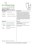
4103-TRM, 4105-TRM, 4106-TRM
Naru™ Trim Series
Operation & Maintenance Manual
Model Numbers
Specifications
4103-TRM
Hand Shower Trim
4105-TRM
Shower Trim with Hand Shower
4106-TRM
Tub/Shower Trim with Hand
Shower
Modifications
Tub/shower trim with hand shower and lever handle
includes wall connection, cradle for hand shower
mounting, in-line vacuum breaker, flexible metal hose,
non-diverter tub spout, 3 mode hand shower and
3 mode showerhead with standard 2.5 gpm (9.5 L/min)
flow restrictor. Shower trim with hand shower and lever
handle includes all of the above less non-diverter tub
spout. Valve trim with hand shower and lever handle
includes all of the above less non-diverter tub spout and
3 mode showerhead. Components made from metal and
nonmetallic materials plated in standard polished
chrome finish.
Compliance
-1.5 1.5 gpm (5.7 L/min) flow restrictor
-2.0 2.0 gpm (7.6 L/min) flow restrictor
-412HSB
30" slide bar in place of wall cradle on
hand shower units
-PNL
Polished nickel finish
-STN
Satin nickel finish
-ASME A112.18.1; CSA B125.1
c
Warranty
Limited Lifetime - to the original end purchaser in
consumer installations.
5 Years - for commercial installations.
Refer to www.symmons.com/warranty for complete
warranty information.
Note: Append appropriate -suffix to model number.
Symmons Industries, Inc. ■ 31 Brooks Drive ■ Braintree, MA 02184 ■ (800)796-6667 ■ Fax: (800)961-9621
©2014 Symmons Industries, Inc.■ www.symmons.com ■ [email protected] ■ ZV-3051 REV 0 09/25/14
Dimensions
Measurements
A
B
D
C
F
E
J
H
G
I
N
M
L
K
O
R
P
Q
S
Floor
A
Ø 2 1/4", 57 mm
B
8 1/4", 210 mm
C
Ø 2 1/4", 57 mm
D
Female 1/2" IPS thread must
be recessed 7/8" from finished
wall
E
6", 152 mm right or left
F
77", 1956 mm
G
Ø 7 1/2", 191 mm
H
Ø 5", 127 mm
I
8", 203 mm
J
4 3/4", 121 mm (4106-TRM)
4 7/8", 124 mm (4105-TRM)
K
2 1/8", 54 mm
L
32", 813 mm (4106-TRM)
45", 1143 mm
(4103-TRM, 4105-TRM)
M
12", 305 mm
N
2 1/4", 57 mm
O
3", 76 mm
P
1/2" NPT
Q
1/2", 13 mm
R
(Rough in)
2 3/8" ± 1/2", 60 mm ± 13 mm
S
7 1/8", 181 mm
Notes:
1) All dimensions measured from nominal rough-in (see R as reference).
2) Dimensions are subject to change without notice.
2
Symmons Industries, Inc. ■ 31 Brooks Drive ■ Braintree, MA 02184 ■ (800)796-6667 ■ Fax: (800)961-9621
©2014 Symmons Industries, Inc.■ www.symmons.com ■ [email protected] ■ ZV-3051 REV 0 09/25/14
Parts Breakdown
Replacement Parts
C
F
E
B
A
N
M
D
O
K
I
J
X
H
T
V
P
L
U
G
Q
W
R
Y
S
Z
Item
Description
Part Number
A
Z
Vacuum Breaker
60" Hose
EF-104
B
C
Wall Elbow
Wall Elbow Flange
T-444-KIT
D
Showerhead
412SH
E
F
Shower Arm
Shower Arm Flange
300
G
H
Diverter Handle
Set Screw
LLD-102
I
Diverter Dome Cover
LLD-101
J
K
L
Diverter Escutcheon
Mounting Screws
Mounting Plate
T-416A
M
N
O
P
Q
Cradle Mount
Cradle Mounting Screws
Washer
Cradle Arm
Set Screw
T-545
R
S
Shower Handle
Set Screw
T-567
T
Shower Dome Cover
T-544
U
V
W
Shower Escutcheon
Mounting Screws
Mounting Plate
T-273-NS-K002
X
Hand Shower
412W
Y
Tub Spout
412TS
Notes:
1) Append -PNL to part number for polished nickel
finish; -STN for satin nickel.
2) Append -1.5 or -2.0 to showerhead or hand shower
for low flow.
Required for Installation
Adjustable wrench
Phillips head screwdriver
Allen wrench (1/8")
Plumber tape
3
Symmons Industries, Inc. ■ 31 Brooks Drive ■ Braintree, MA 02184 ■ (800)796-6667 ■ Fax: (800)961-9621
©2014 Symmons Industries, Inc.■ www.symmons.com ■ [email protected] ■ ZV-3051 REV 0 09/25/14
Installation
Note:
For valve body installation, please
see valve body installation guides.
W
U
G
H
Note: Tabs should snap into place.
1
1
4) Install shower dome cover (T)
and diverter dome cover (I) to
valves by turning clockwise.
K
5) Install diverter handle (G)
(4105-TRM and 4106-TRM only)
and shower handle (R) to valves.
Secure handles by tightening set
screws (H, S).
1
1) Install small plastic mounting
plate (L) to diverter valve
(4106-TRM diverter valve =
4-460E-BODY, 4105-TRM diverter
valve = 4-458E-BODY) and large
plastic mounting plate (W) to
shower valve (4000-BODY).
Secure small plasting mounting
plate with two screws (K) and large
plastic mounting screws with two
screws (V).
3) Attach shower escutcheon (U) to
large plastic mounting plate (W).
R
L
S
2
I
W
1
1
6) Install tub spout (Y) to pipe fitting.
Turn clockwise to secure.
1
2
V
1
2) Attach diverter escutcheon (J) to
small plastic mounting plate (L).
2
Y
T
2
7) Install wall elbow (B) and flange (C)
to recessed pipe fitting. Turn elbow
clockwise to tighten
J
L
1
Note: Tabs should snap into place.
2
C
B
4
Symmons Industries, Inc. ■ 31 Brooks Drive ■ Braintree, MA 02184 ■ (800)796-6667 ■ Fax: (800)961-9621
©2014 Symmons Industries, Inc.■ www.symmons.com ■ [email protected] ■ ZV-3051 REV 0 09/25/14
Installation
8) Press tab to remove mounting
plate (M2) from cradle mount
cover (M1).
10) Install mounting plate (M2).
Secure with two screws (N).
Replace cradle mount cover (M1).
1
1
M2
13) Install shower head (D) to shower
arm (E) turning clockwise to
tighten.
N
M2
2
E
1
M2
2
M1
2
D
3
M1
Note: Mounting plate (M2) center
tabs must be horizontal for removal.
9) Place mounting plate (M2) in
position, mark and drill 1/8" pilot
holes into stud.
Note: Mounting plate (M2) center
tabs must be horizontal for
installation.
1
11) Attach cradle arm (P) and
washer (O) to cradle mount (M).
Secure with set screw (Q).
M2
2
14) Attach large end of hand
shower hose (Z) to hand
shower head (X). Attach small
end of hand shower hose (Z)
and gasket to in-line vacuum
breaker (A). Connect in-line
vacuum breaker to wall
elbow (B). Turn clockwise
to tighten.
M
X
1
2
O
Option: Place mounting plate (M2) in
position, mark and drill 3/16" holes
into wall. Install anchors.
1
M2
2
P
Q
1
Z
12) Attach shower arm (E) and
flange (F) to vertical shower pipe
turning clockwise to tighten.
B
3
A
1
3
2
2
Z
F
E
5
Symmons Industries, Inc. ■ 31 Brooks Drive ■ Braintree, MA 02184 ■ (800)796-6667 ■ Fax: (800)961-9621
©2014 Symmons Industries, Inc.■ www.symmons.com ■ [email protected] ■ ZV-3051 REV 0 09/25/14
4
Operation
Diverter Control
Temperature Control
1) Turn shower handle counterclockwise approximately
1/4 turn to put valve in cold position.
1) D
iverter handle facing straight down is for diverter
function 1.
2) 4
130-TRM & 4105-TMRM: Turn diverter handle
counterclockwise one full revolution for diverter
function 2.
2) T
urn shower handle counterclockwise approximately
1/2 turn to put valve in warm position.
4106-TRM: Turn diverter handle counterclockwise 1/4
turn for diverter function 2.
5205-TRM
3) T
urn shower handle counterclockwise approximately
3/4 turn to put valve in hot position.
5206-TRM
3) 4106-TRM: Turn diverter handle counterclockwise 3/4
turn for diverter function 3.
Care and Cleaning
1) Clean finished trim area with a soft cloth using mild soap and water or a non-abrasive cleaner and then quickly rinse
with water.
Troubleshooting Chart
6
Problem
Cause
Solution
Finish is spotting.
Elements in water supply may cause
water staining on finish.
Clean finished trim area with a soft
cloth using mild soap and water or a
non-abrasive cleaner and then
quickly rinse with water.
Symmons Industries, Inc. ■ 31 Brooks Drive ■ Braintree, MA 02184 ■ (800)796-6667 ■ Fax: (800)961-9621
©2014 Symmons Industries, Inc.■ www.symmons.com ■ [email protected] ■ ZV-3051 REV 0 09/25/14