1
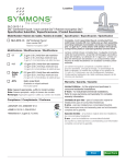
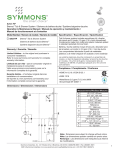
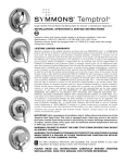
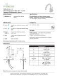
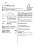
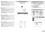
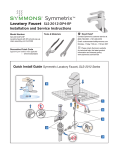
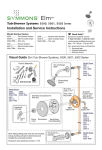
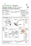
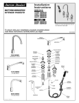
3603-H321-V-TRM, 3605-H321-V-TRM, 3606-H321-V-TRM
Duro™ Trim Series
Operation & Maintenance Manual
Model Numbers
3603-H321-V-TRM
Valve Trim with Hand Shower
3605-H321-V-TRM
Shower Trim with Hand Shower
3606-H321-V-TRM
Tub/Shower Trim with Hand Shower
Options/Modifications
-1.5
1.5 gpm (5.7 L/min) flow restrictor
Specification
Tub/shower trim with hand shower and lever handle
includes wall connection, 30” slide bar, in-line vacuum
breaker, flexible metal hose, non-diverter tub spout,
1 mode hand shower and 1 mode showerhead with
standard 2.5 gpm (9.5 L/min) flow restrictor. Shower
trim with hand shower and lever handle includes all of
the above less non-diverter tub spout. Valve trim with
hand shower and lever handle includes all of the above
less non-diverter tub spout and 1 mode showerhead.
Components made from metal and nonmetallic
materials plated in standard polished chrome finish.
-2.0
2.0 gpm (7.6 L/min) flow restrictor
-LW
Wide lever handle (chrome finish only)
-SS
Slip spout on any tub/shower unit
Compliance
-ASME A112.18.1/CSA B125.1
Warranty
Limited Lifetime - to the original end purchaser in
consumer/residential installations.
5 Years - for industrial/commercial installations.
Refer to www.symmons.com/warranty for complete
warranty information.
Note: Append appropriate -suffix to model number.
Dimensions
A
A
B
C
B
D
D
E
C
E
F
G
H
I
J
F
K
G
L
M
N
I
O
H
M
L
K
J
Floor
P
Q
R
N
P
R
Q
Notes:
1) All dimensions measured from nominal rough-in (see O as reference).
2) Dimensions subject to change without notice.
2
O
Measurements
Ø 2 1/4”, 57 mm
5 7/8”, 149 mm
6”, 152 mm right or left
Male 1/2” NPT thread must
be recessed 1/4” from
finished wall
Ref. 77”, 1956 mm
4 7/8”, 123 mm
5”, 127 mm
7 1/2”, 191 mm
10”, 254 mm
Ø 2 1/2”, 64 mm
(3606)
Ref. 32”, 813 mm
(3603, 3605)
Ref. 42”, 1067 mm
12”, 305 mm
3 3/16”, 81 mm
3 7/16”, 87 mm
Rough-in
2 3/8” ± 1/2”, 60 mm ± 13 mm
5 1/4”, 133 mm
7”, 178 mm
1/2” NPT
Parts Breakdown
Replacement Parts
B
D
C
A
E
G
F
H
S
K
I
J
P
L
G
M
S
J
Description
A
Q
B
I
N
O
P
C
D
E
F*
G
H
S
G
L*
M
S
J
K
R
In-line Vacuum
Breaker & 60” Hose
Wall Elbow
Hand Shower
Slide Bar
Assembly
Shower Arm
Flange
Showerhead
Diverter Escutcheon
Screws
Mounting Plate
Gasket
Screws
Escutcheon
Mounting Plate
Gasket
Handle Assembly
Dome Cover
Tub Spout
Part Number
EF-104
EF-105
EF-100
SC-115
300S
362SH
T-525-NS
T-470-NS-K009
T-617
RTS-037
067
Notes:
1) Append -STN to part number for Satin Nickel finish.
2) Append -1.5 or -2.0 to showerhead or hand
shower for low flow.
O
K
Item
Tools Required for Installation
N
Adjustable
wrench
Q
Allen wrench
(1/8”)
R
Phillips head
screwdriver
Plumber tape
*Note: Apply a bead of silicone around the perimeter of the escutcheons
after installing trim flush with wall. Leave opening on bottom of
escutcheons for weep hole.
Power drill
Silicone
3
Installation
Note:
For valve body installation, please
see valve body installation guides.
5) Install diverter handle (3605 and
3606 only) (J) and shower
handle (J) to valves. Secure
handles by tightening set screws.
M
1
1) Install small plastic mounting
plate (H) to diverter valve (3506
diverter valve = 4-460E-BODY,
3505 diverter valve =
4-458E-BODY) and large plastic
mounting plate (M) to shower valve
(4000-BODY). Secure each with
two screws (G).
3) A
ttach shower escutcheon (L) to
large plastic mounting plate (M).
L
J
Note: Tabs should snap into place.
1
G
1
4) Install dome covers (K) to valves by
turning clockwise.
H
J
M
2
K
1
1
Note: Handles should be facing the
6 o'clock position.
2
G
6) Install tub spout (R) to stub out
pipe. Turn clockwise to secure.
1
2) Attach diverter escutcheon (F) to
small plastic mounting plate (H).
K
F
1
2
R
H
Note: Tabs should snap into place.
4
2
Installation
7a) D
ry Wall Option: Remove upper
and lower caps (N) from slide bar
brackets. Place slide bar (P) into
desired position. Using brackets
as a guide, carefully drill 3/16"
holes into wall. Remove slide bar
and install anchors.
7b) Stud Option: Remove upper and
lower caps (N) from slide bar
brackets. Place slide bar (P) into
desired position. Using brackets
as a guide, carefully drill 1/8"
pilot holes into stud.
8) With slide bar (P) in position,
secure to wall using screws (O).
Replace upper and lower caps (N)
onto slide bar brackets.
N
2
N
O
1
N
1
2
4
2
P
P
P
P
2
2
N
2
N
1
N
1
4
1
3
3
Notes: Make sure that slide bar
holes and bracket holes are aligned
before drilling. Before drilling bottom
hole, make sure slide bar is plumb.
Notes: Make sure that slide bar holes
and bracket holes are aligned before
drilling. Before drilling bottom hole,
make sure slide bar is plumb.
5
Installation
9) Install wall elbow (B) to stub
out pipe. Tighten set screw
to secure.
11) Install showerhead (E) to shower
arm (C). Turn clockwise to
tighten.
1
B
12) A
ttach large end of hand shower
hose (Q) to hand shower wand
(I). Attach small end of hand
shower hose (Q) to in-line
vacuum breaker (A). Connect inline vacuum breaker to wall
elbow (B). Turn clockwise to
tighten.
C
1
I
E
2
2
1
2
Q
10) Attach shower arm (C) and
flange (D) to vertical shower pipe
turning clockwise to tighten.
B
3
A
1
Q
2
D
C
6
4
Operation & Maintenance
Temperature Control
Diverter Control
1) Turn shower handle counterclockwise approximately
1/4 turn to put valve in cold position.
2) Turn shower handle counterclockwise approximately
1/2 turn to put valve in warm position.
1) D
iverter handle facing straight down is for diverter
function 1.
2) 3
605: Turn diverter handle counterclockwise one full
revolution for diverter function 2.
606: Turn diverter handle counterclockwise 1/4 turn
3
for diverter function 2.
3605-H321-V-CYL-B-TRM
3606-H321-V-CYL-B-TRM
3) Turn shower handle counterclockwise approximately
3/4 turn to put valve in hot position.
3) 3606-TRM: Turn diverter handle counterclockwise 3/4
turn for diverter function 3.
Troubleshooting Chart
Finish is spotting.
Elements in water supply may cause
water staining on finish.
Clean finished trim area with a soft
cloth using mild soap and water or a
non-abrasive cleaner and then quickly
rinse with water.
Symmons Industries, Inc. ■ 31 Brooks Drive ■ Braintree, MA 02184 ■ Phone: (800) 796-6667 ■ Fax: (800) 961-9621
Copyright © 2015 Symmons Industries, Inc. ■ www.symmons.com ■ [email protected] ■ ZV-3017 REV 0 ■ 100314