1
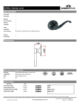
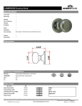
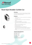
R
Keypad Lock
Installation Instructions
WWW.TODAYSDESIGNHOUSE.COM
Customer Service:1-800-558-8700
R
KEYPAD LOCK
STOP! Please read instructions before removing
Design House Keypad lock from packaging.
Tools Needed for Installation
Phillips
Screwdriver
Drill
Angle Ruler
Flathead
Screwdriver
Lead Pencil
Keypad Lever Entry
Wrench
(Provided with lock)
Chisel
Hammer
Stiletto
(For door hole2-1/8)
Removing Keypad Lock from packaging
Keypad Deadbolt Entry
1. Unscrew and remove Cover Loop and Plastic Gasket from Interior Panel with provided
tool Wrench.
2. Remove Interior Cover Plate screws (4) to expose Battery Box.
3. Unscrew and remove two mounting screws.
4. Interior and Exterior can be removed from the styrofoam packaging.
5. Proceed with installation of Keypad Lock.
Page.2
R
KEYPAD LOCK
Cover loop
Interior cover plate
Interior cover plate
Interior panel
Interior panel
Installation Instructions
B
B
power wire
power wire
C
1.Use template [provided] to prepare door.
C
4*35mm screw
4*35mm screw
Spindle
Fig. B
Keypad Lever Entry
Spindle
Keypad Deadbolt Entry
Exterior Panel
Exterior Panel
Packing List
B
C
Exterior Panel
Plastic Insert
4x2 (4x50MM)
screws
Interior Panel
Interior
Cover Plate
Strike Plate
Single Latch
3.5x3/4 (3.5x20MM)
screws
4x1.38
(4x35MM) screws
Keyhole/
Cylinder Cover
Cylinder
Cover Remover
Fig.
Manual Override
Keys
Door Preparation
Drilling Template
Page.3
Wrench (For Lever Entry Lock)
Page.4
R
KEYPAD LOCK
2. Drill and prepare the doorframe for the Plastic Insert and Strike Plate making
sure the holes are level and a direct match for the door lock drilling (See Fig. A).
9. Feed Cover Loop and plastic gasket ring over the interior handle. Screw Cover Ring
tightly to secure the interior assembly.(Lever Entry Only)
1-3/4
(44mm)
Attach the Interior Cover onto the Interior Panel and fix them with two (3x10mm)
screws on both sides of Interior Cover.See Fig.2. (Deadbolt Entry Only)
1-1/8
(28mm)
2-1/4
(57mm)
Cover loop
Interior cover plate
Interior cover plate
Interior panel
Interior panel
1/2
(13mm)
Fig.A.
B
B
3. Insert latch to prepared door and attached with two (3.5x3/4" / 3.5x20MM)
screws. See Fig. 1.
power wire
power wire
C
C
4*35mm screw
4*35mm screw
Door panel
Door panel
Spindle
Fig. 2
Deadbolt
Regular Latch
3.5x20mm screw
Keypad Lever Entry
Spindle
Exterior Panel
Keypad Deadbolt Entry
10. Place Plastic Insert into prepared hole on door frame. Attach Strike Plate
with two self-tapping screws.
11. Verify that the Door Latch engages with the Strike Plate on the doorframe.
3.5x20mm screw
3.5x20mm screw
3.5x20mm screw
Fig.1
Door frame
4. Install 4 (AA) alkaline batteries in the Battery Box on the Interior Panel.
5. Feed the power wire from the Exterior Panel (with keypad) through the door hole (A)
Plastic Insert
and latch (see Fig. 2). Connect the power wire to the battery box.
Strike Plate
6. Attach the Exterior Panel making sure the lock Spindle is squarely inserted into mounting plate on Interior Panel through door hole (A). Be sure to secure the metal panels
to the inner edges of the rubber gaskets for a sealed installation on both the interior
and exterior sides.
7. Attach the Exterior Panel and the Interior Panel with two (4x1-3/8 / 4x35MM) or
Fig.3
(4x1.97" / 4x50MM) screws depending on different door thicknesses.
8. Attach the Interior Cover Plate over the Battery Box and Interior Panel.
Page.5
Page.6
Exterior Panel
R
KEYPAD LOCK
Operating and Programming Instructions
There are two ways to open Design House Keypad Locks.
- Enter a valid 6-digit password; the green indicator light will go ON; use the lever or knob
to open the latch within 5 seconds.
- Manual override keys (for emergency use).
Adding a User Password
Press: ## + Master Password + #** + 3-digit User Number + 6-digit User Password + 6-digit User
Password Example: To add User Number 005 with User Password 123456, press: ## + Master
Password + #** + 005 + 123456 + 123456
Deleting a User Password
Press: ## + Master Password + *#* + 3-digit User Number + 3-digit User Number
Changing a User Password
Press: ## + User Password to be changed + *** + New User Password + New User Password
IMPORTANT
Enabling Passage Function (Press any key to open the door)
1. The factory set Master Code is 111111 . Pl ease change th e Master Password to a new
6-digit Master Code on the initial use.
2. The Design House Keypad Entry Lock holds 300 User Passwords.
3. The Design House Keypad Entry Lock makes several sounds:
- Three short beeps indicate an incorrectly keyed code. Door will not unlock.
- One long beep indicates a correctly keyed code. Open the latch within 5 seconds to open
the door.
Press: ## + Master Password + ### + ###
Disabling Passage Function
(keeps door in LOCKED state; opened with valid User Passwords)
Press: ## + Master Password + ### + ###
Code Definitions
Master Code = 6 digits. Required for making changes and additions to all codes. Factory
set Master must be changed the 1st time the lock is used for increased security.
Property owner/manager should keep this information confidential.
User Number = 3 digits. Identifies the user. Property owner/manager should keep a log of
User Numbers.
User Password = 6 digits. User enters this code on the keypad to gain entry into building.
USERS-To Open the Lock
Press: User Password. After green light goes ON, press lever or rotate knob to open
door within 5 seconds.
In case of loss of user records or other need to RESET all
passwords
Dismantle the Keypad Lock assembly. Press the RESET button on the inside of the
Exterior Panel.
Lock will return to factory set Master Code. Change to new Master Code. Program all
new User Numbers and User Passwords as listed above.
Programming/Changing Codes
Changing the Master Code (initial use)
Press: ## + Factory Set Master Password + *** + New Master Password + New Master
Password
Page.7
Page.8