1
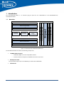
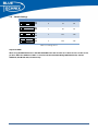
Hardware User Manual EXP-BF548-EXP V1.x Contact Bluetechnix Mechatronische Systeme GmbH Waidhausenstr. 3/19 A-1140 Vienna AUSTRIA/EUROPE [email protected] http://www.bluetechnix.com Document No.: 100-2254-1.0 Document Revision 2 2010-07-13 EXT‐BF548‐EXP‐Hardware User Manual 1 Table of Contents 1 2 Introduction .................................................................................................................................................................................. 7 1.1 Overview ............................................................................................................................................................................... 7 1.2 Switch Settings ................................................................................................................................................................... 8 Schematic....................................................................................................................................................................................... 9 2.1 Mechanical Outline ........................................................................................................................................................ 10 3 Anomalies ................................................................................................................................................................................... 11 4 Document Revision History .................................................................................................................................................. 11 5 A List of Figures and Tables .................................................................................................................................................. 11 EXT‐BF548‐EXP‐Hardware User Manual 2 Edition 2008-09 © Bluetechnix Mechatronische Systeme GmbH 2008 All Rights Reserved. The information herein is given to describe certain components and shall not be considered as a guarantee of characteristics. Terms of delivery and rights of technical change reserved. We hereby disclaim any warranties, including but not limited to warranties of non-infringement, regarding circuits, descriptions and charts stated herein. Bluetechnix makes and you receive no warranties or conditions, express, implied, statutory or in any communication with you. Bluetechnix specifically disclaims any implied warranty of merchantability or fitness for a particular purpose. Bluetechnix takes no liability for any damages and errors causing of the usage of this board. The user of this board is responsible by himself for the functionality of his application. He is allowed to use the board only if he has the qualification. More information is found in the General Terms and Conditions (AGB). Information For further information on technology, delivery terms and conditions and prices please contact Bluetechnix (http://www.bluetechnix.com). Warning Due to technical requirements components may contain dangerous substances. The Core Modules and development systems contain ESD (electrostatic discharge) sensitive devices. Electro-static charges readily accumulate on the human body and equipment and can discharge without detection. Permanent damage may occur on devices subjected to high-energy discharges. Proper ESD precautions are recommended to avoid performance degradation or loss of functionality. Unused Core Modules and Development Boards should be stored in the protective shipping EXT‐BF548‐EXP‐Hardware User Manual 3 BLACKFIN Products Core Modules: CM-BF533: Blackfin Processor Module powered by Analog Devices' single core ADSP-BF533 processor; up to 600MHz, 32MB SDRAM, 2MB flash, 2x60 pin expansion connectors and a size of 36.5x31.5mm. CM-BF537E: Blackfin Processor Module powered by Analog Devices' single core ADSP-BF537 processor; up to 600MHz, 32MB SDRAM, 4MB flash, integrated TP10/100 Ethernet physical transceiver, 2x60 pin expansion connectors and a size of 36.5x31.5mm. CM-BF537U: Blackfin Processor Module powered by Analog Devices' single core ADSP-BF537 processor; up to 600MHz, 32MB SDRAM, 4MB flash, integrated USB 2.0 Device, 2x60 pin expansion connectors and a size of 36.5x31.5mm. TCM-BF537: Blackfin Processor Module powered by Analog Devices' single core ADSP-BF537 processor; up to 500MHz, 32MB SDRAM, 8MB flash, a size of 28x28mm, 2x60 pin expansion connectors, Ball Grid Array or Border Pads for reflow soldering, industrial temperature range -40°C to +85°C. CM-BF561: Blackfin Processor Module powered by Analog Devices' dual core ADSP-BF561 processor; up to 2x 600MHz, 64MB SDRAM, 8MB flash, 2x60 pin expansion connectors and a size of 36.5x31.5mm. CM-BF527: The new Blackfin Processor Module is powered by Analog Devices' single core ADSP-BF527 processor; key features are USB OTG 2.0 and Ethernet. The 2x60 pin expansion connectors are backwards compatible with other Core Modules. CM-BF548: The new Blackfin Processor Module is powered by Analog Devices' single core ADSP-BF548 processor; key features are 64MB DDR SD-RAM 2x100 pin expansion connectors. TCM-BF518: The new Core Module CM-BF518 is powered by Analog Devices' single core ADSP-BF518 processor; up to 400MHz, 32MB SDRAM, up to 8MB flash. The 2x60 pin expansion connectors are backwards compatible with other Core Modules. Development Boards: EVAL-BF5xx: Low cost Blackfin processor Evaluation Board with one socket for any Bluetechnix Blackfin Core Module. Additional interfaces are available, e.g. an SDCard. DEV-BF5xxDA-Lite: Get ready to program and debug Bluetechnix Core Modules with this tiny development platform including an USB-Based Debug Agent. The DEV-BF5xxDALite is a low cost starter development system including a VDSP++ Evaluation Software License. DEV-BF548-Lite: Low-cost development board with one socket for Bluetechnix CM-BF548 Core Module. Additional interfaces are available, e.g. an SD-Card, USB and Ethernet. EXT‐BF548‐EXP‐Hardware User Manual 4 DEV-BF548DA-Lite: Get ready to program and debug Bluetechnix CM-BF548 Core Module with this tiny development platform including an USB-Based Debug Agent. The DEVBF548DA-Lite is a low-cost starter development system including a VDSP++ Evaluation Software License. EXT-Boards: The following Extender Boards are available: EXT-BF5xx-AUDIO, EXT-BF5xxVIDEO, EXT-BF5xx-CAM, EXT-BF5xx-EXP-TR, EXT-BF5xx-USB-ETH2, EXT-BF5xxAD/DA, EXT-BF548-EXP and EXT-BF518-ETH. Furthermore, we offer the development of customized extender boards for our customers. Software Support: BLACKSheep: The BLACKSheep VDK is a multithreaded framework for the Blackfin processor family from Analog Devices that includes driver support for a variety of hardware extensions. It is based on the real-time VDK kernel included within the VDSP++ development environment. LabVIEW: LabVIEW embedded support for Bluetechnix Core Modules is done by SchmidEngineering AG: http://www.schmid-engineering.ch uClinux: All the Core Modules are fully supported by uClinux. The required boot loader and uClinux can be downloaded from: http://blackfin.uClinux.org. Upcoming Products and Software Releases: Keep up-to-date with all the changes to the Bluetechnix product line and software updates at: http://www.bluetechnix.com . Software Support: BLACKSheep: The BLACKSheep VDK is a multithreaded framework for the Blackfin processor family from Analog Devices that includes driver support for a variety of hardware extensions. It is based on the real-time VDK kernel included within the VDSP++ development environment. LabVIEW: LabVIEW embedded support for Bluetechnix Core Modules is done by SchmidEngineering AG: http://www.schmid-engineering.ch uClinux: All the Core Modules are fully supported by uClinux. The required boot loader and uClinux can be downloaded from: http://blackfin.uClinux.org. Upcoming Products and Software Releases: Keep up-to-date with all the changes to the Bluetechnix product line and software updates at: http://www.bluetechnix.com EXT‐BF548‐EXP‐Hardware User Manual 5 BLACKFIN Design Service Based on more than five years of experience with Blackfin, Bluetechnix offers development assistance as well as custom design services and software development. EXT‐BF548‐EXP‐Hardware User Manual 6 1 Introduction The EXT-BF548-EXP Board is an extender plug-on board for the DEV-BF548-Lite and DEV-BF548DA-Lite Development Boards. 1.1 Overview 30x 2.54mm pitch solder holes 60 Pin Connector B 30x 2.54mm pitch solder holes SUB-D9 Connector ADM3202 Level Shifter 8-Way DIPSwitch UART Multiplexer 30x 2.54mm pitch solder holes 60 Pin Connector A 30x 2.54mm pitch solder holes Figure 1-1: Overview of the EXT-BF548-EXP Board The EXT-BF548-EXP Board includes the following components: 1 SUB-D9 UART Connector o ADM3202 1Mbps transceiver compatible to RS232 o 8 Bit DIP-Switch to multiplex the 4 UARTS to the RS232 transceiver 200 Expansion Pads The pad number equals to the Core Module pin number of the CM-BF548. 8 Power Pads EXT‐BF548‐EXP‐Hardware User Manual 7 1.2 Switch Settings Switch Setting Blackfin UART No. Rx‐Pin No. TX Pin No. 0 23 38 1 26 19 2 141 140 3 143 142 Table 1-1: Settings for S1 Important NOTE: When using the DEV-BF548-Lite or the DEV-BF548DA-Lite make sure that S3 on these boards is at the correct position. Otherwise UART0 or UART1 is routed to both the USB-UART-Bridge (DEV-BF548-Lite) and the ADM3202 (EXT-BF548-EXP) simultaneously. EXT‐BF548‐EXP‐Hardware User Manual 8 2 Schematic X3 1 2 3 4 5 6 7 8 9 10 11 12 13 14 15 16 X12 2 1 2 1 CON16(1 X18 X20 1 2 3 4 5 6 7 8 9 10 11 12 13 14 15 16 X22 Tx1 Rx0 Tx0 Rx1 29 30 5V0 5V0 CON16(1 61 120 62 119 63 118 64 117 65 116 66 115 67 114 68 113 69 112 70 111 71 110 72 109 73 108 74 107 75 106 76 105 77 104 78 103 79 102 80 101 81 100 82 99 83 98 84 97 85 96 86 95 87 94 88 93 89 92 90 91 A1 A2 A3 A4 A5 A6 A7 A8 A9 A10 A11 A12 A13 A14 A15 PG0 PG1 PH2 PG2 PF0 PF1 PF2 PF3 EXT‐BF548 PF4 PF5 Extender CM‐BF548 bottom PF6 PF7 PF8 PF9 PF10 PF11 PF12 PF13 PF14 PF15 3V3 GND AMS2 AMS1 ARE AWE AOE NMI RESET D0 D1 D2 D3 D4 D5 D6 D7 D8 D9 D10 D11 D12 D13 D14 D15 Vin Vin 3.3V GND PC7 PC4 PC6 PC5 PC3 PC0 PC2 PC1 CLKOUT PE14 PE15 PH3 PA13 PA9 PA5 PA1 3V3 GND 3V3 GND PD0 PD1 PD2 PD3 PD4 PD5 PD6 PD7 PD8 PD9 PD10 PD11 PD12 PD13 PD14 PD15 PH0 PE13 PE12 PE11 PB11 PB10 PB9 PB8 PE8 PE7 PB13 PB14 PB12 ABE0 PH1 ABE1 ARDY AMS3 PH4 PH7 1 2 3 4 5 6 7 8 9 10 11 12 13 14 15 16 X17 X6 2 1 2 1 X19 3.3V X21 X7 1 2 CON16(1 X14 X23 1 2 3 4 5 6 7 8 9 10 11 12 13 14 15 16 121 122 123 124 125 126 127 128 129 130 131 132 133 134 135 136 137 138 139 140 141 142 143 144 145 146 147 148 149 150 151 152 153 154 155 156 157 158 159 160 1 X16 1 2 3 4 5 6 7 8 9 10 5.0V 2 1 Vin 2 CON16(1 3 4 5 6 7 8 9 10 11 12 13 14 15 16 3.3V GND CON10(1‐2)‐2.54 X24 CON16(1 X29 X26 2 1 2 1 3.3V X8 X5B 1 2 3 4 5 6 7 8 9 10 11 12 13 14 15 16 X11 X10 CON16(1 GND 2 1 GND X9 1 2 3 4 5 6 7 8 9 10 11 12 13 14 15 16 2 1 Tx2 Rx2 Tx3 Rx3 1 2 1 2 GNDGND 3.3V GND PJ13 PJ12 PJ11 PJ10 PJ9 PJ8 PJ7 PJ6 PJ5 PJ4 PJ3 PJ2 PJ1 GND PB0 PB1 PB2 PB3 PB4 PB5 PB6 PB7 GND PA0 PA2 PA3 PA4 PA6 PA7 PA8 PA10 PA11 PA12 PA14 PA15 GND GND 3V3 3V3 GND CLKBUF GND EXT_WAKEUP ATAPI_PDIAG PH5 PH6 PC13 PC12 PC11 PC10 PC9 PC8 GND PE10 PE9 PE6 PE5 PE4 PE3 PE2 PE1 PE0 GND PG15 PG14 PG13 PG12 PG11 PG10 PG9 PG8 PG7 PG6 PG5 PG4 PG3 GND Vin 5V0 200 199 198 197 196 195 194 193 192 191 190 189 188 187 186 185 184 183 182 181 180 179 178 177 176 175 174 173 172 171 170 169 168 167 166 165 164 163 162 161 1 2 3 4 5 6 7 8 9 10 11 12 13 14 15 16 X15 1 2 CON16(1 3 4 5 6 7 8 9 10 11 12 13 14 15 16 2 1 2 1 2 1 X25 CON16(1 X27 X28 Vin 5.0V Extender CM‐BF548 bottom CON16(1 31 32 3.3V CON16(1 GND 1 60 2 59 3 58 4 57 5 56 6 55 7 54 8 53 9 52 10 51 11 50 12 49 13 48 14 47 15 46 16 45 17 44 18 43 19 42 20 41 21 40 22 39 23 38 24 37 25 36 26 35 27 34 28 33 X13 X4 X5A 1 2 3 4 5 6 7 8 9 10 11 12 13 14 15 16 5.0V Vin C1 3.3V C3 100n V+ 2 V‐ 6 100n C5 GND S1 Tx0 Tx1 Tx2 Tx3 Rx0 Rx1 Rx2 Rx3 1 2 3 4 5 6 7 8 16 15 14 13 12 11 10 9 100n 1 2 U1 16 GND GND 15 T1IN 11 10 R1OUT 12 9 X2 C2 Vcc RS232 C1+ V+ C1- V- C2+ GND C2- T1IN T2IN R1OUT R2OUT T1OUT T2OUT R1IN R2IN 1 C1+ 3 C1‐ 4 C2+ 5 C2‐ 100n C4 X1 100n 14 7 RTS TXD 13 8 CTS RXD GND ADM3202 5 9 4 8 3 7 2 6 1 GND RI DTR CTS TxD RTS RxD DSR DCD 5 GND 11 8 CTS auf PC 3 TXD auf PC 7 RTS auf PC GND 2 RXD auf PC 10 PC Pinout 9Pol RS232_male RS232_m DIPSW8 Figure 2-1: Experimental Board Schematic EXT‐BF548‐EXP‐Hardware User Manual 9 2.1 Mechanical Outline 2 2 2 2 1 1 1 1 xx2 xx1 9 8 7 6 10 16 15 14 13 12 11 11 5 1 16 2 15 3 14 4 13 5 12 4 1 10 9 3 2 5 4 16 15 14 13 12 11 10 9 8 7 6 5 4 3 2 1 1 2 1 2 16 15 14 13 12 11 10 9 8 7 6 5 4 3 1 7 6 1 2 1 2 1 8 2 6 11 7 10 8 9 2 2 1 1 2 3 2 1 10 9 8 7 6 5 4 3 2 1 16 15 14 13 12 11 10 9 8 7 6 5 4 3 Hole3 Hole2 Hole4 2 1 2 1 1 1 2 Hole1 16 15 14 13 12 11 10 9 8 7 2 4 6 8 10 12 14 16 2 4 6 8 10 12 14 16 1 1 1 6 5 1 3 5 7 9 11 13 15 1 3 5 7 9 11 13 15 2 2 2 4 3 1 2 16 15 14 13 12 11 10 9 8 7 6 5 4 3 2 1 Hole6 Hole5 2 2 1 2 4 6 8 10 12 14 16 2 4 6 8 10 12 14 16 2 2 2 1 3 5 7 9 11 13 15 1 3 5 7 9 11 13 15 1 1 1 xx3 xx4 Figure 2-2: Mechanical Outline – TOP 2 2 2 2 1 1 1 1 xx1 xx2 6 7 8 9 11 10 1 15 16 13 14 2 3 4 5 11 12 1 9 10 2 7 8 5 6 3 4 1 2 2 1 2 15 16 13 14 11 12 9 10 7 8 5 6 3 4 1 2 9 10 7 8 5 6 3 4 1 Hole2 15 16 13 14 11 12 9 10 7 8 5 6 3 Hole3 1 2 15 16 13 14 11 12 9 10 7 8 5 6 3 4 1 2 4 1 2 2 1 Hole1 2 Hole4 1 15 16 13 14 11 12 9 10 7 8 5 6 Hole6 3 4 1 2 1 2 15 16 13 14 11 12 9 10 Hole5 1 1 1 16 14 12 10 8 6 4 2 16 14 12 10 8 6 4 2 7 8 2 2 2 15 13 11 9 7 5 3 1 15 13 11 9 7 5 3 1 5 6 3 4 1 2 2 2 2 16 14 12 10 8 6 4 2 16 14 12 10 8 6 4 2 1 1 1 15 13 11 9 7 5 3 1 15 13 11 9 7 5 3 1 xx4 xx3 Figure 2-3: Mechanical Outline – Bottom EXT‐BF548‐EXP‐Hardware User Manual 10 3 Anomalies For the latest information regarding anomalies for this product, please consult the product home page: http://www.bluetechnix.com/goto/ext-bf548-exp 4 Document Revision History Version Date Document Revision 2 2009-09-30 Important Note updated 1 2008-11-10 Version 1.0 Table 4-1: Revision History 5 A List of Figures and Tables Figure 1-1: Overview of the EXT-BF548-EXP Board ................................................................................................................... 7 Figure 2-1: Experimental Board Schematic .................................................................................................................................. 9 Figure 2-2: Mechanical Outline – TOP......................................................................................................................................... 10 Figure 2-3: Mechanical Outline – Bottom .................................................................................................................................. 10 EXT‐BF548‐EXP‐Hardware User Manual 11