1
Vestil Manufacturing Corporation
2999 North Wayne St., Angola, IN 46703
Ph: (260) 665-7586 • Fax: (260) 665-1339
[email protected] • www.vestil.com
Ergonomic Solutions
Revised 0809
29-126-103
A company dedicated to solving ergonomic and material
handling problems since 1955.
OWNERS
MANUAL
CAR STOP • MODEL CS-33
Contents
Hardware Kits .............................................................. 1
Receiving Instructions ................................................. 1
Warranty ...................................................................... 1
CONCRETE HARDWARE KIT (standard)
The following tools/hardware are required for installing your car
stop.
CS-33-CK KIT INCLUDES:
3 - 1/2” x 6” lag bolt for each hole
3 - 1/2” washers for lag bolts
3 - 1/2” anchor sleeve for each bolt
CUSTOMER SUPPLIES:
1 - High-speed hammer drill 3/4” masonry bit
1 - Impact wrench or heavy ratchet 3/4” socket
ASPHALT HARDWARE KIT
The following tools/hardware are required for installing your car
stop.
CS-AK KIT INCLUDES:
3 - 12” long steel spikes
1 - 72” long pieces of Butyl tape
CUSTOMER SUPPLIES:
1 - Sledge Hammer
RECEIVING INSTRUCTIONS
Every unit is thoroughly tested and inspected prior to
shipment. However, it is possible that the unit may incur damage
during transit. If damage is noticed when unloading, make a note
of it on the BILL OF LADING. Remove all packing and strapping
material, then inspect the unit again for damage. IF DAMAGE IS
EVIDENT, FILE A CLAIM WITH THE CARRIER IMMEDIATELY!
Assembly Instructions................................................... 1
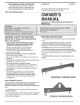
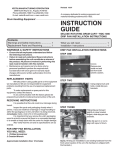
Assembly Drawing ........................................................ 1
2.) Remove the car stop. Using high speed hammer drill
with a 3/4” masonry bit, drill a hole at each marked location
to a depth of 3-1/2” below the road surface.
3.) Insert a anchor sleeve into each hole (large sleeve opening
on top). Tap the sleeves into the holes with a hammer so that
the sleeves are set flush with the surface. Place a washer
over each sleeve hole.
4.) Make sure the substrates are thoroughly clean and dry.
Reposition the car stop in its installation position. Apply firm
hand pressure. Slip a washer onto a lag bolt, insert the
bolt through a predrilled hole in the speed bump, align over
anchor sleeve and tighten the bolt about three-quarter of the
way with the 3/4” socket. Repeat for each hole in the speed
bump. Finish tightening each bolt until just snug. DO NOT
OVER TIGHTEN! Excessive tightening may damage the
car stop and void the product warranty.
ASSEMBLY INSTRUCTIONS
ASPHALT, HIGH USE AREA’S, OR LOCATIONS WITH
TEMPERATURES OVER 110°F
1) Adhere the Butyl tape to the under structure of car stop
length wise.
2) Place car stop in desired position.
3) Insert spike through predrilled hole. DO NOT HOLD SPIKE
WHILE HAMMERING! Drive spike into ground until flush
with car stop.
E
S
P
A
N
O
L
F
R
A
N
Ç
A
I
S
WARRANTY
This product is warranted for 30 DAYS from date of
purchase to be free of manufacturing defects in material and
workmanship. The manufacturer's obligation hereunder is limited
to repairing such products during the warranty period, provided
the product is sent prepaid back to the factory.
This warranty does not cover normal wear of parts or
damage resulting from any of the following: negligent use or
misuse of the product, use or application contrary to installation
instructions, or disassembly, repair or alteration by any person
prior to authorization from a factory representative.
ASSEMBLY INSTRUCTIONS
CONCRETE (standard)
1.) Position the car stop in its intended position and using its
predrilled holes as templates, mark the location of each hole
on the road surface.
E
N
G
L
I
S
H
CAR STOP • MODEL CS-33
Vestil Manufacturing Corporation
2999 North Wayne St., Angola, IN 46703
Ph: (260) 665-7586 • Fax: (260) 665-1339
[email protected] • www.vestil.com
Revisado 0809
29-126-103
Una compañia dedicada a resolver problemas ergonómicos
y de manejo del material desde 1955.
Soluciones Ergonómicas
MANUAL DEL
PROPIETARIO
PARA COCHE • MODELO CS-33
Contenido
Juego de Ferreteria ......................................................... 2
Instrucciones de Recibo .................................................. 2
Garantia .......................................................................... 2
CONCRETO JUEGO DE FERRETERIA
La ferreteria/herramientas siguientes son requeridas para la instalación
de su para coche.
EL JUEGO CS-33-CK INCLUYE:
3 - Pija de 1.27 mm x 152.4 mm para cada perforación
3 - Rondana de 12.7 mm para pija
3 - Ancla de 12.7 mm para cada pija
ASFALTO JUEGO DE FERRETERIA
La ferreteria/herramientas siguientes son requeridas para la instalación
de su tope de velocidad.
EL JUEGO CS-AK INCLUYE:
3 - Barras de acero de 30.48 cm de longitud
1 - Piezas de adhesivo de butyl de 183 cm de longitud
E
S
P
A
N
O
L
EL CLIENTE SUMINISTRA:
1 - Martillo
INSTRUCCIONES DE RECIBO
Cada unidad está inspeccionada a fondo y probada antes del
envio. Aun asi, es posible que la unidad se dañe durante el envio. Si ve
algún daño durante la descarga anótelo en el RECIBO DE ENVIO. Quite
todo el material de empaquetado y las correas, inspeccione por daños.
SI HAY DAÑOS EVIDENTES, ARCHIVE UNA RECLAMACION CON EL
TRANSPORTISTA IMMEDIATAMENTE.
Instrucciones de Ensamble ............................................... 2
Dibujo de Ensamble .......................................................... 2
se abra en la parte superior). Golpee las anclas en los agujeros
con un martillo hasta que las anclas esten a ran de la superficie.
Ponga las rondanas sobre cada agujero.
4.) Asegurese de que las superficies montantes estan limpias y
secas. Reposicione el para coche en la posición de
instalación. Apriete firmemente con la mano. Ponga una
rondana en cada pija, inserte la pija a traves del agujero
pretaladrado en el tope de velocidad, alinie sobre el ancla y
apriete la pija 3/4 de vuelta con una boquilla de 19.05 mm.
Repita en cada agujero del tope de velocidad. Acabe apretando
cada pija firmemente. NO SOBREAPRIETE. Apretando
excesivamente se podria dañar el tope de velocidad y la
garantia se anularia.
INSTRUCCIONES DE ENSAMBLE
ASFALTO, ZONAS DE MUCHO USO, O ZONAS DE MÁS DE 43°C.
1) Use el adhesivo de butyl a lo largo de debajo del para coche.
2) Situe el para coche en la posición deseada.
3) Inserte la barra a través del agujero pre-taladrado. NO
SUJETE LA BARRA MIENTRAS SE ESTE USANDO EL
MARTILLO. Martillee la barra hasta que este a ran del para
coche.
GARANTIA
Este producto está garantizado durante 90 DIAS desde la
fecha de compra de estar libre de defectos de material y mano de obra.
La obligación del fabricante está limitada a reparar tales productos
durante el periodo de garantia, provisto que el producto se envie previo
envio flete pagado a la fábrica.
Esta garantia no cubre el gasto normal de partes o daños que
resulten de lo siguiente: uso negligente o mal uso del producto, uso o
aplicación contraria a las instrucciones de instalación, o desensamble,
reparaciones o alteraciones por cualquier persona antes de la previa
autorización de un representante de la fábrica.
INSTRUCCIONES DE ENSAMBLE
CONCRETO
1.) Coloque el para coche en su posición y usando sus barrenos
pretaladrados como una guía, marque la posición de cada
barreno en la superficie.
2.) Quite el para coche. Usando un roto martillo de alta velocidad
con broca de 19.05 mm para mamposteria taladre un agujero en
cada lugar marcado a una profundidad de 88.9 mm, por debajo
de la superficie.
3.) Inserte un ancla en cada agujero (el lado grande del ancla que
TOPE DE VELOCIDAD • MODELO CS-33
Vestil Manufacturing Corporation
2999 North Wayne St., Angola, IN 46703
Ph: (260) 665-7586 • Fax: (260) 665-1339
[email protected] • www.vestil.com
Solutions Ergonomiques
Révisé 0809
29-126-103
Une compagnie dédiée à résoudre les problèmes
ergonomiques et de prise en charge de matériel depuis
1955.
MANUEL
D’UTILISATION
BLOC D’ ARRÊT POUR AUTOMOBILE
MODÈLE CS-33
Contenu
Table des Matières ........................................ 3
Instructions de Reception .............................. 3
Garantie ........................................................ 3
KIT DE QUINCAILLERIE POUR CIMENT (standard)
Les outils suivants sont nécessaires pour l’installation de bloc d’ arrêt.
LE KIT CS-33-CK INCLUT:
3 - Boulons de 1.27 mm x 15.24 cm pour chaque perforation
3 - Rondelles de 1.27 mm pour cheville
3 - Chevilles de 1.27 mm pour chaque boulon
KIT DE QUINCAILLERIE POUR ASPHALTE
Les outils suivants sont nécessaires pour l’installation de votre
ralentisseur sur asphalte.
LE KIT CS-33-AK INCLUT:
3 - Longues pointes en acier de 30.48 cm
1 - Morceaux de bande adhésive butyl de 183 cm de long
LE CLIENT DOIT SE PROCURER:
1-Marteau de forgeron
INSTRUCTIONS DE RÉCEPTION
Chaque unité est minutieusement testée et inspectée avant
expédition. Toutefois, il est possible que l'unité ait subi des dommages
durant le transport. Si les dommages sont constatés durant le
déchargement, les signaler sur LA FACTURE DE CHARGEMENT.
Retirer le matériel d'empaquetage, puis inspecter l'unité de nouveau
pour tout dommage. Si le dommage est évident, remplir une réclamation
avec le transporteur immédiatement.
GARANITE
Instructions D’assemblage ........................... 3
Shéma d’assemblage ................................... 3
3.) Insérer une cheville dans chaque trou (large ouverture de la
cheville vers le haut) tapoter les poches des chevilles avec un
marteau afin que celles-ci soient au ras de la surface du sol.
Placer une rondelle sur chaque trou de cheville.
4.) S’assurer que les substrats soient bien propres et secs.
Repositionner le bloc d’ arrêt dans sa position d’installation.
Appliquer une ferme pression de la main. Glisser une rondelle
dans le boulon, insérer le boulon dans le trou pré-percé du
bloc d’ arrêtt, l’aligner au dessus de la cheville et serrer le boulon
au trois quart avec une clé de 19.05 mm, Répéter cette opération
pour tous les trous du ralentisseur. Finir de visser tous les
boulons jusqu’ à ce qu’ils soient bien ajustés. NE PAS TROP
VISSER! Une vissage excessif pourrait endommager le
ralentisseur et annuler la garantie.
INSTRUCTIONS D’ASSEMBLAGE
ASPHALTE, AIRES À GRANDE UTILISATION, OU
LOCATIONS DONT LES TEMPÉRATURES DÉPASSENT 43°C
1.) Coller la bande adhésive butyl sur la structure inférieure du
bloc d’ arrêt et sur toute sa longueur.
2.) Placer le bloc d’ arrêt sur la position désirée.
3.) Insérer la pointe d’acier dans le tou pré-percé. NE PAS TENIR
LA POINTE D’ACIER LORS DU MARTELAGE! Enfoncer la
pointe d’acier dans le sol jusqu’ à ce qu’elle soit au ras du
bloc d’ arrêt.
Ce produit est garanti pendant 30 jours à partir de la date
d'achat pour tout défaut de fabrication, en matériel ou en main d'œuvre.
L'obligation du fabricant est limitée à la réparation de tels produits durant
la période de garantie à condition que le produit soit envoyé à la
compagnie frais de port pré-payés.
Cette garantie ne couvre pas les usures normales de pièces
ou des dommages résultant de ce qui suit: Utilisation négligente ou
mauvaise utilisation du produit, utilisation ou applications contraires aux
instructions d'assemblage ou de désassemblage, réparation ou altération
par quiquonque sans autorisation préalable d'un représentant de l'usine.
F
R
A
N
Ç
A
I
S
INSTRUCTIONS D’ASSEMBLAGE
CIMENT
1.) Placer le bloc d’ arrêt dans la position voulue et, en utilisant ses
trous pré-perforés comme des patrons, marquer l’emplacement
de chaque trou sur la surface de la chaussée.
2.) Retirer le bloc d’ arrêt. Avec une perceuse à grande vitesse
munie d’une mèche de 19.05 mm, percer un trou à chaque
endroit marqué sur une profondeur de 19.05 mm en dessous de
la surface d’arrêt.
RALENTISSEUR • MODÈLE CS-33
Material Handling Problem Solvers
Scissor Lift Table
Pallet Server
V
III
IV
Time is money.
Increased productivity
equals greater profitability,
cost minimization and worker
compatibility. Ergonomic
products will assist you
with your production and
safety goals.
High Rise Lift
II
I
X
I
X
I
I
XII
I
I
X
V
VI V
I
I
Mobile Lift & Tilt
Work Stand
Drum Carrier/Rotator
Ground Lift Tilter
Copyright 2004 Vestil Manufacturing Company