1
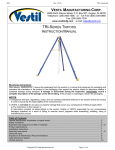
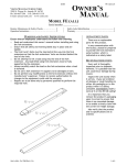
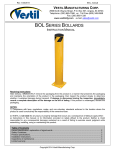
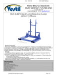
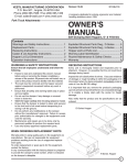
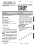
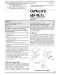
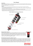
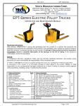
INSTRUCTION MANUAL
HEAVY-DUTY PIPE GRABS
MODEL PG (CAST IRON & STEEL)
FRONT VIEW
SIDE VIEW
MODEL NO. ________________________
SERIAL NO. ________________________
VESTIL MANUFACTURING CORP.
2999 NORTH WAYNE STREET, P.O. BOX 507, ANGOLA, IN 46703
TELEPHONE: (260) 665-7586 -OR- TOLL FREE (800) 348-0868
FAX: (260) 665-1339
URL: WWW.VESTILMFG.COM EMAIL: [email protected]
We produce several models of heavy duty pipe grab so that our customers may select a
product that satisfies specific requirements. The products identified on the front page
conform to the generalized performance specifications disclosed in this manual. Each
model fulfills our demanding standards for quality, safety and durability.
SAFETY PRINCIPLES
Vestil Manufacturing Corp. recognizes the critical importance of workplace safety. Each
person who might participate in the assembly, use, operation, or maintenance of the
product must read this manual. Read the entire manual and fully understand the
directions BEFORE assembling, using or maintaining the pipe grab. If you do not
understand an instruction, contact Vestil for clarification. Failure to adhere to the
directions in this manual may result in serious personal injury or even death.
Vestil is not liable for any injury or property damage that occurs as a consequence of
failing to apply the safe operation and maintenance procedures explained in this manual or
that appear on safety warning labels affixed to the product. Failure to exercise good
judgment and common sense may result in property damage, serious personal injury, or
death, and are not the responsibility of Vestil.
This manual applies the hazard identification methods suggested for instruction manuals
by the American National Standards Institute (ANSI) in ANSI standard Z535.6-2006. In
accordance with ANSI guidelines for hazard warning language, this manual identifies
personal injury risks and situations that could lead to property damage with SIGNAL
WORDS. These signal words announce an associated safety message. The reader must
understand that the signal word chosen to identify a particular safety hazard categorizes the
seriousness of that hazard according to the following convention:
These symbols
identify hazards
that may result in
personal injury
Identifies a hazardous situation which, if not
avoided, WILL result in DEATH or SERIOUS INJURY. Use of
this signal word is limited to the most extreme situations.
Identifies a hazardous situation which, if not
avoided, COULD result in DEATH or SERIOUS INJURY.
Indicates a hazardous situation which, if not
avoided, COULD result in MINOR or MODERATE injury.
Although Z535.6-2006 approves the use of “CAUTION” without an
accompanying safety alert symbol (black equilateral triangle with
yellow exclamation point) as an alternative to “NOTICE”, this
manual differentiates between hazards that pose a risk of
personal injury and those that create mere property damage
situations. CAUTION appears exclusively in conjunction with
the safety alert symbol to identify injury risks.
Identifies practices not related to personal injury,
such as operation that could damage the table. No safety alert
symbol (equilateral triangle enclosing an exclamation point)
accompanies this signal word.
-2-
TABLE OF CONTENTS
Safety Principles
Product Introduction
Safety Guidelines
Use Instructions
Maintenance & Inspections
Product Labeling
2
4
5
11-13
14-15
15
TABLE OF FIGURES
FIG. 1: Labeled Photograph
FIG. 2: Exploded Parts Diagram for PG-C/S-045 & PG-C/S-060
FIG. 3: Exploded Parts View for Models PG-C-100, PG-S-100
FIG. 4: Exploded Parts View for Models PG-C-140 and PG-S-140
FIG. 5: Exploded Parts View for Models PG-C-200 and PG-S-200
FIG. 3: Product Safety Label Placement
-3-
6
7
8
9
10
15
PRODUCT INTRODUCTION
Thank you for purchasing a Heavy Duty Pipe Grab (“pipe
grab” or simply “the grab”) made by Vestil Manufacturing
Corporation (“Vestil” or “Manufacturer”). Each pipe grab is a
durable, high-quality product that combines safety features and
superior lifting capabilities. Despite ease of use, all personnel
must familiarize themselves with the safe operation instructions
provided in this manual.
We produce 2 main types of heavy duty pipe grab, the PG-C and PG-S.
PG-C’s are constructed of cast iron; PG-S’s are made of steel. Additionally, we
offer several models of cast iron and steel grabs, which are distinguishable by
lifting capacity. Lifting capacity varies from 450lbs. to 2,000lbs. All models
incorporate 2 pipe guide weldments that engage the top of the pipe load. These
arms provide greater control of the load and the ability to easily release the load.
Vestil Manufacturing Corp. created this manual to acquaint owners and
users of our pipe grabs with safe use and maintenance procedures. Employers
are responsible for instructing employees to use the product properly.
Therefore, employees and any other persons, who might foreseeably use,
install or perform maintenance on the pipe grab, must read and understand
every instruction before using the pipe grab. Persons who use the pipe
grab should have access to the manual at all times, and in particular should
consult the directions before each use. Contact Vestil for answers to any
question you have after reading the manual.
Although Vestil strives to identify hazardous situations that could arise
during the use of its products, this manual cannot address every conceivable
danger. The end-user is responsible for exercising sound judgment at all times.
-4-
SAFETY GUIDELINES
Read the entire manual before attaching the pipe grab to a lifting device or using it for the first
time. Refer to the manual for safe use and maintenance procedures (p. 12-13). If questions
remain after you finish reading the manual, contact Vestil for answers. DO NOT attempt to resolve
any problems with the pipe grab unless you are certain that it will be safe to use afterwards, but
you must NEVER modify the product in any way without the express written approval of Vestil.
•
Electrocution Risk: DO NOT contact live electrical wires with the pipe grab or the load!
•
Consult the safety messages included in the manual for the crane, trolley, hoist, and any other device
used in conjunction with the pipe grab.
The pipe grab DOES NOT have a latch for holding the grab in an open or closed position. To open
the grab, lift one of both of the pipe guide weldments. DO NOT lift either arm while using the grab to
lift and/or move material.
ALWAYS inspect the coil hook before each use according inspection procedures described in ASME
B30.20. B30.20 also recommends frequent and periodic inspections. A brief synopsis of the
inspection recommendations appears p. 12 of this manual.
Properly maintain the pipe grab according to the maintenance procedures on p. 12-13. These
procedures were developed to supplement suggested maintenance practices of the ASME (B30.20).
The pipe grab must ALWAYS be attached to a safety hook (e.g. a chain or rope hoist that has a
safety hook attached to the end of the chain or rope) or to a connection that includes safety features
for preventing accidental/unintended detachment from the hoist. DO NOT use the pipe grab on a
hook that might release the grab. DO NOT connect the grab to a safety hook that does not function
properly or that is damaged.
DO NOT grab a load that has any debris or surface contamination on it. Remove debris, including
but not limited to oil, grease, dirt, or other material, that might affect the quality of the connection
between the grab and the load.
Clear all debris, including fluids, from the path of travel if the job requires moving the load to a new
location (as opposed to picking up the load and setting in down in the same position). Clear all such
debris BEFORE picking up the load! If moisture is present in the path of travel, absorb the liquid
before using the grab to reposition the load.
Make sure that no person is in the travel path of the load.
Verify the placement and legibility all safety warning labels as shown in FIG. 3 on p. 12. If any labels
become damaged or unreadable, contact Vestil for replacement(s). DO NOT use the hook UNLESS
all labels are attached and readable.
DO NOT attempt to lift an unbalanced load. Always use enough grabs to balance the load before
attempting to lift and/or move the load.
DO NOT sit on the load or apply any weight/pressure to a load grasped by the pipe grab.
DO NOT attempt to lift material that weighs more than the rated load of the grab. ALWAYS make
sure that the load weighs no more than the rated load of the pipe grab.
DO NOT lift a load higher than necessary. (See “Use Instructions” on p. 8-10).
DO NOT raise the load over your feet or any other part of your body. DO NOT use the pipe grab to
lift material over people!
DO NOT use the pipe grab to lift any apparatus that is used to support people, such as a platform or
scaffold.
Always orient yourself so that the load is visible to you. You are less likely to be injured by the load if
it remains within sight at all times. Standing to one side of the load next to the pipe grab will allow
you to stabilize the load as you move it to the desired location. You should hold onto the hoist
(safety) hook with one hand and to the load with the other hand if the lifting device is manually
operated, or to the hoist hook with one hand if the lifting device is electronic/motor-driven.
DO NOT leave a suspended load unattended. Always use the pipe grab to move a load to its desired
location, then set the load down and properly immobilize it; then disengage the grab from the load
BEFORE leaving the work area. An unattended, suspended load creates a risk of injury to yourself
and others.
•
•
•
•
•
•
•
•
•
•
•
•
•
•
•
•
-5-
FIG. 1: Labeled PG-C (& PG-S) photographs
Upper
frame
pin
Formed
Hook
Bracket
Pipe Guide
Weldment
Lower
frame
pin
Load-engaging
portion of pipe
guide weldment
Lever
Arm
Frame
-6-
FIG. 2: Exploded Parts View for Models PG-C-045, PG-C-060,
PG-S-045, PG-C-060
Item No.
1
Part No.
2
3
4
5
28-014-196
28-014-199
28-014-197
28-016-090
25-516-043
28-014-198
6
26351
7
8
9
10
11
12
13
14
37024
33008
28-112-024
28-112-025
11109
33012
33434
68017
Description
Quantity
Lever Arm (Frame)
3
Top Link (Frame)
Formed Hook Bracket
Pipe Guide Weldment
Link Arm (Frame)
Socket Head Shoulder Bolt,1/2 x 1-1/4
with ¼ Hex, 3/8-16UNC Threads
3/8 Nylock Insert Nut
3/8 USS Flat Washer Z Plated
Lower Frame Pin
Upper Frame Pin
3/8-16x1-1/2 Z Plated
½ Z-plated Flat Washer
7/8 x 18Ga. Machine Bushing
External Snap Ring, 7/8 Shaft
3
1
2
4
-7-
2
8
6
1
1
6
2
2
2
FIG. 3: Exploded Parts View for Models PG-C-100, PG-S-100
Item No.
1
2
3
4
5
6
7
Part No.
28-514-168
28-014-199
28-014-200
28-016-090
28-516-044
28-014-201
26351
8
9
10
11
12
13
14
15
11109
37024
33008
28-112-024
28-112-025
33012
33434
68017
Description
Lever Arm Weldment with Stop Block
Lever Arm (Frame)
Top Link (Frame)
Formed Hook Bracket
Outrigger Arm Weldment
Link Arm (Frame)
Socket Head Shoulder Bolt, 1/2x1-1/4
with ¼ Hex, 3/8-16 UNC Threads
3/8-16x1-1/2 Z-plated Bolt
3/8 Nylock Insert Lock Nut
3/8 USS Z-plated Flat Washer
Lower Frame Pin
Upper Frame Pin
½ Z-plated USS Flat Washer
7/8I.D.x18GA. Machine Bushing
External Snap Ring,7/8 Shaft
-8-
Quantity
1
2
3
1
2
4
2
6
8
2
1
1
2
2
2
FIG. 4: Exploded Parts View for Models PG-C-140 and PG-S-140
Item No.
1
2
3
4
5
6
7
8
9
10
11
12
13
14
15
Part No.
28-514-168
28-014-199
28-014-200
28-016-090
28-516-044
28-014-201
26351
11109
37024
33008
28-112-024
28-112-025
33012
33434
68017
Description
Lever Arm Weldment with Stop Block
Lever Arm (Frame)
Top Link (Frame)
Formed Hook Bracket
Outrigger Arm Weldment
Link Arm (Frame)
Socket Head Shoulder Bolt, ½ x 1-1/4 with ¼
Hex. 3/8 – 16 UNC Threads
3/8 – 16 x 1-1/2 Z-plated HHCS #2
3/8 Nylock Insert Nut
3/8 Z-plated USS Flat Washer
Lower Frame Pin
Upper Frame Pin
½ Z-plated USS Flat Washer
7/8 I.D. x18GA.
External Shaft Ring, 7/8 shaft
-9-
Quantity
2
3
1
2
4
2
6
8
2
1
1
2
2
2
FIG. 5: Exploded Parts View for Models PG-C-200 and PG-S-200
Item No.
1
2
3
4
5
6
7
8
9
10
Part No.
28-014-205
28-112-022
28-016-096
28-014-206
28-112-023
28-016-097
28-514-045
28-516-046
33016
26372
11
12
13
33012
37030
26351
14
37024
Description
Lever Arm (Frame)
Lower Frame Pin
Arm Link Bracket
Top Link (Frame)
Upper Frame Pin
Formed Hook Bracket
Pipe Guide Weldment
Outrigger Link Weldment
5/8 USS Flat Washer Z-plated
Socket Head Shoulder Bolt, 5/8x1-3/4
with 5/16 Hex, ½ -13 UNC Threads
½ Z-plated USS Flat Washer
½-13 Nylock Insert Lock Nut
Socket Head Shoulder Bolt 1/2x1-1/4
with ¼ Hex, 3/8-16 UNC Threads
3/8 Nylon Insert Lock Nut
- 10 -
Quantity
3
1
4
3
1
1
2
2
4
2
2
2
6
6
Use Instructions:
The operating instructions in this manual are meant to supplement the operating
recommendations of the ASME that appear in B30.20.
Only trained, designated persons should use the Pipe grab. “Designated person” means someone
selected by his or her employer, or by a representative of the employer, as competent to use the pipe
grab. Trainees under the direct supervision of a designated person may use the device. Maintenance
and personnel who perform tests also may use the pipe grab when necessary for the performance of their
employment duties.
Step 1: Connect the Pipe Grab to the hoisting device that will be used. The pipe grab should be
connected to the hoist with a safety hook to prevent accidental detachment from the hoist.
Safety Hook
Properly functioning safety latch
Step 2: Test the pipe grab for normal function. Lift each of the stabilizing/releasing arms to verify that the
grab opens and closes smoothly.
2
1
Step 3: Move the pipe grab into position above the load.
Step 4: Grasp the object. Lift one of the pipe guide weldments to open the grab (photo 5), and while
open, lower the grab around the object (photo 6). Lower the pipe guide weldment until the load-engaging
portions of both arms (identified in FIG. 1) contact the top of the load material (circled in photo 7).
5
6
- 11 -
7
Step 5: Make sure that the load is balanced. Lift the load just a few inches off of the ground or supporting
surface to see if it remains horizontal. If the load dips on one side of the grab, lower the load until it fully
rests on the ground/supporting surface and immobilize it. Release the load by lifting up on one of the
pipe guide weldments. Move the grab slightly towards the end of the load that hung lower when lifted.
Raise the object again just a few inches into the air to check the balance of the load.
Once the load is properly balanced, proceed to step 6. “Proper balance” means that the load is level
(both ends of the load stay at the same height) when raised.
Step 6: Raise the load and move it to the desired location. Once proper balance is established, grasp the
hoist hook as shown in photo 8, and raise the load to waist height. If the object has to be removed from a
container or lifted over an obstacle, raise the load ONLY as high as necessary.
We recommend elevating the load to approximately waist height.
Review all hazard safety messages (p.5) and always follow these rules when using the pipe
grab:
• NEVER lift material over yourself or other persons. Inform persons in the area that you will be using the
grab and make sure that no one is in the starting point, path of travel, and end point.
• DO NOT press down on the object. Grasp the hoist hook to stabilize the load while elevated and/or
traveling to a new location.
If you are using a motorized trolley to reposition the object, DO NOT pull on the hoist hook. Allow the trolley to
do all of the movement. Your hold on the hoist hook is a means ONLY for stabilizing the load.
• Always stand at arm’s length to the side of the load and hold onto the hoist hook as shown in photos 8-10.
Make sure that your clothing, feet, and all other body parts stay clear of the load. This stance allows the
operator to exercise some control of the load while maximizing safety.
If you are using an unmotorized trolley,
• Grasp the hoist hook with one hand. Contact the top of the load with your other hand, but DO NOT press
down. Use the second hand only to steer the load. DO NOT pull the object in the direction of travel. Use
the hand that grasps the hoist hook to move the trolley in the intended direction of travel.
8
9
- 12 -
10
Step 7: Lower the load to the ground/supporting surface (photos 11 and 12). Position the object above
the surface that will receive it (ground, pallet, work platform, etc.). Make sure that the load is motionless
before beginning to lower it.
11
12
Step 8: Once the load has been fully lowered, immobilize it. Disengage the pipe grab by lifting one or both of
the pipe guide weldments. Raise the grab so that it is completely free of the load.
13
14
15
16
- 13 -
Maintenance and Inspections:
A designated person must verify that the device complies with all regulations, codes, and standards that
apply to “Under-the-Hook Lifting Devices” in the location where the pipe grab is used. The person
designated to conduct inspections must do so before the pipe grab is used for the first time, and EACH
time the grab is installed for use.
Inspections:
The end-user is responsible for performing inspections as recommended in ASME B30.20,
which categorizes examinations based on regularity of performance. Highlights of the recommended
inspection procedures appear below. The reader must recognize that Vestil has merely reproduced an
outline of the ASME recommendations, and the full explanations as given in the published standard must
be used.
DO NOT use a pipe grab that bears structural damage, such as bent jaws, deformation
of the clevis or support pin(s), damaged pipe guide weldments. Restore the grab to normal operating
condition BEFORE using the grab again.
Inspections Before & During EVERY lift: visual examination must be performed by the operator prior to
AND during each lift. In particular, the operator should inspect for:
1. Debris on the load surfaces; AND
2. Condition and operation of the controls.
Frequent Inspections: the specific meaning of “frequent” varies from daily to monthly depending on the
service classification (normal, heavy, severe, and special/infrequent) of the pipe grab. Definitions of the
service classifications appear in ASME B30.20. The operator or other designated person(s) should
visually inspect the pipe grab for:
1. Deformation, cracking, or excessive wear of any part of the pipe grab;
2. Operating mechanisms for conditions that interfere with proper function; AND/OR
3. Loose or missing fasteners, stops or nameplates.
Periodic Inspections: complete visual inspections performed AND recorded by a qualified person. The
inspection should specifically look for:
1. Loose bolts or fasteners;
2. Excessive wear of friction pads, linkages, and other mechanical parts; AND/OR
3. Excessive wear at the points where the grab connects to the hoist hook, and load support
clevises or pins.
Maintenance: the end-user must implement a maintenance program to ensure the proper function and
safety of the pipe grab. A qualified person may establish a program that is used in preference to the
maintenance procedures described below. However, if you apply the procedure below, complete EVERY
step each time maintenance is performed.
ONLY qualified persons may perform maintenance on the pipe grab.
Step 1: All sources of power must be disconnected, locked out and tagged, “Out of Service.”
Step 2: Disconnect the pipe grab from the hoist hook, and tag it as, “Out of Service.”
Step 3: Perform all adjustments identified as necessary during any inspection (every lift, frequent, or
periodic). Consult ASME B30.20, paragraph 20-1.3.1 through 20-1.3.5, for recommended inspection
procedures.
Step 4: If other conditions exist which require new/replacement parts to repair, contact Vestil to order
replacement parts. Deformity, corrosion, rusting, or excessive wear of fasteners, jaws, pipe guide
weldments, or the clevis warrants immediate replacement of the affected part(s).
The reader should understand the significant difference between “Adjustments [and]
repairs,” and modifications. An adjustment or repair refers to a simple correction that restores the grab to
normal operating condition, such as tightening loose fasteners, or removing debris from the surface of the
grab. A modification is a change that alters the grab from normal operating condition, like bending the
- 14 -
(Continued from previous page)
structural members or removing the pipe guide weldments. NEVER modify the pipe grab without the
express, written approval of Vestil. Modifications may render the pipe grab unsafe to use.
DO NOT use the pipe grab if adjustments and/or repairs are incomplete! Return the grab to service
ONLY after finishing all necessary repairs and/or adjustments.
Step 5: Perform a periodic inspection, as recommended in ASME B30.20.
Step 6: Make a dated record of the repairs, adjustments and/or replacements made.
Product Labeling:
Only use the pipe grab if ALL of the labels are readable and undamaged. Contact Vestil for replacement
labels.
FIG. 3: Product safety label placement
“Made in
USA”
label
Manufacturer’s
Name label
“Made in
USA”
label
Maximum
Capacity
label
- 15 -