1
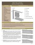
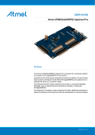
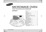
TREX SECLUSIONS DOUBLE GATE INSTALLATION GUIDE TREX SECLUSIONS DOUBLE GATE INSTALLATION GUIDE ® ® TOOLS NEEDED OPTIONAL ANTI-SAG CABLE KIT For large gate panels, it may be neccssary to use an anti-sag cable to eliminate the sag of a gate panel. Anti-sag cable kits can be purchased through your local Trex Distributor. SECLUSIONS DOUBLE GATE COMPONENTS A Seclusions 5x5 fence post B Seclusions fence gate panels (2) B1 Active panel B2 B1 B2 Non-active panel C Steel post stiffener (2) ANTI-SAG CABLE KIT COMPONENTS D Seclusions fence hinge (4) A Black vinyl wrapped steel cable E Seclusions fence latch B B Cable clamp (2) F Seclusions striker C ‘S’ hook A G Seclusions gate handle (2) D ‘D’ rings (2) F E 1” Self-drilling screws (2) H Seclusions drop rod assembly I C F Turnbuckle J 2” self-drilling screws (6) H 1-1/2” self-drilling screws (40) K 1” self-drilling screws (16) D BACK SIDE OF B2 E BEFORE YOU BEGIN » Read all instructions before installation. » Follow Trex Seclusions Installation Instructions to lay out fence and dig holes. STEP 1: SET THE GATE POSTS ATTACHING THE CABLE KIT Note: To make installation easier, prop the gate to the desired level using a block of wood under the latch side edge of the gate panel. Note: Due to concrete cure times, set the gate posts 2-3 days before gate is installed. A. Attach upper ‘D’ ring to the “hinge side” of the panel, 5-1/2” down from top of gate and 1-3/4” from the edge of gate (to hit the inner steel frame), using (1) self-drilling screw. A. Slide a Steel Post Stiffener into each hinge post. Open side of insert should face away from gate opening. B. Attach lower ‘D’ ring to the “latch side” of the panel, 2” up from bottom of gate and 1-3/4” from the edge of gate, using (1) self-drilling screw. B. Set posts into post holes that are 30” deep (or to frost line) by 12” wide. C. Lengthen the turnbuckle as long as possible before proceeding by twisting the center ring. Attach the turnbuckle to the upper “D” ring using the “S” hook. C. Opening (measuring from inside edge of post to inside edge of post) for Trex Double Gate using (2) large gate panels should be 130-1/2”. Inside faces should be plumb and parallel. D. Loop one end of the cable through the lower eye bolt of the turnbuckle. Attach a cable clamp and tighten nuts as tight as possible. Opening for double gate using two small panels should be 91-1/2”. For custom size double gates the opening is 2-3/4” larger than the combined panel widths. E. Loop the other end of the cable through the lower “D” ring and attach the other cable clamp. Pull the cable as tight as possible before tightening the nuts. F. A. Remove any slack by tightening the turnbuckle, twisting the center ring of the turnbuckle. HINGE SIDE LATCH SIDE Note: If Hinge Post is not connected to a fence panel, it may be necessary to use a Heavy Steel Post Stiffener or to fill the post with concrete for additional strength. Check for level. C. 130-1/2” 30” B. 12” ©2013 TFSC TREX SECLUSIONS DOUBLE GATE INSTALLATION GUIDE TREX SECLUSIONS DOUBLE GATE INSTALLATION GUIDE ® ® TOOLS NEEDED STEP 2: INSTALL THE GATE PANEL A. Attach the hinges to the gate panel approximately 6” from SECLUSIONS DOUBLE GATE COMPONENTS STEP 4: MOUNT THE DROP ROD TO THE NON-ACTIVE PANEL A. 6” the top and bottom of the gate using a 3/8” nut driver and the (4) 1-1/2” supplied self-drilling screws. Pre-drilling with a 3/16” drill bit will make installation easier. A. A. Attach the drop rod brackets to the back side of the non-active gate panel. Reverse the drop rod brackets depending on which side of the gate the drop rod is to be mounted. Note: Install hinges on the side of the gate that you want the gate to swing toward. B. Place the gate panel in the opening. Adjust the gate to be level and to the desired height by placing blocks under gate panel. Allow ample clearance for full swing of gate. Swing direction Swing direction C. Using (4) 1-1/2” supplied self-drilling screws, attach each hinge to the steel inserted gate post. Pre-drilling with a 3/16” drill bit will ease installation. 6” C. E. Repeat the process to hang the other gate panel. create an even 7/8” gap between the panels and so the tops of the panels are even. x2 D. B. D. Mark the location on the ground where the drop hits. If your gate is over a concrete pad, drill an 8” deep hole using a 3/4” masonry bit for the drop rod to slide into when the gate is closed. For gates over dirt, dig a hole 8” wide x 18” deep below the drop rod, fill it with concrete, and insert an 8” long 3/4” pvc pipe in the concrete for the drop rod to slide into after the concrete has cured. STEP 3: ATTACH THE LATCH AND HANDLES from the ground using (6) 1-1/2” supplied self-drilling screws. The catch is to be placed in the direction of the gate swing. The catch may face up or down depending on the direction of gate swing. B. Using the (4) 1-1/2” supplied self-drilling screws, attach the striker to the active gate panel, lining the striker rod up with the catch on the post latch. A. 24” 14” B. Gate swing 3” Catch Catch STEP 5: MAKE ANY FINAL ADJUSTMENTS TO THE GATE HINGES AS NEEDED B. A. To adjust a sagging gate, or to shift panel in the opening, loosen the hinge nuts with an 11/16” wrench. Gate swing x4 C. Attach gate handles to the active gate panel, using (2) 1” B. Loosen or tighten the nuts in the direction shown below. Lift or push panel to slide the hinge. C. Retighten the hinge nuts. supplied self-drilling screws. Handles should be attached 1-3/4” from the edge of the gate panel. The height must be staggered front and back as shown. 1-3/4” Shift panel left C. ©2013 TFSC C. x4 F. Adjust hinges using the method described in Step 5 to A. Attach the latch to the non-active panel approximately 36” 2” C. Attach the drop rod hanger 24” from the bottom of the gate panel and 2” to the center of the screw holes from the edge of the gate panel. D. Open the panel and attach the inside corner of the bracket to the gate post. B. Measuring from the horizontal tab (see below), attach the lower bracket 3” from the bottom of the gate panel using (3) 2” self-drilling screws on the inside edge of the gate panel and (1) 1” self-drilling screw on the face of the gate panel. Repeat this process for the upper bracket, attaching it 14” from the bottom of the panel. Shift panel right Raise latch side Lower latch side Top Hinge Top Hinge Top Hinge Top Hinge Bottom Hinge Bottom Hinge Bottom Hinge Bottom Hinge D. Due to weather and temperature changes, periodic hinge adjustment may be necessary to assure proper latch connection.