1
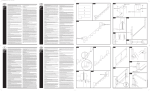
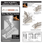
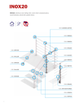
Veranda Railing System
Veranda railing systems are designed to work with a number of different
decking materials and surfaces. Before initiating any project, obtain a copy
of your local building codes and understand them thoroughly. Local building
code requirements will always supersede any and all suggested procedures and
measurements in the following installation guideline.
Post sleeve over wood post
Use the Post Sleeve method to install railing directly to a wooden 4x4 deck post.
This is ideal for new deck construction methods that attach the rim joist directly to
the 4x4 deck support posts, where wood 4x4 deck support posts extend through
the deck serving as rail posts, or in those code compliant applications where the
use of existing 4x4 wooden rail posts is desired.
1. Ensure 4x4 wooden posts are code compliant and, where possible, spaced
equally for the best looking applications. Wood 4x4 dimensions should be
3.5”x3.5”.
2. Determine the desired height of post sleeve. Typically, the height is no less
than 2” above top of the finished railing system. This ensures the proper
placement of post caps that slide down over the top of the post sleeve.
3. Cut the post sleeve to the desired height.
4. The wood post should be approximately 1” shorter than the height of the
post sleeve. Cut wood post as necessary.
5. After decking is installed, slide post sleeve over the wood 4x4 (Fig. 1).
RAILING INSTALLATION
The following instructions describe the installation of three types of railing
sections: Line, Stair, and Angled
Note: Once posts and/or post sleeves are installed, ensure they are plumb and level. Prior
to fastening any sections to the posts, install Base Cove Moulding for a finished look (Fig.
1). Base Cove Moulding may not be installed after sections are attached to posts.
Figure 1
Figure 2
Top Rail Bracket
Line Rail Installation
1. Measure the inside distance between properly installed, plumb posts.
2. Mark the rails for the inside distance between the posts. The distance from
the end of the rail to the first baluster hole should be equal on both ends of
the rail. Ensure that all screws will fasten into the rail and none fall into the
routed baluster holes (Fig. 2,3).
Figure 3
Note: Minimum distance from post to first baluster hole 1 9/16”.
3. Cut the top and bottom rail to fit tightly between the posts. The bottom rail
is identified by the white “BOTTOM” sticker inside the profile.
4. Center the “L” bracket on the underside of the bottom rail (Fig. 2). Inset the
“L” bracket 1/16” from the end of the rail. Mark the three hole locations on
the rail. Predrill 1/8” hole at desired locations. Repeat for opposite end.
5. Secure the “L” bracket to the bottom rail using three #10 x 3/4” long screws.
Repeat for opposite end. DO NOT OVERTIGHTEN SCREWS.
6. Center the “L” wing bracket on the underside of the top rail (Fig. 3). Inset the
“L” wing bracket 1/16” from the end of the rail. Mark the three hole locations
on the rail. Pre-drill 1/8” hole at desired locations. Repeat for opposite end.
8. Secure the “L” wing bracket to the top rail using three # 10 x 3/4” long
screws. Repeat for opposite end. DO NOT OVERTIGHTEN SCREWS.
9. Ensure that the base cove moulding is in place at the bottom of the posts (Fig.
5).
10. Cut a crush block from an extra baluster to your desired length (min. 3”
required length/height). Place the crush block on the deck surface midway
between the posts (Fig. 5)
11. Place the bottom rail on the crush block between the posts. The baluster
holes should be facing upward (Fig. 4). Level the bottom rail and center the
rail ends on each post.
12. Mark the two “L” bracket hole locations on post. Pre-drill 1/8” holes at the
desired locations. Repeat for opposite end.
13. Secure the bottom rail to the post using two #10 x 2” long screws. Repeat for
opposite end. DO NOT OVERTIGHTEN SCREWS.
Figure 4
Top
Bracket
(Step 17)
Note: A flexible shaft bit holder (not included) is helpful during this step.
14. Fully insert a baluster into each pre-routed hole in the bottom rail.
15. Position the top rail onto balusters and between the posts. The pre-routed
holes in the top rail should be facing downward (Fig. 4).
16. Individually insert each baluster into the corresponding pre-routed hole in the
top rail. Maintain the engagement of the baluster in the bottom rail.
17. Once all balusters are inserted in the top rail, gently push downward on top
rail to ensure full engagement of balusters in top and bottom rail. (Fig. 5).
18. Center the ends of the top rail on the post. Mark the two “L” wing bracket
hole locations on each post. Slightly pull the section toward the deck. Pre-drill
1/8” holes at the desired locations.
19. Reposition top rail between posts. Secure the top rail to the post using two
#12 x 2” long screws. Repeat for the opposite end. DO NOT OVERTIGHTEN
SCREWS.
Figure 5
Note: A flexible shaft bit holder (not included) is helpful during this step.
20. Using PVC cement, glue crush block to underside of bottom rail midway
between the posts.
21. Mount and glue post caps on posts after all rail sections are installed.
Stair Rail Installation
Note: The stair systems are designed for the typical angles created by an approximate
7” rise/11” run with allowance for accepted variation in components. Building codes are
very specific on allowable angles and widths. It is very important to consult with your
local building code officials and plan your stair layout accordingly. Ensure that you leave
adequate space for graspable hand rail if applicable. “Dry fitting” intermediate post
placement will result in easier and better looking installations and may avoid placement of
post mounting brackets in areas where screws cannot attach to the guardrail.
1. 2. Figure 6
Position two line posts at top of stairway with the desired spacing and secure
each post with the appropriate bracket (Fig. 6).
Install the outside stair stringers just wider than the posts’ location. The posts
mounted at the bottom of the stairs will be on the inside of the stringer and
will line up directly with the posts at the top of the stairs.
3. Install each post at the bottom of each stair, using a wooden 4” x 4” or Surface
Post Sleeve Mount.
Note: For stairs longer than six feet, it will be necessary to use multiple stair sections. The
distance between posts, measured at an angle should not exceed 70 inches. Ensure all posts
are plumb prior to final mounting.
Note: When installing the bottom post sleeves inside the stringers, additional support may
be required for stair treads that butt into the post.
4. Identify the bottom rail by locating the white “BOTTOM” sticker inside the
profile.
5. Lay bottom rail on stair with marked end (Fig. 8) at lower post. Center the rail
between the posts so that the distance from the post to the first baluster hole
is equal on both ends (Fig. 7).
Figure 7
Note: Minimum distance from post to first stair baluster hole is 2 1/4”.
6. Mark angles on rail.
7. Cut the bottom rail to length. Ensure that the rail fits tightly between the
posts.
8. Using bottom rail as a guide, line up top rail baluster holes with bottom rail
baluster holes and with the “marked” ends together (Fig. 8). Mark the cut
lines on the top rail.
9. Cut top rail to length.
10. Center the hinged bracket on the underside of the bottom rail (refer to Fig.
2). Inset the hinged bracket 1/16” from the end of the rail. Mark the three
hole locations on the rail. Predrill 1/8” hole at desired locations. Repeat for
opposite end.
Figure 8
11. Secure the hinged bracket to the bottom rail using three #12 x 3/4” long
screws. Repeat for opposite end. DO NOT OVERTIGHTEN SCREWS.
12. Center the hinged bracket on the underside of the top rail (refer to Fig.
3). Inset the hinged bracket 1/16” from the end of the rail. Mark the three
hole locations on the rail. Pre-drill 1/8” hole at desired locations. Repeat for
opposite end. Secure the Hinged bracket to the top rail using three #12 x 3/4”
long screws. Repeat for opposite end. DO NOT OVERTIGHTEN SCREWS.
13. Lay the bottom rail with baluster holes upward, onto a 1/4” wood spacer
located between the posts (Fig. 9). This provides the rail spacing between the
rail and stair treads and helps to stabilize the setup.
14. Using the hinged bracket as a template, swing the unsecured leg of the
bracket downward so it touches the post. Mark the two hole locations at each
end of rail on post.
15. Remove the bottom rail and pre-drill marked holes using a 1/8” drill bit.
16. Ensure that the base cove moulding is in place at the base of the posts (Fig.
9).
17. Replace the bottom rail on the 1/4 inch wood spacer located between posts.
18. Fully secure bottom rail to post using two #12 x 2” long screws. Repeat at
opposite end. DO NOT OVERTIGHTEN SCREWS.
19. Fully insert ends of balusters into pre-routed holes on bottom rail.
20. Place top rail onto top end of balusters and between posts. Individually insert
top end of each baluster into pre-routed holes of top rail (maintain baluster’s
engagement in bottom rail).
21. Once all balusters are inserted in the top rail, gently push downward on the
top rail to ensure full engagement of balusters in top and bottom rail.
22. Center the top rail on each post and swing unsecured leg of hinged bracket
downward so it touches the post.
23. Using the hinged bracket as a template, mark the two hole locations on each
post.
24. Slightly pull assembled section toward staircase to gain access to holes.
Predrill 1/8” holes at desired locations in each post.
25. Re-center the top rail on post. Secure top rail to post with two #12 x 2” long
screws. Repeat for opposite end. DO NOT OVERTIGHTEN SCREWS.
26. Remove wooden spacer between bottom rail and stair treads.
27. Mount and glue post caps using PVC cement after all rail sections are
installed.
Angle Rail Installation (Available by Special Order)
Rails up to 30 degrees may be mounted to the post face by using the In Line “L”
Bracket. Rails should be cut at the appropriate angle to fit tight against post.
Cutting rails greater than 30 degrees will result in a rail that does not fully fit on
post. Angles greater than 30 degrees require the use of the Angle Mount Bracket
(Sold Separately).
Figure 9
Figure 10
1. Determine the angle of your installation by using the supplied template
(located on the back page of this booklet).
2. Cut the template out along the appropriate marked lines. (You may want to
photocopy the template as a backup prior to cutting).
3. Identify the bottom rail by locating the white “BOTTOM” sticker inside the
profile.
4. Position the template on the non-routed flat side of the top rail. Mark the
proper cutting angle (Fig. 10).
5. Flip the template over and place the template on the non-routed flat side of
the bottom rail (Fig. 10). Mark the proper cutting angle.
6. Prior to cutting, ensure baluster holes are equidistant from the end of rail to
ensure proper vertical alignment.
Angle
Mount
Bracket
Note: Minimum distance from post to first baluster hole 1 9/16”.
7. Make angle cuts in top and bottom rails.
8. Align the angled brackets with the 90 degree cut in the railing. Inset the
bracket 1/16” from rails end. Mark the three screw hole locations on both
rails. Repeat at opposite end.
9. After fitting angles to posts, follow the Line Rail instructions (Steps 5 through
20) to complete the rail section installation.
VER-0020-LIT 2/10
Figure 11