1
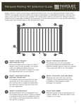
®
I n s t r uc t ion Manual
®
Preparation & Tool Checklist
BEFORE YOU BEGIN:
IMPORTANT PRODUCT SAFETY AND PRE-INSTALLATION INFORMATION
Failure to follow these instructions may lead to an unsafely INSTALLED product and will adversely affect
coverage under the Limited Warranty. The following installation instructions are provided to guide you through the installation
process of the Marquee™ Railing System. TAMKO® Building Products, Inc. shall not be held liable for improper or unsafe installations. TAMKO
recommends that all designs be reviewed by a licensed architect, engineer or local building official before installation to ensure that they are safe
and in compliance with local building code requirements.
Fire and other sources of excessive heat may damage Marquee Railing. Damage caused by fire or other heat sources may include melting,
sagging, warping, discoloration, charring, increased expansion or contraction, accelerated weathering, etc.
Low-E glass is one potential source of excessive heat because it is designed to reflect more sunlight than traditional glass. This enhanced
reflectivity combined with any irregularity in the window glass can concentrate sunlight onto the railing and cause heat build-up on areas of the
railing surface. When this occurs, damage of Marquee Railing is possible. Contact the manufacturer of the product which contains the Low-E
glass for suggestions to reduce or eliminate the reflected heat.
A railing system which has been damaged or exhibits signs of excessive wear or weakness must be replaced or repaired immediately as it may be a safety hazard.
Composite railing will retain heat when exposed to direct or reflected sunlight. Exercise caution around these heated surfaces.
COMPONENTS NEEDED TO INSTALL ONE MARQUEE RAIL SECTION:
Kit Selection Guide:
Customizing the look of a Marquee Railing System is simple.
Just select at least one of each component kit* listed below
to add style and distinction.
A
straight/stair rails
6-Foot or 8-Foot Straight Rail Kit
6-Foot Stair Rail Kit
• Contents: (2) Pre-routed Rails and (1) Crush Block (no crush block in Stair Rail Kit)
B
post kits
5" x 5" x (48" or 120") Post Sleeve
• Contents: (1) Post Sleeve and Wood Post Spacer
5" x 5" x (38" or 44") Wood Post Mount Kit
5" x 5" x (38" or 44") Concrete Post Mount Kit
• Contents: See page 7-10 for full details.
C
brackets
Straight Bracket Kit
Stair Bracket Kit
• Contents: (4) Brackets and (1) Rail Screw Pack
Multi-Angle (Left) Bracket Kit
Multi-Angle (Right) Bracket Kit
• Contents: (2) Brackets and (1) Multi-Angle
Screw Pack
D
E
balusters
36-Inch or 42-Inch Baluster Kits (6-Foot section)
• Contents: (13) Square Balusters
36-Inch or 42-Inch Baluster Kits (8-Foot section)
• Contents: (18) Square Balusters
post caps and rings
5" x 5" Post Cap
5" x 5" Post Ring
*Note: each component kit is sold separately. Kit types and quantities vary by application.
SUBSTITUTION FOR THESE COMPONENTS IS NOT ALLOWED AS SUBSTITUTING COMPONENTS COULD CAUSE A SAFETY HAZARD.
MEASURE SPAN BETWEEN POSTS:
Marquee Rail Kits are designed for 6' or 8' lengths from center-to-center of posts. TAMKO recommends verifying the span between posts before
beginning installation.
TOOLS REQUIRED FOR INSTALLATION:
Safety glasses, hearing protection, tape measure, miter saw or hack saw, drill, #2 square drive bit and level. For larger construction projects, a
miter saw and drill are strongly recommended for quicker installation.
TABLE OF CONTENTS:
Preparation & Tool Checklist. . . . . . . . . . . . . . . . . . . . 1
Straight Rail Install Instructions . . . . . . . . . . . . . . . 2
Horizontally angled rail install Instructions . . . 4
Stair Rail Install Instructions. . . . . . . . . . . . . . . . . . . 5
Post Mount Installation Wood/Composite . . . . . . . . 7
Post Mount Installation Concrete. . . . . . . . . . . . . . . 8
STRAIGHT RAIL INSTALLATION
FIGURE 1
Fig. 1
INSTALLATION STEPS:
1 Install and prepare posts or other mounting surfaces for Marquee™ Railing installation.
Ensure mounting surfaces are level and plumb. (Fig. 1) TAMKO® recommends using
Marquee Post Mount systems or wood posts covered with our matching Marquee
Post Sleeve and Marquee Wood Post Spacers.
To install Marquee Post Sleeve with a nominal 4" x 4" wood post:
1Slide the first Marquee Wood Post Spacer over the 4" x 4" wood
post and secure in place flush with the deck surface using the
screw provided.
2 Next, slide the second Marquee Wood Post Spacer over the 4" x 4"
wood post and secure in place with the bottom of the Wood FIGURE
Post2
Spacer 29-1/2" above the deck surface for a 36" rail height, or
35-1/2" for a 42" rail height.
3 Finally, place the Marquee Post Ring on the bottom of the Marquee
Post Sleeve and slide post sleeve over the wood post.
Fig. 2
IMPORTANT: Use of the Marquee Wood Post Spacer is required for 4" x 4" wood
post applications. Failure to follow these instructions may lead to an unsafely
installed product and will adversely affect coverage under the Limited Warranty.
To install the Marquee Post Mount Kit, see the full post mount instructions on
pages 7-10.
2 Measure the length between posts and confirm which Marquee Railing Kit is
required (Fig. 2)
Fig. 3a
FIGURE 3
Marquee Railing Kit Lengths:
Nominal Rail Length
6'
8'
Actual Rail Length
67"
91"
3 Lay the bottom rail beside the post sleeves with the pre-routed baluster holes facing
upward and evenly spaced. The rails should extend past the post sleeves on each
side. Mark both ends of the rail where they cross the post sleeve. (Fig. 3a)
IMPORTANT: A minimum of 1-5/8" rail length is required from the end of rail
to first baluster on both ends of the rail. (Fig. 3a) Check end spacing and shift
the position of the rail before cutting if required. Ensure that the gap between
posts and balusters will not exceed 4".
MINIMUM 1-5/8"
FIGURE 4
Fig. 3b
When positioned and marked properly cut the bottom rail.
4 Lay the top rail beside the bottom rail with the pre-routed baluster holes aligned.
Mark and cut the top rail to match the bottom rail length and end spacing. (Fig. 3b)
5 To install the bottom rail brackets, place the bottom of the bracket on the top edge
of the Marquee Post Ring and center on post. Secure in place using two of the
screws provided in the Marquee Straight Bracket Kit. Use 2" screws when mounting
to a wood post or the 1-1/4" screws when mounting to Marquee Post Mount.
Repeat on post at opposite end of rail section. (Fig. 4)
1-5/8" MINIMUM DISTANCE
FROM FIRST BALUSTER HOLE
TO END OF RAIL
2
STRAIGHT RAIL INSTALLATION
(Continued)
FIGURE 5
Fig. 4
6 Attach the crush block included with the Marquee Rail Kit on the underside of the
bottom rail using the screw provided with the crush block. Center the mounting plate
on the deck surface so that it will be in line with the crush block installed on the bottom
rail. Screw the mounting plate to the deck using the supplied screw.
7 Insert bottom rail into the bottom rail brackets, making sure the rail is level. Secure
the bottom rail in place by installing two self-drilling 1" screws provided in the
Marquee Straight Bracket Kit on each side of the brackets. (Fig. 5)
8 Pull down on the bottom portion of the crush block until it sits flush with the deck
surface. Secure in position by installing the supplied retaining screw and colormatched snap cap into the side of the crush block.
FIGURE 6
NOTE: Be sure to check with your local building code officials for any bottom
rail clearance or rail height requirements. Improper rail clearance or rail height
could cause a safety hazard.
Fig. 5
9 Insert balusters into pre-routed holes on the bottom rail, making sure each one is
fully nested.
10 Align the top rail over the balusters and install one at a time into the pre-routed
holes. Ensure the top rail is fully nested and level with the bottom rail. Position
the top rail brackets on the rail, center the bracket on the post and mark the
bracket locations on each post. (Fig. 6)
11 Remove the brackets from rail. Tilt the rail outward from the post slightly to expose
the face of the post. Reposition the top rail brackets at the marked locations on
FIGURE 7
each post and install with screws provided in the Marquee Straight Bracket Kit.
Use
2" screws when mounting to a wood post or the 1-1/4" screws when mounting to
Marquee Post Mount. (Fig. 7) Repeat on post at opposite end of rail section.
Fig. 6
12 Slide the top rail into the top rail brackets and secure in place by installing two selfdrilling 1" screws provided in the Marquee Straight Bracket Kit on each side
of the brackets.
13 Attach the post cap using PVC adhesive.
FIGURE 8
Fig. 7
3
HORIZONTALLY ANGLED RAIL INSTALLATION
FIGURE 1
1 Follow steps 1 and 2 of the Straight Rail Installation Instructions on page 2 to prepare the
Fig. 1
area for installation.
2 Mark and cut the top and bottom rail to the desired angle.
NOTE: Fit the Left or Right Multi-Angle bracket onto the rail at the desired angle from the
end of rail to first baluster hole on both ends of the rail before cutting. Check end spacing
and shift the position of the rail before cutting if required. Ensure that the gap between
posts and balusters will not exceed 4”. (Fig. 1)
If the baluster interferes with the installation of the bracket, the top rail bracket may also
be installed on top of the rail instead of underneath the rail. (Fig. 2)
FIGURE 2
3 Complete installation by following steps 5 – 13 of the Straight Rail Installation Instructions
on pages 2 and 3.
Fig. 2
4
STAIR RAIL INSTALLATION
FIGURE 1
Fig. 1
INSTALLATION STEPS:
1 Install and prepare posts or other mounting surfaces for Marquee™ Railing installation.
Ensure mounting surfaces are level and plumb. (Fig. 1) TAMKO® recommends using
Marquee Post Mount systems or wood posts covered with our matching Marquee
Post Sleeve and Marquee Wood Post Spacers.
To install Marquee Post Sleeve with a nominal 4" x 4" wood post:
1Slide the first Marquee Wood Post Spacer over the 4" x 4" wood
post and secure in place flush with the deck surface using the
screw provided.
2 Next, slide the second Marquee Wood Post Spacer over the 4" x 4"
wood post and secure in place with the bottom of the Wood Post
Spacer 29-1/2" above the deck surface for a 36" rail height, or
35-1/2" for a 42" rail height.
3 Finally, place the Marquee Post Ring on the bottom of the Marquee
Post Sleeve and slide post sleeve over the wood post.
IMPORTANT: Use of the Marquee Wood Post Spacer is required for 4" x 4" wood
post applications. Failure to follow these instructions may lead to an
unsafely installed product and will adversely affect coverage under the
Limited Warranty.
FIGURE 2
Fig. 2
2-1/2" MINIMUM
DISTANCE FROM
FIRST BALUSTER
HOLE TO POST
To install the Marquee Post Mount Kit, see the full post mount instructions on
pages 7-10.
2 Lay the bottom rail beside the posts with the notched end of the rail on the lower
end of the stair section, pre-routed baluster holes facing upward. (Fig. 2) The
rail
FIGURE 3
should extend past the post sleeves on each side. Mark both ends of the rail where
they cross the post sleeve.
NOte: Routed baluster holes are angled and must be installed with the notched end of the rail in the
proper direction. For the bottom rail, be sure the
notched end of the rail is on the lower end of the stair section.
IMPORTANT: A minimum of at least 2-1/2" rail length is required from the
end of rail to the first baluster on both ends of the rail. Check to make sure end
spacing is even; if required, shift the position of the rail before cutting. Ensure that
the gap between posts and balusters will not exceed 4".
When marked properly, cut the bottom rail.
3 To install the bottom rail brackets, position the bottom rail between posts at the
5
desired height and angle, being sure to leave at least 2" clearance from the stair
treads. Hold the bracket in place on the rail so that it is centered on the post and
mark the locations on the post. (Fig. 3)
Fig. 3
FIGURE 4
Fig. 4
4 Set the bottom rail to the side. Position the bracket at marked location and secure
using two of the screws provided in the Marquee Stair Bracket Kit. Use 2" screws
when mounting to a wood post or the 1-1/4" screws when mounting to Marquee
Post Mount. Repeat on post at opposite end of rail section.
5 Insert bottom rail into the brackets, making sure the rail is level at desired angle.
Secure the bottom rail in place by installing two self-drilling 1" screws provided in
the Marquee Stair Bracket Kit on each side of the brackets. Repeat on post at
opposite end of rail section. (Fig. 4)
6 Insert a baluster into the first and last pre-routed holes of the bottom rail, making
FIGURE 5
sure each one is fully nested. Align the top rail over the balusters and install into the
pre-routed holes, with the notched end of the rail at the upper end of the stair
section. The rail should extend past the post sleeves on each side. Use a level on
the balusters to ensure they are vertical. (Fig. 5) Mark both ends of the rail where
they cross the post sleeve.
Fig. 5
FIGURE 5B
NOTE: Because the pre-routed baluster holes are
angled, be sure the notched end of the top rail
is on the upper end of the rail section. This is
opposite of the bottom rail.
FIGURE 6
7 After the top rail is properly marked, remove it from the stair section and cut the
Fig. 6
top rail.
8 Install the remaining balusters into the pre-routed baluster holes on the bottom rail,
making sure each one is fully nested.
9 Align the top rail over the balusters and install one at a time into the pre-routed
holes. Ensure the top rail is fully nested and level with the bottom rail at the desired
angle. Position the top rail brackets on the rail, center the bracket on the post and
mark the bracket locations on each post. (Fig. 6)
10
Remove the brackets from rail. Tilt the rail outward from the post slightly to expose
the face of the post. Reposition the top rail brackets at the marked locations on each
7
post and install with screws provided in the Marquee Stair Bracket Kit.FIGURE
(Fig.
7)
Use 2" screws when mounting to a wood post or the 1-1/4" screws when mounting
to Marquee Post Mount. Repeat on post at opposite end of rail section.
Fig. 7
11 Slide the top rail into the top rail brackets and secure in place by installing two self drilling 1" screws provided in the Marquee Stair Bracket Kit on each side of
the brackets.
12 Attach the post cap using PVC adhesive (not provided).
6
POST MOUNT INSTALLATION
WOOD/COMPOSITE APPLICATION
WOOD/COMPOSITE POST
MOUNT - FIGURE 2
Marquee Wood/Composite Post Mount Kit 5" x 5" x 38" for use with all Marquee
6' and 8' Railing Kits at 36" Rail Heights
Marquee Wood/Composite Post Mount Kit 5" x 5" x 44" for use with all Marquee
6' and 8' Railing Kits at 42" Rail Heights
™
THE UPPER GUIDE BLOCK IS 1" ABOVE
THE TOP OF THE POST MEMBER
GUIDE BLOCK SCREW
COMPONENTS:
POST MOUNT COMPONENTS:
►Post Mount Member (1)
►Guide Blocks (2)
WOOD ACCESSORY KIT:
►3/4" Self-Drilling Guide Block Screws (4)
►Leveling Plate (1)
►5/16" x 1" Leveling Bolts (4)
►5/16" Washers (8)
►Back Plate (1)
►5/16" x 6" Mounting Bolts (4)
►5/16" Mounting Nuts (4)
SUBSTITUTION FOR THESE COMPONENTS IS
NOT ALLOWED AS SUBSTITUTING COMPONENTS
COULD CAUSE A SAFETY HAZARD.
POST MOUNT MEMBER
GUIDE BLOCK SCREW
LEVELING BOLT
MOUNTING BOLTS
WASHER
LEVELING PLATE
DECKING
BLOCKING
REINFORCEMENT SCREWS
BACK PLATE
WASHER/NUT
FRAMING
TOOLS REQUIRED FOR INSTALLATION:
Safety glasses, hearing protection, tape measure, level, drill, 3/8" or 7/16" drill bit and wrench.
INSTALLATION STEPS:
1 Reinforce post mount location by installing a minimum 3" of blocking under the mounting location. Cut
blocking to the length of the joist span opening and secure with 3" deck screws or nails (not provided)
directly under the deck surface.
2 Using the leveling plate as a template, mark the locations of the four mounting holes to be drilled. Drill four
holes through the deck and blocking using a 3/8" or 7/16" diameter drill bit.
IN-LINE
INSTALLATION
3 Install the four leveling bolts into the post mount member. Place the leveling plate on the decking surface
Fig. A
and align over the four drilled holes. Place the post mount member on top of the leveling plate and align
the four holes. Adjust the leveling screws to ensure the post mount member is level.
4 Install the four mounting bolts with washers as shown. On the underside, place the back plate over the
exposed mounting bolts. (Use the centered holes for in-line applications and the offset holes for corner
applications.) Secure the back plate by using the supplied mounting nuts and washers. (Fig. A)
5 Install the two guide blocks onto the post mount member. Position the lower guide block at the bottom
IN-LINE
INSTALLATION
INLINE APPLICATION
CORNER INSTALLATION
of the post and secure in place by installing one of the supplied self-drilling screws through the center of
the guide block and into the post until firmly seated. Position the upper guide block so that the top of the
guide block is 1" above the top of the post member and secure in place by installing one of the supplied
self-drilling screws through the center of the guide block and into the post until firmly seated.
6 Position the post ring over the post sleeve and slide over the post mount system until the post sleeve is flush
7
to the deck surface. Attach the post cap to the post sleeve with PVC adhesive (not provided). To install a Marquee
Straight or Stair Rail Kit to the Marquee Post Mount, use the 1-1/4" screws provided with Marquee Straight
or Stair Bracket Kit. Refer to the Marquee Straight or Stair Rail Installation Instructions for details.
CORNER APPLICATION
POST MOUNT INSTALLATION
CONCRETE APPLICATION
CONCRETE POST MOUNT - FIGURE 1
Marquee™ Concrete Post Mount Kit 5" x 5" x 38" for use with all Marquee
6' Railing Kits in 36" Rail Heights
Marquee Concrete Post Mount Kit 5" x 5" x 44" for use with all Marquee
6' Railing Kits in 42" Rail Heights
GUIDE BLOCK
COMPONENTS:
POST MOUNT COMPONENTS:
►Post Mount Member (1)
►Guide Blocks (2)
Post mount member
CONCRETE ACCESSORY KIT:
►5-1/2" x 5-1/2" Concrete Surface Plate (1)
►3/8" x 2" Coated Hex Bolts (4)
►3/8" Coated Lock Washers (4)
►3/8" Coated Hex Nuts (4)
►5/16" x 1" Leveling Bolts (4)
►3/4" Self-drilling Guide Block Screws (4)
Concrete surface plate
(See Fig. 4 for more details)
CONCRETE ANCHORING SYSTEM:
►3/8" x 5-1/8" Stainless Steel Threaded Rods (4)
►3/8" Stainless Steel Washers (4)
►3/8" Stainless Steel Nuts (4)
►Hilti HIT-RE 500-SD Adhesive, 11.1 oz. (1) (Hilti Dispenser Not Included)
SUBSTITUTION FOR THESE COMPONENTS IS NOT ALLOWED AS SUBSTITUTING COMPONENTS
COULD CAUSE A SAFETY HAZARD.
CONCRETE ANCHORS:
TAMKO® requires the use of the Hilti HIT-RE 500-SD adhesive anchoring system in the installation of this post
mount. The anchoring system must be installed in accordance with Hilti HIT-RE 500-SD Instructions and
ESR-2322. Concrete anchors must be installed in dry, normal weight concrete with a specified compressive
strength of 2,500 psi to 8,500 psi. In addition, it is the installer’s responsibility to ensure that the application
and conditions for use of this post mount are in accordance with the Requirements and Limitations provided
in Appendix A of these instructions. Failure to correctly anchor the post mount in accordance with the
above requirements could result in a safety hazard.
For more information regarding HIT-RE 500-SD adhesive anchoring, please contact Hilti at 1-800-879-8000 or
visit www.Hilti.com.
REQUIREMENTS FOR USE WITH MARQUEE 6' RAILING KITS:
Post Mount System
Minimum Concrete Thickness
Minimum Threaded
Rod Embedment
38"
4-3/4"
3-1/2"
44"
5"
4"
TOOLS REQUIRED FOR INSTALLATION:
Safety glasses, hearing protection, tape measure, round steel brush, compressed air, torque wrench, drill and
Hilti MD 2000 or compatible Hilti dispenser.
8
POST MOUNT INSTALLATION
CONCRETE APPLICATION (continued)
INSTALLATION STEPS:
Fig. 1
1 Assemble the concrete surface plate to the bottom of the post mount member as
shown using four of the supplied 2" coated hex bolts, 3/8" coated lock washers
and coated 3/8” hex nuts. (Fig. 1) Tighten nuts to 33 ft-lb using a torque wrench.
Ensure that the hex bolt heads are firmly seated inside the surface plate channels.
2 Determine the post mount location. Using the 5-1/2" x 5-1/2" concrete surface
plate as a guide, ensure that the distance from the edge of the concrete to the
edge of the surface plate is at least 4-1/4". (Fig. 2)
3 Mark the location of the four concrete surface plate corner holes for drilling. (Fig. 2)
BOTTOM OF
CONCRETE
SURFACE PLATE
TOP OF
CONCRETE
SURFACE PLATE
IMPORTANT: Before continuing with installation the installer must review and
ensure compliance with all Hilti HIT-RE 500-SD instructions and guidelines.
Failure to do this could result in an unsafe railing system.
Fig. 2
4 Drill four boreholes into the concrete to the required embedment depth using
a hammer drill and 7/16" masonry drill bit. When drilling, check periodically
to ensure boreholes remain plumb and aligned with all four of the concrete surface
plate corner holes.
REQUIRED EMBEDMENT DEPTH FOR THREADED RODS:
Marquee 38" Post Mount Kits: 3-1/2"
Marquee 44" Post Mount Kits: 4"
4.25"
MIN.
4.25" MIN.
5 Properly clean all boreholes using a 7/16" round steel brush and compressed air (see
Hilti HIT-RE 500-SD Instructions, Steps 2-4). Boreholes must be free of dust, debris,
ice, oil, grease and other contaminants.
6 Prepare the HIT-RE 500-SD adhesive for use with a compatible Hilti dispenser and
discard initial adhesive (see Hilti HIT-RE 500-SD Instructions, Steps 5-8).
7 Inject adhesive into the boreholes without forming air voids, starting from the bottom
of each borehole and slowly withdrawing the dispenser. Fill holes approximately
2/3 full or as required to ensure that the annular gap between the threaded rod and
concrete is completely filled (see Hilti HIT-RE 500-SD Instructions, Steps 9-10).
8 Insert the supplied threaded rods into the boreholes to the required depth,
slowly twisting the rods as they are inserted (see Hilti HIT-RE 500-SD Instructions,
Steps 11-13). Remove excess epoxy above the boreholes and ensure that the
mounting surface remains clear of debris.
IMPORTANT: Once installed correctly, do not disturb the threaded rods until
the appropriate setting time has elapsed. Do not install the post mount or
apply load to the concrete anchors until the adhesive is fully cured. Follow the
adhesive setting guidelines published in the Hilti HIT-RE 500-SD Instructions.
9 After the concrete anchors are fully cured, carefully position the post mount over
the threaded rods and install flush onto the concrete surface.
Install four of the supplied stainless steel washers and nuts over the threaded rods
10
and tighten nuts to 15 ft-lb using a torque wrench.
Check the post with a level. If the post needs to be adjusted for plumb, install four
11
9
of the supplied 1" leveling bolts. (Fig. 3) Adjust the leveling bolts until post is
plumb and all four leveling bolts are in contact with the concrete surface plate.
Fig. 3
1" LEVELING BOLT
NOTE: It may be necessary to slightly loosen the coated hex nuts to allow the post
mount member to be adjusted. Do not adjust the stainless steel hex nuts used for
concrete anchoring. When post is level, reapply 33 ft-lb torque on coated hex nuts.
Fig. 4
3/8" X 2" HEX BOLT
3/8" COATED
HEX NUT
Install the post ring over the concrete surface plate.
12
3/8" LOCK
WASHER
NOTE: For 38" Post Mount Systems, a portion of the 5-1/8" threaded rods may
need to be removed for proper post ring fit. If required, carefully trim the threaded
rods ensuring that a minimum of three threads remain above each of the stainless
steel nuts. (Fig. 4) Recheck and reapply the required torque on each of the hex nuts.
Install the two guide blocks onto the post mount member (Fig. 5). Position the
13
3/8" X 5 1/8"
STAINLESS STEEL
THREADED ROD
5/16" X 1" LEVELING BOLT
lower guide block at the bottom of the post and secure in place by installing one
of the supplied self-drilling screws through the center of the guide block and into
the post until firmly seated. Position the upper guideCONCRETE
block POST
so that
the top of the
MOUNT guide block is 1" above the top of the post member and secure in place by installing
one of the supplied self-drilling screws through the center of the guide block and
into the post until firmly seated.
3/8" STAINLESS STEEL WASHER
CONCRETE POST MOUNT - FIGURE 4
THE UPPER GUIDE BLOCK
IS 1" ABOVE THE TOP OF
THE POST MEMBER
3/8" STAINLESS
STEEL HEX NUT
Fig. 5
Trim the Marquee Post Sleeve (sold separately) to the desired length and install over
14
the post mount.
Apply PVC adhesive (not provided) to the post cap and install over the top of the post
15
sleeve. To install a Marquee Straight or Stair Rail Kit to the Marquee Post
Mount, use the 1-1/4" screws provided in the Marquee Straight or Stair Bracket kit.
Refer to the Marquee Straight or Stair Rail Installation Instructions for details.
APPENDIX A: MARQUEE RAIL POST MOUNT SYSTEM INSTALLATION REQUIREMENTS AND LIMITATIONS
1 Installation of this post mount system requires the use of Hilti HIT-RE 500-SD Adhesive Anchoring System as described in
ICC-ES ESR-2322.
2 Installation must be in cracked or uncracked normal weight concrete with a specified compressive strength of 2,500 to 8,500 psi.
3 Use only the fasteners included with Marquee Post Mount Kits during this installation.
4 Installation condition must be dry.
5 Boreholes must be drilled using a hammer drill with ANSI B212-1994 approved 7/16” carbide bit, and cleaned as described in
ESR-2322.
6 Special Inspection and Jobsite Quality Assurance must be provided in accordance with Sections 4.4 and 4.5 of ESR-2322.
7 In service concrete temperature must be per Range A of Table 9 in ESR-2322. Max short term temperature = 110°F, Max long term temperature = 80°F.
8 Applied torques to concrete anchors shall not exceed limits established by ESR-2322.
9 Installation must be in structures assigned to Seismic Design Categories A and B.
10Installations are not subject to fatigue or shock loading.
11For installations not consistent with the requirements and limitations noted above, calculations and details demonstrating compliance
must be prepared by a licensed professional engineer and submitted to the building official having jurisdiction in that area.
Otherwise, this installation could be improper and create a safety hazard.
10
®
®
Building products for the professional.
Since 1944, building professionals and homeowners have looked to
TAMKO for quality products built to perform. Our residential line
also includes Heritage Vintage Premium Laminated Asphalt Shingles,
Heritage Woodgate Laminated Asphalt Shingles, MetalWorks Steel
Shingles, 3-tab shingles, EverGrain and EverGrain Envision Composite
Decking, Elements DockBoard, Tam-Rail Railing System, waterproofing
materials, ventilation products and asbestos-free cements and coatings.
Each of these products delivers TAMKO quality, performance and
durability.
®
®
®
®
®
®
®
®
®
It is the responsibility of the installer to meet all building code and
safety requirements and to obtain all required building permits.
For Marquee Railing code compliance information see CCRR-0194.
TAMKO Building Products, Inc. shall not be held liable for improper
or unsafe installations. These application instructions were current
at the time of printing. To obtain a copy of the most current version
of the application instructions or of Marquee Railing CCRR-0194,
visit us online at tamko.com or call us at 1-800-641-4691.
10/16/13
©2013 TAMKO Building Products, Inc. TAMKO, EverGrain , Envision , Elements , Heritage , Tam-Rail , Vintage , and Woodgate
are registered trademarks of TAMKO Building Products, Inc.
®
®
®
®
®
®
®
JP65932