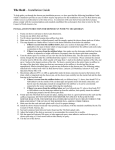
1
INSTALLATION
PACKET
Always consult the following installation instructions as well as the CAD
diagrams when installing your fence.
Page 1 of 10
IMPORTANT
GENERAL POST INSTALLATION
When installing your fence or gate, we recommend a minimum of 2" clearance between the bottom of the panel and the ground. This will allow enough clearance for the gate to swing freely.
Measure, assemble and install your gates first (even pre‐cut gate kits). The installed gate will set the height of the fence being installed. Failure to do so may result in a poor installation. Dry fit the cut rails into gate socket posts. Make any needed adjustments prior to gluing your gates. For various reasons, gate sizes may vary in width.
Survey land for special features such as obstructions, underground cables, or concrete from the old fence. Be sure to 1
follow all local building codes and obtain a building permit if necessary. Contact your local utilities prior to digging.
Install the line stakes (secure stakes firmly) and run a string line 1.5" to 2" off of the ground, (see figure 3 located on page 2.) 2
Line should not be distorted. Avoid tall grass, weeds and other obstructions. The line should be very tight!
Use a tape measure to measure and mark where the posts are to be installed. Most of the posts are to be installed 72" or 96" 3 from center of post to center of post. The Semi‐Privacy panels will have a 97" from center of post to center of post layout. Always follow the information on your C.A.D. diagram.
Remove string line leaving the stakes and dig the post holes. For 5" posts you will need a 12" dia. hole and for 4" posts you will need 10" dia. hole. Accuracy in the depths will help to simplify 4 post installation. Run a string line on side of posts to insure fence line is straight. See figure 1. NOTE: Recommended depth of holes is 30" ‐ 36". Check local codes and frost lines as greater depth may be required.
We recommend installing 1 post and 1 section at a time but there are many methods to install. As long as the end result is positive, feel free to alter this method to suit your installation needs. Concrete and plumb the first post and insert assembled 5
panel rails into the first post. Next, have the second post sitting in the adjacent hole, insert assembled panel rails into the second post, then concrete and plumb. Repeat for all panels and posts. To insure a quality job, it is strongly recommended that all posts be set in concrete. To do this, hold post in place to prevent slippage. Fill remainder of hole around post with concrete to 3" below ground level. Be sure to work concrete into hole around 6
post as needed. We recommend you mix concrete and pour wet. Use a minimum of 2 of the 80 lbs. bags of quickcrete for each 5" post and 2 of the 60 lbs. bags for each 4" post. Recommended: drill holes (1/4" bit) through the underside of rails to allow water to escape. If your bottom rails have ribs as shown in figure 2, you will need a bit long enough (1/4"x4") to drill through the upper rib. Recommended: If you are filling the 7
inside of your post with concrete you must drill holes to prevent sagging.
Page 2 of 10
•
•
HELPFUL HINTS:
HIGH WIND INSTALLATION
If post does not already have a concrete hole from the factory, drill a hole at least 3/4" dia. 12" up from bottom of post. This will help concrete get into post.
When gluing picket caps, place a thin bead of glue inside the picket and press picket cap into place.
If the fence is over 6' tall or you are Post caps should not be glued in the event you want to upgrade to a different style. A small amount of clear silicone on the inside corner of post cap will secure cap to post.
with concrete AFTER THE PANELS ARE •
located in a high wind area it is mandatory that you will fill the inside of the posts at least 22" above grade INSTALLED. Prior to installing panels •
Clean fence using a formula of 1/3 Cup powdered detergent, 2/3 Cup household cleaner and 1 gallon water. Rinse thoroughly.
into the posts tape the lower rail to prevent concrete backflow.
•
For stain removal use either lacquer thinner or soft scrub with bleach. Rinse thoroughly with water after using either of these.
INSTALLATION STEPS
Solid Privacy – All heights
3
Follow instructions for digging holes and layout.
Install 1 post (post A) with concrete around the post – level and plumb.
Have another post (post B) sitting in the adjacent hole.
4
Install the bottom and top‐rail in post A.
5
Slide the T&G pickets between the bottom and top‐rail (don't forget the U‐channel on first and last pickets).
1
2
6
7
8
Install the bottom rail in post B.
Install the top rail in post B.
Put concrete around post B and level and plumb.
Solid Privacy with Lattice – All heights
1
2
3
4
5
6
Follow instructions for digging holes and layout.
Install 1 post (post A) with concrete around the post – level and plumb.
Have another post (post B) sitting in the adjacent hole.
Install the bottom and mid‐rail in post A.
Slide the T&G pickets between the bottom and mid‐rail (don't forget the U‐channel on first and last pickets).
7
Install the bottom rail in post B.
Install the top rail in post A.
8
“Slide” the lattice strip between the mid‐rail and the top rail (don't forget the lattice end channels).
9
Install the mid‐rail and top rail in post B.
Put concrete around post B and level and 10 plumb.
Page 3 of 10
Solid Privacy Closed Spindle Top 1
2
3
Follow instructions for digging holes and layout.
Install 1 post (post A) with concrete around the post – level and plumb.
Have another post (post B) sitting in the adjacent hole.
5
Install the bottom and mid‐rail in post A.
Slide the T&G pickets between the bottom and mid‐rail (don't forget the U‐channel on first and last pickets).
6
Install the bottom rail in post B.
7
Install the top rail in post A.
Put the pickets in the holes between the top rail and the mid‐rail.
4
8
9
Install the top rail and mid‐rail in post B.
Put concrete around post B and level and 10
plumb.
11
Repeat down the fence line.
Solid Privacy with Mid Rail – All heights
1
Follow instructions for digging holes and layout.
2
Install 1 post (post A) with concrete around the post – level and plumb.
Have another post (post B) sitting in the adjacent hole.
3
4
5
6
Install the bottom and mid‐rail in post A.
Slide the T&G pickets between the bottom and mid‐rail (don't forget the U‐channel on first and last pickets).
7
Install the bottom rail in post B.
Install the top rail in post A.
8
Slide the T&G pickets between the mid‐rail and the top‐rail (don't forget the U‐channel on first and last pickets).
9
Install the mid‐rail and the top‐rail into post B.
Put concrete around post B and level and plumb.
12 Repeat down the fence line.
11
Semi ‐ Privacy and Pool styles that have a middle rail (5' or taller).
1
Follow instructions for digging holes and layout located on page one.
2
Install 1 post (post A) with concrete around the post. Level and plumb.
3
Have another post (post B) sitting in the adjacent hole.
4
5
Insert the bottom and middle rails into post A. The middle rails will have routed holes on the top and bottom of the rail. The larger routed holes should face towards the ground.
Insert the bottom and mid‐rails in post B.
6
Insert the top rail into post A with the opposite end (at post B) upward towards the sky at an angle.
7
Slowly insert the pickets one at a time as you lower the rail into place.
8
As you near the last few pickets it will be necessary to pull post B outward to insert the top rail.
9
Put concrete around post B and level (horizontal) and plumb (vertical).
Repeat the above method down the fence line.
10
Pool styles with no middle rails.
1
2
3
4
5
6
Follow instructions for digging holes and layout located on page one.
Install 1 post (post A) with concrete around the post. Level and plumb.
Have another post (post B) sitting in the adjacent hole.
Assemble the panel using rails and pickets. The rail with aluminum is the bottom rail.
Insert the rails of the assembled panel into post A first. Then, insert the rails of the assembled panel into the opposite post, (post B)
Put concrete around post B, level and plumb the post. Repeat the above steps down the fence line.
Page 4 of 10
Picket styles‐ pickets go through the top rail.
1
2
3
4
5
6
Follow instructions for digging holes and layout.
Install 1 post (post A) with concrete around the post. Level and plumb.
Have another post (post B) sitting in the adjacent hole.
Insert the bottom and middle rails into post A. The middle rails will have routed holes on the top and bottom of the rail. The larger routed holes should face towards the ground.
Install the bottom rail in post B.
9
Install the top rail in post B.
Put concrete around post B and level and plumb.
Repeat the above method down the fence line.
After all rails installed, slide the pickets through the rails. 10
Glue on picket caps.
7
8
PANEL ADJUSTMENTS
"CUTTING DOWN THE RAILS"
Under many conditions panels may be "cut down," or reduced in length. Please consider the following information and
suggestions regarding these particular styles of fence:
Privacy Fence - the privacy panels include 6" wide T&G pickets, it is best to reduce the length of the panel in increments
of 6". If you do not follow this course, you may have to "rip" the length of the picket, which would likely require the use of a
saw. Once you have determined the actual length of panel needed, cut only one end of the rails to achieve the desired
measurement. Note: The middle and top rails of the "picket top style fence" will likely need to be cut at both
ends.
Picket Fence - Both ends of rails may need to be cut down to have the pickets fit uniformly between posts. Be sure to cut
the top and bottom rails the same to insure proper picket alignment. When eliminating pickets from a "scalloped" panel,
remember that you will have to insert the pickets in such a way that it resembles the scallop, or slope of the original
panel.
SECURING SHORTENED PANELS
In instances where rails must be cut down, try to cut material from one end only when possible as this will ensure that
you replace only one set of notches. After cutting any rail, you will need to make accomodations to replace the notches
that you have removed. Notches are required on the ends of the rails to keep the rail snugly secured inside the post.
OPTION 1 ( RECOMMENDED)
After the rails are installed, insert a screw at each end of
the rail on the face of the rails, outside of the post. (See
figure 4). We recommend a small pan head size number
12 stainless steel screw. After the screws are installed
you may want to paint it to match the color of your
material. You can use standard spray-paint or you may
even use auto touch up paint found at your local auto
parts store. Snap caps can be purchased at www.prodec.com
OPTION 2
If option 1 does not fit your needs you may want
to consider this option. A simple method for
replacing notches on the top rail is to drive a
stainless steel screw into the rail through the
opening in the top of the post. See Figure 5. This
will make certain that the top rail remains inside
the post if force is applied to pull it out. A method
for replacing the notches on a bottom rail also
utilizes a stainless steel screw. Instead of driving
the screw partially into the top wall of the rail,
insert it fully into the front face of the rail as close
to the end as possible. See Figure 6. While
simultaneously inserting the rail into the post, use
applied pressure from your thumbs to deflect or
"bow in" the face of the rail enough so that the
head of the screw passes through the routed
opening of the post. This method will also ensure
Page 5 of 10
that the top rail remains inside the post if force is
applied to pull it out.
GATE ASSEMBLY INSTRUCTIONS
ASSEMBLY OF PRIVACY GATE
1
Always start by doing a "Dry Fit" test without gluing. This allows
you to make any necessary adjustments. Start the assembly by
inserting the rails into the first gate socket post as shown. Install
a u-channel on the first picket Feed the pickets into the slots of
the rails. Continue installing the additional pickets.
2
Once you have finished installing the pickets, install the remaining Uchannel in the same manner as the first. Do not use glue for the initial
"Dry Fit" assembly. Once assemly is complete measure to be sure gate
is the same width at top and bottom.
3
Cross measure the gate. Be sure to read the same side of the
tape rule. Failure to do so will result in the wrong measurement.
4
Leaving the panel assembled, carefully remove the rails from the socket
posts. Turn the first socket post up and run a 1/8" bead of vinyl glue
(included) around the inner rim of the socket approx. 1/4" down
5
After the glue is in the pockets of the first gate post, flip it down
and quickly insert the rails into the pockets. Be sure to firmly
insert the rails. The adhesive will set in about 45-60 second.
6
Quickly repeat steps 5 & 6 for the other post. This may take some
assistance to do before the adhesive begins to set.
7
Quickly measure the top and bottom of the gate as shown here.
Both measurements should be equal.
8
Allow glue to dry for 1 hour, cut and install the angle brace. The brace
should run at an angle starting at the lower corner of the gate on the
hinge side and run at an upward angle towards the top of the gate on
the latch side.
9
Pre-drill two holes into each end of the angle brace only. DO NOT
Pre-Drill into the gate. Attach the angle brace using two of the
provided self-tapping screws at each end of the gate.
Page 6 of 10
ASSEMBLY OF PICKET GATE
1
Start gate assembly by locating all parts to the gate: Socket
posts, rails & pickets. Using NO GLUE, assemble for a "dry" test.
2
Once the gate is assembled, measure the width at the top and bottom
of gate as shown here. They must be the same width or your gate will
be out of square!
Note: If you are assembling a pool or a semi-privacy style gate you must
have the pickets in place prior to gluing the gate.
3
5
Measure diagonally as well. Both ways should be the same or
within 1/8" difference at most! Make any adjustments for gate
before moving forward.
After the glue is in the pocket of the first socket post, flip it down
and quickly insert the rails into the pocket. Move on to the next
step quickly! Be sure to firmly insert the rails, the adhesive will
set in about 45 seconds.
7
Quickly, measure the top and bottom of gate as shown here.
Both measurements should be the same.
9
After pickets are installed, lay the angle brace on the gate and
mark the length to cut. The brace is to be mounted to the rails
only, (see pictures below) Pre-drill 2 holes into the angle brace only.
DO NOT pre-drill into the gate. The angle brace should run at an
angle starting at the bottom of the bottom rail near the bottom
hinge and run at an angle towards the top of the top rail of the
latch post.
4
After the gate has been checked carefully remove the rails from the
gate posts. Flip first gate post up and insert a 1/8" bead of glue
around the inside of the pocket down about 1/4" from top of the
pockets.
6
Quickly repeat the step above for the other post. This may take some
assistance to do before the adhesvie sets.
8
After gate has set for 24 hours, insert the pickets through the top rail
into the bottom rail as needed. NOTE: This will have already been
done on a pool or semi-privacy style gate.
10
►►►►►►►►►►►►►►►
11
Attach the brace using 2 self-taping screws at each end of the
gate as shown here. The screws are provided. Note: Mark the
hinge side of socket post with tape. This will keep you from
installing the angle brace in the wrong direction.
Page 7 of 10
GATE INSTALLATION INSTRUCTIONS
The following is based on an assembled gate that is properly sized for opening.
SINGLE GATE INSTRUCTIONS
A.
B.
C.
Determine the direction the gate is to swing, usually swings into yard. Be sure to check your local codes!
If you have aluminum post inserts, install prior to the installation of the gate. If you do not have inserts you must fill the hinge post with concrete and rebar after the gate installation.
Locate and follow hardware installation instructions.
The gate will be mounted to be flush with the
side of the fence that the gate will be
swinging. See the illustration to the right. Be
sure the gate will be high enough to clear
obstructions such as snow. The gate posts
should be cut on site as needed. Some
installers cut the gate posts off at the bottom
of the bottom gate pocket. DO NOT cut into
the gate pocket.
DOUBLE GATE INSTRUCTIONS
Typical gate installation based on an assembled gate that has been properly sized for the opening
A.
B.
C.
D.
Follow the same instructions as per a single gate when installing the hinges for both gates.
To calculate the variances for the latch you must treat the fixed gate as if it were a standard fence panel. The ideal hardware installation on a double gate should have equal spacing between posts and gates.
Install the Drop Rod to post of the fixed gate. HIGH WIND INSTALLATION INSTRUCTIONS
FOR PRIVACY PANELS
All of our vinyl privacy panels ( up to 6' in height ) have been tested and certified to achieve high wind loads. In order to meet the wind rating
requirements, the panels must be installed as noted below. These steps are the same steps used for the certification and must be
followed exactly the same as used in testing. We tested the full privacy panels as the lowest common denominator.
ALL PRIVACY PANELS
After the fence is installed, all posts are to be filled with "Quickrete" brand of concrete to at least 22" above the ground ( inside the post ) as shown
in the following figure 1 drawings. Next, install the screws on the back side of the panel ( the side you will not see ) using #10 x 1" self-tapping
Page 8 of 10
stainless steel or galvanized pan head screws which can be purchased from your local hardware store. Be careful not to overtighten or strip
the screws. Every picket will have one screw at the top rail and at the bottom rail on one side of the fence only. Every rail will have one screw
installed on each end of the rail "Inside" the post as shown on the following drawings as Figure 2.
SELECT YOUR PANEL
STYLE FROM THE
FOLLOWING
DRAWINGS FOR AN
ILLUSTRATION OF THE
SCREW PLACEMENT
FOR THE HIGH WIND
INSTALLATION.
Page 9 of 10
* Purchaser has the sole responsibility to determine whether these products comply with applicable codes and is appropriate for the intended use. The purchaser and installer
should review the intended use of the products with a licensed professional engineer to determine code compliance and intended use.
Page 10 of 10