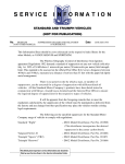
1
OWNER’S MANUAL
INSTALLATION -OPERATION -MAINTENANCE
Standard Pump System
Powered By: Bennett Hydraulics
CAUTION:
Read this instruction
manual carefully. Become familiar with the
controls and know how to operate the
Power-Pole™system safely.
US Pat No. 6,041,730
1
FIVE (5) YEAR LIMITED WARRANTY
(KEEP YOUR RECEIPT) ORIGINAL PURCHASE
Any Power-Pole™ manufactured by JL Marine systems Inc. is warranted against defects
in material and workmanship in the stern bracket, U-channel, Knuckle joint, hydraulic
system, and electrical system, according to the following stipulations:
1.
2.
3.
4
5.
6.
7.
The Power-Pole™ is warranted to the original owner for a period of five years, from
the date of purchase.
A.
A Power-Pole™ component which proves defective within ninety (90) days from
date of purchase will be repaired or replaced, at JL Marine Systems, Inc. option,
free of charge to the owner. JL Marine Systems, Inc. will pay for the replacement
product shipping and handling fees to and from the JL Marine Systems, Inc.
manufacturing plant or some other place which JL Marine Systems, Inc. might
designate.
B.
A Power-Pole™ component which proves defective after twelve (12) months,
but before sixty (60) months, will also be repaired or replaced free of charge, but
there may be a shipping and handling charge to and from the JL Marine systems,
Inc. manufacturing plant or some other place which JL Marine Systems, Inc.
might designate. In the case of replacement, parts of same (or equivalent) model
will be used.
This warranty covers the finish for a period of six (6) months from the date of purchase not to crack, chip or fade.
This warranty covers the hydraulic pump and cylinder for a period of (36) months.
Pump damage due to submersion or excessive exposure to water may void this
warranty.
Power-Pole™ warranties are activated upon receipt by JL Marine Systems, Inc. of
the completed warranty card, postdated within 10 days of purchase. Please retain
your sales receipt as proof of purchase.
This warranty is void if the Power-Pole™ is used commercially, structurally
altered or subject to stress beyond the physical limits of the anchor material.
This warranty does not cover abrasion or abnormal abuse, nor does it cover an anchor while being used for anything other than what it was intended for.
JL Marine Systems, Inc. reserves the right to change products and designs without
incurring any obligations to incorporate such changes in already completed products,
or those in the hands of dealers or consumers. Anchors repaired or replaced under
this warranty may or may not have these changes.
THE WARRANTY CONTAINED HEREIN IS THE EXCLUSIVE WARRANTY MADE
BY JL Marine Systems, Inc. AND THERE ARE NO OTHER WARRANTIES, EXPRESSED OR IMPLIED, INCLUDING A WARRANTY OF FITNESS FOR A PARTICULAR PURPOSE OR OF MERCHANTABILITY MADE WITH RESPECT TO
SUCH ANCHORS.
JL Marine Systems, Inc. IS NOT LIABLE FOR ANY INJURY OR MISHAPS SUSTAINED IN THE USE OF THIS PRODUCT. THE USER OF THIS PRODUCT ACKNOWLEDGES ASSUMED RISKS AND WAIVES ANY AND ALL CLAIMS
AGAINST JL Marine Systems, Inc. AND ANY OF IT’S AGENTS.
This warranty applies under conditions of normal use. The warranty does not cover: 1)
defects caused by improper assembly or disassembly; 2) defects occurring after purchase
due to product modification, intentional damage, accident, misuse, abuse, negligence or
exposure to corrosive elements; 3) cosmetic damage and 4) labor or assembly costs.
Except as provided herein, JL Marine Systems, Inc. makes no express warranties, and any
implied warranty, including without limitation any implied warranty of merchantability or
fitness for a particular purpose, is limited in its duration to the duration of the written
limited warranty set forth herein.
Except as provided herein, JL Marine Systems, Inc. shall have no liability or responsibility
to the purchaser or any other person or entity with respect to any liability, loss or damage
caused or alleged to be caused directly or indirectly by use of the product, including, but
not limited to, any incidental or consequential damages. Some states do not allow limitation
on how long an implied warranty lasts or the exclusion of limitation of incidental or
consequential damages, so the above limitation and exclusion may not apply to you.
This warranty gives you specific legal rights. You may also have other rights which vary
from state to state.
2
Warranty Procedure
To obtain warranty service, take or ship your Power-Pole ™ to
JL Marine Systems, Inc or to a JL Marine Systems Inc. authorized service station, together with a note describing your complaint and your copy of the dated purchase receipt. If you
choose to ship your Power-Pole ™ to JL Marine or an authorized service station, all shipping arrangements must be made by
you and all shipping charges and insurance must be fully prepaid. All to and from shipping charges for JL Marine systems,
Inc. products which have been serviced under this Warranty
within ninety (90) days of the purchase date may be reimbursed
by JL Marine.
Keep this information for your records
Model
Serial No
Customer’s Name
Place of purchase
Date of Purchase
JL Marine Systems, Inc.
9208 Palm River Road suite 303
Tampa, FL 33619
(813) 689-9932
3
CONGRATULATIONS on your purchase of a Power-Pole™ Shallow Water Anchor system. It has been designed, engineered, and manufactured
to give you the best possible dependability and performance for years of
enjoyment.
Please read and retain this manual. The information contained
in the manual describes the proper procedures for safely
installing, operating and maintaining your Power-Pole™.
CAUTION: Do not use the Power-Pole™ as your primary
anchorage. Never leave your boat unattended while anchored with the Power-Pole™ .
TRAINING:
•
Read this operator’s manual carefully. Become familiar with the controls and know how to operate your Power-Pole™ properly.
•
•
•
Do not allow children to operate the Power-Pole™ without adult supervision.
Do not modify the unit in any way or add accessories not intended for this unit.
Always disconnect power from Power-Pole™ before servicing.
PREPARATON:
•
•
Always make sure the Power-Pole™ is in the full up position with a travel strap in place when on the trailer.
If any debris gets caught around the Power-Pole™, DISCONNECT power from motor and remove any debris.
OPERATION
•
In the event of pump failure the Power-Pole™ may be manually raised by applying enough pressure to bypass the PoleProtector valve thus allowing the unit to come all the way up to the stowed position. If the Power-Pole™ is beyond reach it
can be forced up by driving the boat to shallower water. Depressing the up button on the Power-Pole™ control may offer
assistance.
•
•
•
•
•
•
•
Be sure to have the Power-Pole™ in the full up position when using outboard motor at high speeds.
Keep your hands and clothing completely clear of the Power-Pole™ at all times.
Do not use the Power-Pole™ as a step or handle to enter or exit the boat.
Never allow children to play with or around the Power-Pole™.
The Power-Pole™ is fully powered, never give any assistance to raise or lower.
In high wind or rough seas the Power-Pole™ may relieve holding pressure to protect your boats transom
Never leave your boat unattended while your Power-Pole is providing anchorage.
MAINTENANCE AND STORAGE:
•
CAUTION—Hydraulic lines always have pressure, disconnecting the lines will cause sudden high pressure leakage and
Power-Pole™ failure which may cause bodily harm.
•
•
•
Check all hydraulic lines at frequent intervals for proper tightness to be sure there are no leaks.
•
•
•
Check all hydraulic lines at frequent intervals for possible chaffing or damage from kinking or abrasion.
Make sure all power connections are secure and free of corrosion
Check all nuts, bolts, and screws at frequent intervals for proper tightness to be sure Power-Pole™ is in safe working condition.
Keep the hydraulic reservoir filled within the indicator marks at all times
Thoroughly rinse and lubricate all moving parts after each use.
4
INSTALLATION
Tools and Materials Needed
1.
2.
3.
4.
5.
6.
7.
8.
9.
10.
11.
12.
13.
14.
7/16”, 1/2” & 9/16” Wrench
7/16”, 1/2” & 9/16” Socket and Ratchet
Electric Drill
Four Foot Straight Edge
Marine Grade Sealant
Tape Measure
Wire Cutters
Razor Tube Cutter
Small Funnel
Wire Crimpers
5/16” & 5/32” Drill Bits
1 Quart Automatic Transmission Fluid
#1 & #2 Phillips Head Screw Drivers
Jig Saw or Rotary Saw
Hardware Included
a.
Qty(4) 5/16 x 3.5” all-thread
transom mount bolts
b.
Qty(1) 5/16 x 3.5” cylinder ram
bolt
c.
Qty(2) cylinder ram spacers
d.
Qty(2) thru hull bushings
e.
Qty(1) Cylinder end cap bushing
f.
Qty(3) marine wire ties
g.
Qty(4) 5/16 fender washers
h.
Qty(4) 5/16 lock nuts
i.
Qty(4) neo-bond washers
j.
Qty(2) cylinder ram bolt washers
k.
Qty(2) Brown cylinder ram bolt
bushings
l.
Qty(1) 5/16 low profile locknut
m.
Pole-Protector valve
a
b
d
c
k
l
i
5
f
j
g
h
e
m
INSTALLATION
Hydraulic Power Unit Included
1
2
3
12
4
5
6
11
10
7
9
DIAGRAM #
8
Description
Fig (1)
Part Number
1
Type 25 thread cutting screw
2
Solenoid valve
VP1154
3
Pole Protector Connector
VP1955
4
1/8” NPT to 1/4” tube connector (To
cylinder base)
VP1146
5
1/8” NPT to 1/4” tube connector (To
cylinder end)
VP1146
6
Fill indicator
7
Wire Harness (22’)
8
Quick-disconnect plug
9
Filler Stack and Plug
10
Motor Strap
11
Mounting bracket for HPU
12
Lexan Cover
VP1135-R (Red)
VP1135-G (Green)
WH1000
VP1143
H1180
VP1142
H1179
VP1138
6
INSTALLATION
Parts Included
14
13
23
15
16
22
17
21
20
18
19
Fig (2)
DIAGRAM #
Description
Part Number
13
Top Arm (Inside)
PP1015
14
12” Hydraulic Cylinder
15
1/4” Hole, (Marks bottom of Arm)
16
Stern Bracket
PP1017
17
Serial Number keeper plate
PP1018
18
1/4” Hole, (Marks bottom of Arm)
19
5/16 Hole for Hydraulic Mount
20
Bottom Arm (Outside)
PP1016
21
5/8” Everflex™ spike
PP1019
22
Spike Bushing
PP1020
23
Top Knuckle
PP1021
7
HL12CDA
INSTALLATION
Mechanical Schematic
HPU# JLDL12DA
Preset at
550 PSI
Hydraulic Power Unit
Brass jumper
Fig (3)
8
INSTALLATION
Section 1 Choosing the Location
****IMPORTANT**** Carefully consider and physically
check all 5 steps in section one before mounting the
stern bracket.
Boat Position in Wind
Boat doesn't interfere
with back cast for right
handed caster
1) “Left or Right” side of the
boat?
Right-handed caster should put the
Power-Pole™ on the right side and lefthanders should be on the left side. This is
especially important when fly-fishing. The
boat will pivot in the wind to the proper
angle for easy downwind casts without
the back-cast being over the center of the
boat.
Fig (4)
2) Vertical Positioning—no trim
tabs
Use a straight edge on the bottom
plane of the boat directly below and
centered from the Stern Bracket. Mount
the Power-Pole™ so that the Bottom Arm
mounting point of the stern bracket is 4”
above the straight edge.
Fig (5)
3) Trim Tab Clearance
If your boat has trim tabs it is very important to check their clearance requirements
before mounting the bracket. For example, when the bracket is mounted at the
suggested 4” above the bottom plane of
the boat it will have about 11.5” of clearance for trim tabs. If your Trim Tabs are
12” and you are mounting the bracket over
them, then you must mount it at least 5”
above the boat’s bottom plane rather than
the suggested 4”. Standard 9” Trim Tabs
do not interfere with the Power-Pole™.
Fig (6)
9
INSTALLATION
4) Obstructions
Look inside the boat along
the transom to make sure that
the bolts will not have any
obstructions.
5) Motor Clearance
Turn the motor all the way in the
direction of the Power-Pole™
then lower to make sure the
motor does not interfere. Spin
the propeller to make sure it has
clearance also. Allow a minimum
of 3” between the motor and the
Power-Pole at all times in any
position. See fig (7)
Fig (7)
Section 2-Mounting The Stern
Bracket
Hardware list for this step
A
B
C
D
Qty(4) 5/16 x 3.5 all-thread bolts
Qty(4) 5/16 Neo-bond rubber backed washers
Qty(4) 5/16 fender washers
Qty(4) 5/16 locknuts
Once a location has been chosen, mark all
four holes. Before drilling any holes double
check the inside to be sure that the bolts are
not going to interfere with anything and that
you have plenty of room to tighten the nut on
the other side.
Once all four holes are marked and drilled,
fasten the Stern Bracket using the listed
hardware. The rubber backed washers are to
protect the powder coated surface of the
Fig (8)
stern bracket. Use a marine quality sealant
on and around the bolt and holes then tighten
adequately, DO NOT OVER TIGHTEN.
10
INSTALLATION
Section 3-Hydraulic Power Unit (HPU)
Install the (HPU) In a convenient location and in a dry environment.
Important: The HPU must be mounted in a dry enough location
to avoid submersion and drenching. Allow space above the HPU so
that it may be slid into its mounting bracket (about 3"). Layout upper
holes on HPU mounting bracket 4-5/8" apart and start #10 x 1"
screws using 5/32" pilot holes. Then drill 5/32" pilot holes for lower
screws and mount bracket. Slide HPU into bracket.
Section 4-Installing the Lines and Cylinder
Unpack the hydraulic cylinder from the box with the two 90° nickel plated push-fit
hydraulic line connectors pre-installed.
Insert the 1/2” long bushing into the 5/16 hole in the
RED end cap (found in the Power-Pole™ hardware
bag). Install on the same side as the hydraulic fittings. See fig (9b)
Fig (9a)
Partially remove the 1/4” x 3 1/2” bolt on the top of the
stern bracket and install the cylinder. The hydraulic
fittings should be on the same side of the
Power-Pole™ as the serial# plate.
Attach the hydraulic lines to the push-fit connectors by
simply pushing the line into the fitting. “no tools required”. Route the top line down the cylinder and secure with the enclosed marine wire straps. Route the
bottom line directly down and thru the serial# plate.
Fig (9b)
Continue to route each line behind the Serial plate
and into the boat. See fig (9a) The lines can either go
through or over the transom whichever you prefer. Two through hull sleeves are
included to make a clean transom penetration.
Cover the ends of the tubing with tape during the installation to prevent any debris
from getting in the lines and contaminating the oil. The slightest piece for dirt could
cause severe problems.
***Note: With the Power-Pole™ in the full up position pull any slack from
inside the u-channel, this will prevent the hydraulic lines from jamming when
lowing the Power-Pole™.
11
INSTALLATION
****IMPORTANT**** Once the lines are routed behind the
serial# plate and connected to the push fit
connectors move the cylinder through the entire
range of motion to make sure the lines are not
going to kink, chafe or otherwise be damaged
during normal use.
Install the Pole-Protector valve as indicated in fig. (10) then route
the lines from the Power-Pole™ to the HPU through the most convenient and direct way. Attach with clips and hose benders wherever necessary. COVER THE ENDS OF THE TUBING TO PREVENT CONTAMINATION FROM ENTERING THE SYSTEM WHILE
ROUTING THE LINES THROUGH THE BOAT.
Make sure the line that has the Pole-Protector in it is attached to the
base side of the hydraulic cylinder.
See fig (10)
Hydraulic
Power Unit
PoleProtector
Hydraulic
Cylinder
HPU
Top
Fig (10)
Base
12
INSTALLATION
Section 5-Choose Location for Switch
The control switch should be mounted where it is easily accessible from
anywhere on the boat.
Remember the switch requires a +12v DC
supply with a minimum of 12 AWG wire. If the switch is mounted in the
bow of the boat you should use 10 AWG wire. Multiple switches can
also be installed.
Section 6- Mounting Switch
Mark the cutout area and allow room for the faceplate screws. Check to
make sure you are not going to interfere with anything on the other
side. Use a jig saw to cut out the marked area then screw in place.
Section 7-Connect Wires
***IMPORTANT*** The +12v source should be directly from the battery with a minimum size of 12 AWG wire. If an inadequate wire is used
the Power-Pole™ may not function properly.
Fig (11)
Remove this cutout from your manual and tape to your console at the
desired switch location. Using a fiberglass cutting blade cut the solid
line. Try to remove all the line without going outside the dashed line.
13
INSTALLATION
Section 9-Prime Pump
After all lines are completely installed, remove the plug from filler stack
located at the front left corner of the reservoir. Fill reservoir to “Full
Line” using any type automatic transmission fluid (ATF).
Using the control, cycle the cylinder from all the way out to all the way
in several times to clear all the air from the system. No bleeding is necessary. To prevent the cylinder from scaring the inside of the u-channel,
wrap the end of the ram with a soft cloth during this step.
Section 10-Final Assembly
1) Using the 5/16 x 3.5” bolt attach the cylinder ram to the Uchannel as shown.
Hardware list for this step
A.
B.
C.
D.
E.
F.
Qty (1) 5/16 x 18 x 3.5 bolt
Qty (2) 5/16 thin wall washer
Qty (2) 5/16 brown bushing
Qty (1) 5/16 low-profile lock nut
Qty (1) small ram spacer
Qty (1) large ram spacer
*NOTE* The large spacer goes on the same side of the ram as the
hydraulic fittings to offset the cylinder enough so that the lines do
not interfere with the u-channel.
14
IMPORTANT!!
REGISTER YOUR POWER-POLE™ Shallow Water Anchor
This warranty registration card must be completed and mailed to JL
Marine Systems, Inc. to validate your warranty.
CUSTOMER INFORMATION
Purchaser’s Name______________________________________ Age ___
Purchaser’s Address___________________________________________
City _____________________________State _________Zip___________
Boat type________________________________ Length ______________
E-mail_______________________________________________________
POWER-POLE™ INFORMATION
Date of Purchase: Month ________Day ______Year__________
Serial No. ___________________(Found on Stern Bracket)
Place of purchase ______________________________________
CUSTOMER SATISFACTION
Where did you hear about Power-Pole™?
Ο Television (show) _____________
Ο Word of Mouth
Ο Internet
Ο Advertisement (type)___________
Ο Other_______________
What type of fishing do you prefer?
Ο Redfish, Snook and Trout
Ο Bone Fish
Ο Tarpon
Ο Bass
Ο Other________________
What is your favorite feature?
Ο Quiet
Ο Convenience
Ο Boat Control
Ο Holding Power
Ο Other_______________
What is your favorite bait?
Ο Live Bait
Ο Cut Bail
Ο Artificial
Ο Fly
15
16
9208 Palm River Rd, suite 303
Tampa, FL 33619
JL Marine Systems, Inc.
postage
Post Office will
not deliver
without proper
Place
First-Class
Stamp
Here