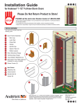
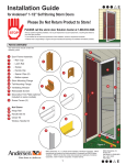
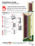
1
Installation Guide U for Andersen® 1-1/4” Self-Storing Storm Doors with Balanced Retractable Insect Screen Please Do Not Return Product to Store! PLEASE call the storm door Solution Center at 1-800-933-3626, with any questions regarding installation, lost part replacement, or anything else related to your storm door purchase. Read this entire guide before you begin your installation. If your abilities do not match the requirements of this installation, contact an experienced contractor. PARTS OVERVIEW Your installation kit should contain the following parts. However, in some door models, not all of the parts will be used. A Rain Cap B Door Frame C Rain Cap Extender D Ventilating Glass Panel E Hinge Rail with 4 hinges A I G J T A B H (Hinge Side Z-bar) F Insect Screen G Latch Rail F C (Handle Side Z-bar) H Sweep I Side Screw Covers (2) J Top Screw Cover (1) K Hinge Rail Shim Not Shown L Preload Clip M Installation Kit I D J E E K (Pink, Clear & Green Parts Bags Inside) N Handle Set Kit (Blue Parts Bag Inside) O Latch Side Spacer Clip P Sill Spacer Clip Q Cover Plate and Drill Kit R Window Handle Kit S Slot Cover T Top Cover Plate G Figure 1 Andersen Storm Door Division is a wholly owned subsidiary of Andersen Corporation. Andersen Storm Door Division manufactures and supports the limited warranties for Andersen® and EMCO® storm doors. “Andersen” and “EMCO” and all other marks where denoted are trademarks of Andersen Corporation. ©2014 Andersen Corporation. All rights reserved. 1 H Andersen SDD, PO Box 853 Des Moines, IA 50306-0853 Rev 1-2014 12088 Print in Color p/n 621791 SAFETY FIRST: Please read and follow all Cautions and Warnings in this guide. WARNING WARNING Metal fasteners and other hardware components may corrode when exposed to preservative treated and fire-retardant treated lumber. Obtain and use the appropriate size stainless steel fasteners and hardware as called out by the installation guide to fasten unit to any rough opening made from pressure treated and fire-retardant treated lumber. Failure to use the appropriate materials for the installation may cause a failure resulting in injury, property or product damage. Entry door hardware and handle may become hot when exposed to sunlight. WARNING Improper use of hand or power tools could result in injury and/or product damage. Follow equipment manufacturer’s instructions for safe operation. Always wear safety glasses. WARNING WARNING Windows and doors can be heavy. Use safe lifting techniques and a reasonable number of people with enough strength to lift, carry, and install window and door products to avoid injury and/ or property damage. The insect screen is intended for reasonable insect control and not the retention of objects or persons within the interior. The insect screen material will not stop a person from falling through the door. RECOMMENDED TOOLS Phillips Screwdriver Drill Tape Measure Flat Tip Safety Glasses Pencil Scissors Hammer 1 Chisel Gloves Center Punch VERIFY MOUNTING REQUIREMENTS H Verify that the exterior brick mold, trim board or casing is firmly attached to the opening. The storm door will sag over time if the mounting surface is not sufficiently fastened to the entryway. To install the storm door, you must verify that the opening width, height and mounting surface are sufficient. W1 3/4” min 1. Measure the width at the top, middle, and bottom of the opening (Figure 2). Measure from the inside of the brick mold or exterior trim. Refer to Table 1. 2. Measure the height at the center of the opening. Measure from the inside of the brick mold or exterior trim, down to the top of the bottom sill. Refer to Table 1. Nominal Storm Table 1: Use this table to determine if your storm door will fit into the opening: Door Sizes ** Opening Sizes 8XJEUI * wYw w50w wYw w50w wYw w50w wYw w50w wYw w50w wYw w50w wYw w50ww 1” min H (height) W2 2 1/2” min Figure 3 w50w wUPw W3 3. Make sure that the brick mold or exterior trim meets the mounting surface requirements to install the rain cap, hinge rail and latch rail (Figure 3). You must have a minimum of: Figure 2 * * twNPVOUJOHTVSGBDFEFQUI twNPVOUJOHTVSGBDFGSPOU twIBOEMFDMFBSBODF * ** 'PSPQFOJOHXJEUITVQUPwXJEFSPSGPSNPVOUJOHTVSGBDFEFQUICFUXFFOwwQMFBTFDBMM PVS4PMVUJPO$FOUFSBUUPQVSDIBTFBTQFDJBMLJUUPBDDPNNPEBUFZPVSTJUVBUJPO Nominal storm doors sizes are listed. The actual storm door frame width and height will be less. &YBNQMF"OPNJOBMTJ[FPGwYwNBZIBWFBOBDUVBMTUPSNEPPSGSBNFTJ[FPGwYw 2 INTERIOR VIEW VISTA INTERIOR VUE DE L’INTÉRIEUR = EXTERIOR VIEW VISTA EXTERIOR VUE DE L’EXTÉRIEUR = i X VIEW VIEW 2 INSTALLATION PREPARATION Tools needed: K X a VIEW T LEFT HANDED A LA IZQUIERDA À MAIN GAUCHE b i VIEW RIGHT HANDED A LA DERECHA À MAIN DROITE 40 1/2” Figure 6 Figure 4 TO DOOR SILL HASTA EL BATIENTE DE LA PUERTA JUSQU’AU SEUIL DE LA PORTE Figure 5 1. Most homeowners prefer to have the storm In this step, you will determine the handle side of your storm door. 1. Left Handed (Figure 4): From the exterior, a left handed storm door will have the handle on the MFGUTJEFPGUIFTUPSNEPPS4FFQBHFTGPSJOTUBMMBUJPOJOTUSVDUJPOT 2. Right Handed (Figure 5): From the exterior, a right handed storm door will have the handle on UIFSJHIUTJEFPGUIFTUPSNEPPS4FFQBHFTGPSJOTUBMMBUJPOJOTUSVDUJPOT 3. The top interior is where the top cover plate (T) is located (Figure 6). c 2 1/2” X Determine if Hinge Rail Shim is needed Nominal Storm Door Sizes Shim needed if opening width is: wYwwYw w50w wYw w50w wYw w50w wYwwYw w50w wYw w50w VIEW K K IF REQUIRED SI FUERA NECESARIO SI NÉCESSAIRE Tape x4 1. Use the table above to determine if you need to use the provided hinge rail shim (K). 2. If your opening width falls within the dimensions listed, you will need to install the shim. (If JOTUBMMJOHBwUBMMTUPSNEPPSöSTUDVUPòwGSPNPOFFOEPGUIFTIJN If your opening width does not fall within these dimensions, proceed to step 3. 3. Remove any debris from the mounting surface where the hinge rail shim will be attached. 4. Apply the four strips of double stick tape from the pink bag to the shim, spacing them evenly along the entire length. Attach the shim to the mounting surface, as shown. 3 door handle on the same side as the entry door handle. In shallow door openings, this can cause the two handles to interfere. Check for potential interference using the rough measurements. If you anticipate that there will be interference, hand the storm door on the opposite side of your FOUSZEPPS4FFQBHF'JHVSFGPSEFUBJMFE hardware depth requirements. For a Right Hand Installation, go to Page 9. PREPARE STORM DOOR FOR INSTALLATION (Left Hand) 3 E Tools needed: H PINK BAG / BOLSA ROSA / SAC ROSE M P O i a VIEW i b VIEW 1/2” x8 1/2” Painted x2 i c VIEW E TOP PARTE SUPERIOR HAUT BOTTOM PARTE INFERIOR BAS T H CAUTION E PROFILE PERFIL PROFIL 1. Identify the top of the hinge rail (E). 2. Position the hinge rail along the hinge-side edge of the door frame so the bottom hole in the top hinge leaf lines up with the hole that has been predrilled into the edge of the door frame. NOTE: The top of the hinge rail should FYUFOEBQQSPYJNBUFMZwCFZPOEUIFUPQPG the door frame. 3. Attach all four hinge leaves to the door frame VTJOHVOQBJOUFEwTDSFXTGSPNUIFQJOLCBH in the installation kit. i d VIEW BOTTOM PARTE INFERIOR BAS BOTTOM PARTE INFERIOR BAS 1. Remove the entire clear protective film from the interior bottom of the door frame and properly discard. Peel up the first few inches from both bottom sides. e Do not drill completely through door. This will create an unnecessary hole in the door and may cause water and air infiltration. 1. Position the door sweep (H) so that it is centered across the width of the door frame and pressed tight against the bottom of the door frame. 2. $FOUFSQVODIBOEUIFOQSFESJMMwQJMPU holes at the bottom of the slot for future adjustment, then attach the sweep using QBJOUFEwTDSFXTGSPNUIFQJOLCBH i M VIEW 1/8” S O x2 1/2” H P 1. Install the sill spacer clip (P) under the latch side sweep screw and tight against the bottom of the sweep. Tighten the sweep screw to retain the sill spacer clip in place. 2. Install the latch side spacer clip (O) over the latch side of the door frame as shown. This DMJQTIPVMECFBQQSPYJNBUFMZwGSPNUIF bottom of the door frame. TOP PARTE SUPERIOR HAUT Q 1. Find the Cover Plate and Drill Kit (Q) located inside the door carton and identify the slot cover (S), BOEUIFDPMPSNBUDIFEwøBUIFBETDSFXT"MTPJEFOUJGZUIFwESJMMCJUGPVOEJOUIFQJOLCBH in the Installation Kit (M). 2. Hold the slot cover over the hinge side pocket of the door frame edge. Make sure hinge side pocket is fully covered by cover plate. Mark the two mounting screw locations. 3. 6TJOHBESJMMBOEwESJMMCJUESJMMBIPMFJOUIFNBSLFEMPDBUJPOT*OTUBMMUIFTMPUDPWFSXJUIUIF UXPwQBJOUFEøBUIFBETDSFXT 4 4 INSTALL HINGED STORM DOOR IN OPENING (Left Hand) Tools needed: A C YELLOW BAG / BOLSA AMARILLA / SAC JAUNE PINK BAG / BOLSA ROSA / SAC ROSE M x 19 1” 1/8” 3/16” Plug X a X b VIEW VIEW x1 i c VIEW O P 1. Set the door frame on the entry sill so the hinge rail is tight against the mounting surface or hinge rail shim (K) and the sill spacer clip (P) is sitting on the door sill. 2. Tip the top of the door frame into the opening, making sure that the sill spacer clip is still attached and resting on the sill. NOTE: Door may be out of square at this time. d 1. The door frame is properly seated in the opening when the hinge rail and latch side TQBDFSDMJQ0 BSFøVTIBHBJOTUUIFNPVOUJOH surface and the mounting surface completely fills the hole in the latch side spacer clip. If the latch side spacer clip hole is not completely filled, review step 2c. 2. 6TJOHUIFESJMMCJUGSPNUIFQJOLCBHBOEw screws from the yellow bag in the installation kit, fasten the hinge rail to the mounting surface. X OPPOSITE VIEW OTRO PUNTO DE VISTA VUE DE FACE VIEW 1. Open the storm door. 2. Pre-drill and fasten the hinge rail to the door KBNCVTJOHwTDSFXTGSPNUIFZFMMPXCBH 3. Remove both orange clips from the bottom of the door frame and properly discard. X e VIEW A 3/16” PLUG TAPÒN DE 0.31 CM BOUCHON PEINT 4,8 MM A C A E 1. Open the storm door. Place the rain cap (A) in the opening so that it rests on top of the hinge rail 2. 3. 4. 5. (E), aligning the end of the the rain cap with the edge of the hinge rail. Close the storm door. Adjust rain cap to achieve an even gap between the top of the door frame. Look at the center hole of the rain cap. If the mounting surface can be seen in the entire hole, proceed to step 4e. If the mounting surface cannot be seen in the entire hole, or if there is space above the rain cap, then remove the rain cap. 'SPNUIFNPVOUJOHTVSGBDFCBDL TJEFPGUIFSBJODBQDPNQMFUFMZJOTFSUBwQMVHGSPNUIF yellow bag into the middle hole. Re-install the rain cap as described above. 5 1. 6TJOHUIFESJMMCJUBOEwTDSFXTGSPNUIF yellow bag, fasten the rain cap to the mounting surface. 2. If a plug was installed in the middle hole, you will need to install the rain cap extender (C). 3. Place the rain cap extender over the rain cap BTTIPXOXJUICPUIFOETCFJOHøVTI 4. 6TJOHUIFESJMMCJUBOEwTDSFXTGSPNUIF yellow bag in the installation kit, fasten the rain cap extender to the mounting surface. 5 INSTALL LATCH RAIL AND REMOVE PROTECTIVE FILM (Left Hand) x6 Pad x3 1/8” Plug PAD ALMOHADILLA TAMPON 1. 'JOEUIFUISFFwTRVBSFBEIFTJWFCBDLFE spacer pads in yellow bag in installation kit. 2. 4XJOHEPPSPQFOBOEXJQFPòBOZSFTJEVF on edge of door. 3. 1FFMQBQFSCBDLFSPòFBDIQBEBOEBUUBDI them to latch side door edge. Position one BQQSPYJNBUFMZwEPXOGSPNUPQPGEPPS another close to center of door, and the UIJSEBQQSPYJNBUFMZwVQGSPNCPUUPN INSTALL HANDLE SET (Left Hand) a X b VIEW 6 1” M 1/8” X a YELLOW BAG / BOLSA AMARILLA / SAC JAUNE Tools needed: G 4. 5. against rain cap. Close storm door and slide latch rail towards door frame VOUJMJUDPOUBDUTBMMUISFFTQBDFSQBETDSFBUJOHwHBQ 6TJOHESJMMCJUBOEwTDSFXTGSPNZFMMPXCBHGBTUFOMBUDISBJM to mounting surface. Open storm door, remove spacer pads, then properly discard. Use the wQMVHTGSPNZFMMPXCBHUPQMVHUIFVOVTFEIPMFT on handle side edge of door frame. 7 INSTALL WINDOW HANDLE (Left Hand) 8 R Window Handle i a VIEW Q You can match your Andersen storm door lock to Schlage® or Kwikset® entry door locks. See handle set instructions contained within handle set box for details. “Kwikset” is a registered trademark of Newfry LLC. “Schlage” is a registered trademark of Schlage Lock Company. 1. Lower or raise the ventilating glass panel so that the holes below the insect screen are at a comfortable working height. 2. Refer to the instructions included in the Window Handle Kit (R) to install the window handle. 6 protective film from both the interior and exterior sides of the door. 2. Remove any tape holding the venting glass panel in place. Tools needed: (If necessary) i a VIEW H Plate and Drill Kit (Q) to drill handle holes, and refer to the instructions in Handle Set (N) box to install door handles. 1. Remove all remaining ADJUST SWEEP (Left Hand) N 1. Refer to the instructions included in Cover VIEW 1/8” PLUG TAPÒN DE 0.32 CM BOUCHON PEINT 3,2 MM 1. Place latch rail (G) in opening with top end pushed up 3. i c VIEW G 2. x2 BOTTOM PARTE INFERIOR BAS 1. Close the storm door. 2. From interior, loosen sweep screws with Phillips screw driver. Adjust sweep (H) up or down until sweep fin lightly comes into contact with door sill. 3. Retighten the sweep screws. 9 INSTALL CLOSER (Left Hand) Tools needed: GREEN BAG / BOLSA VERDE / SAC VERT M 1/8” i a VIEW b OPPOSITE VIEW OTRO PUNTO DE VISTA VUE DE FACE x1 x2 5/8” x1 H i VIEW c i VIEW H 1. Position the base from the installation kit onto the door jamb by touching the front of the base to the back of the hinge rail (or as close as possible), and align the bottom of the base with the top of the sweep. Mark the hole locations on the door jamb. 2. Drill holes in the door jamb at the marked locations. 3. Attach the base to the door jamb with two wTDSFXTGSPNUIFHSFFOCBHJOUPUIFUXP holes closest to the interior of the house. 1. Attach the arm from the installation kit to the base by inserting the tabs on the arm JOUPUIFTMPUTJOUIFCBTF'BTUFOXJUIBw screw from the green bag. i 10 d x1 x3 2” VIEW ADJUST CLOSING SPEED OF DOOR 1. The following parts will be found in the green bag in the installation kit. 2. Pin the closer in place using the short pin in the jamb bracket and the long pin in the door bracket. 3. Pull on the closer so the rod extends slightly. Snap the orange preload clip from the green bag over the rod. The clip should be pinched tight between the closer cylinder body and the jamb bracket. Tools needed: Closer and door shown are for reference only. H WARNING CAUTION Do not drill completely through door. This will create an unnecessary hole in the door and may cause water and air infiltration. 1. Close the storm door. Swing the closer assembly over until the door bracket is resting against the door frame and is level. Mark hole locations on the door frame. 2. Drill holes and attach the closer door bracket to the door frame through the two QSFESJMMFEIPMFTVTJOHUXPwTDSFXTGSPN the green bag. 3. Remove orange preload clip and properly discard. Storm door will close more quickly when entry door is open. To achieve the proper closing speed, you will need to adjust the closer(s) using the built-in adjustment screw. Check for safe closing speed with your entry door in both the closed and the open position. To prevent injury, make sure people and/or pets are completely through the opening before allowing the storm door to shut freely. i a VIEW 7 1. Open the door and then let it close. Note the speed at which the door closes. 2. Using a Phillips head screwdriver to adjust the closer to the desired speed: For a faster closing speed, turn the adjustment screw to the left (counterclockwise). For a slower closing speed, turn the adjustment screw to the right (clockwise). 3. Test the speed at which the door closes after each adjustment. Adjust the screw more, if needed, to achieve the desired door closing speed. 11 INSTALL SCREW COVERS (Left Hand) I J Tools needed: X a VIEW SHORT LEG PESTAÑA CORTA RAINURE COURTE J J 1. 2. 3. Lock leg of screw cover (J) into short leg of rain cap screw track. Press on other leg to snap it into long leg of track. Make sure screw cover snaps into screw track along the entire length of the rain cap. Repeat this process with remaining side screw covers. 6TJOHTDJTTPSTUSJNPòBOZFYDFTTUIBUNBZSFNBJO 8 For a Left Hand Installation, go to Page 4. 12 PREPARE STORM DOOR FOR INSTALLATION (Right Hand) E Tools needed: H PINK BAG / BOLSA ROSA / SAC ROSE M P O a i VIEW E i b VIEW 1/2” x8 1/2” Painted x2 i c VIEW BOTTOM PARTE INFERIOR BAS TOP PARTE SUPERIOR HAUT H CAUTION BOTTOM PARTE INFERIOR BAS PROFILE PERFIL PROFIL 1. Identify the top of the hinge rail (E). 2. Position the hinge rail along the hinge-side edge of the door frame so the bottom hole in the top hinge leaf lines up with the hole that has been predrilled into the edge of the door frame. NOTE: The top of the hinge rail should FYUFOEBQQSPYJNBUFMZwCFZPOEUIFUPQPG the door frame. 3. Attach all four hinge leaves to the door frame VTJOHVOQBJOUFEwTDSFXTGSPNUIFQJOLCBH in the installation kit. i d O VIEW BOTTOM PARTE INFERIOR BAS E 1. Remove the entire clear protective film from the interior bottom of the door frame and properly discard. Peel up the first few inches from both bottom sides. e Do not drill completely through door. This will create an unnecessary hole in the door and may cause water and air infiltration. 1. Position the door sweep (H) so that it is centered across the width of the door frame and pressed tight against the bottom of the door frame. 2. $FOUFSQVODIBOEUIFOQSFESJMMwQJMPU holes at the bottom of the slot for future adjustment, then attach the sweep using QBJOUFEwTDSFXTGSPNUIFQJOLCBH i M VIEW 1/8” S x2 1/2” H Q TOP PARTE SUPERIOR HAUT P 1. Install the sill spacer clip (P) under the latch side sweep screw and tight against the bottom of the sweep. Tighten the sweep screw to retain the sill spacer clip in place. 2. Install the latch side spacer clip (O) over the latch side of the door frame as shown. This DMJQTIPVMECFBQQSPYJNBUFMZwGSPNUIF bottom of the door frame. 1. Find the Cover Plate and Drill Kit (Q) located inside the door carton and identify the slot cover (S), BOEUIFDPMPSNBUDIFEwøBUIFBETDSFXT"MTPJEFOUJGZUIFwESJMMCJUGPVOEJOUIFQJOLCBH in the Installation Kit (M). 2. Hold the slot cover over the hinge side pocket of the door frame edge. Make sure hinge side pocket is fully covered by cover plate. Mark the two mounting screw locations. 3. 6TJOHBESJMMBOEwESJMMCJUESJMMBIPMFJOUIFNBSLFEMPDBUJPOT*OTUBMMUIFTMPUDPWFSXJUIUIF UXPwQBJOUFEøBUIFBETDSFXT 9 13 INSTALL HINGED STORM DOOR IN OPENING (Right Hand) Tools needed: A C 1/8” YELLOW BAG / BOLSA AMARILLA / SAC JAUNE M x 19 1” 3/16” Plug X a PINK BAG / BOLSA ROSA / SAC ROSE X b VIEW VIEW x1 i c VIEW O P 1. Set the door frame on the entry sill so the hinge rail is tight against the mounting surface or hinge rail shim (K) and the sill spacer clip (P) is sitting on the door sill. 2. Tip the top of the door frame into the opening, making sure that the sill spacer clip is still attached and resting on the sill. NOTE: Door may be out of square at this time. d 1. The door frame is properly seated in the opening when the hinge rail and latch side TQBDFSDMJQ0 BSFøVTIBHBJOTUUIFNPVOUJOH surface and the mounting surface completely fills the hole in the latch side spacer clip. If the latch side spacer clip hole is not completely filled, review step 2c. 2. 6TJOHUIFESJMMCJUBOEwTDSFXTGSPNUIF yellow bag in the installation kit, fasten the hinge rail to the mounting surface. X OPPOSITE VIEW OTRO PUNTO DE VISTA VUE DE FACE 1. Open the storm door. 2. Pre-drill and fasten the hinge rail to the door KBNCVTJOHwTDSFXTGSPNUIFZFMMPXCBH 3. Remove both orange clips from the bottom of the door frame and properly discard. X e VIEW VIEW A 3/16” PLUG TAPÒN DE 0.31 CM BOUCHON PEINT 4,8 MM C A A E 1. Open the storm door. Place the rain cap (A) in the opening so that it rests on top of the hinge rail 2. 3. 4. 5. (E), aligning the end of the the rain cap with the edge of the hinge rail. Close the storm door. Adjust rain cap to achieve an even gap between the top of the door frame. Look at the center hole of the rain cap. If the mounting surface can be seen in the entire hole, proceed to step 13e. If the mounting surface cannot be seen in the entire hole, or if there is space above the rain cap, then remove the rain cap. 'SPNUIFNPVOUJOHTVSGBDFCBDL TJEFPGUIFSBJODBQDPNQMFUFMZJOTFSUBwQMVHGSPNUIF yellow bag into the middle hole. Re-install the rain cap as described above. 10 1. 6TJOHUIFESJMMCJUBOEwTDSFXTGSPNUIF yellow bag, fasten the rain cap to the mounting surface. 2. If a plug was installed in the middle hole, you will need to install the rain cap extender (C). 3. Place the rain cap extender over the rain cap BTTIPXOXJUICPUIFOETCFJOHøVTI 4. 6TJOHUIFESJMMCJUBOEwTDSFXTGSPNUIF yellow bag in the installation kit, fasten the rain cap extender to the mounting surface. 14 INSTALL LATCH RAIL AND REMOVE PROTECTIVE FILM (Right Hand) x6 Pad x3 1/8” Plug PAD ALMOHADILLA TAMPON 1. 'JOEUIFUISFFwTRVBSFBEIFTJWFCBDLFE spacer pads in yellow bag in installation kit. 2. 4XJOHEPPSPQFOBOEXJQFPòBOZSFTJEVF on edge of door. 3. 1FFMQBQFSCBDLFSPòFBDIQBEBOEBUUBDI them to latch side door edge. Position one BQQSPYJNBUFMZwEPXOGSPNUPQPGEPPS another close to center of door, and the UIJSEBQQSPYJNBUFMZwVQGSPNCPUUPN INSTALL HANDLE SET (Right Hand) a X b VIEW 15 1” M 1/8” X a YELLOW BAG / BOLSA AMARILLA / SAC JAUNE Tools needed: G 3. 4. 5. against rain cap. Close storm door and slide latch rail towards door frame VOUJMJUDPOUBDUTBMMUISFFTQBDFSQBETDSFBUJOHwHBQ 6TJOHESJMMCJUBOEwTDSFXTGSPNZFMMPXCBHGBTUFOMBUDISBJM to mounting surface. Open storm door, remove spacer pads, then properly discard. Use the wQMVHTGSPNZFMMPXCBHUPQMVHUIFVOVTFEIPMFT on handle side edge of door frame. 16 INSTALL WINDOW HANDLE (Right Hand) 17 R Window Handle i a VIEW Q You can match your Andersen storm door lock to Schlage® or Kwikset® entry door locks. See handle set instructions contained within handle set box for details. “Kwikset” is a registered trademark of Newfry LLC. “Schlage” is a registered trademark of Schlage Lock Company. 1. Lower or raise the ventilating glass panel so that the holes below the insect screen are at a comfortable working height. 2. Refer to the instructions included in the Window Handle Kit (R) to install the window handle. 11 protective film from both the interior and exterior sides of the door. 2. Remove any tape holding the venting glass panel in place. Tools needed: (If necessary) i a VIEW H Plate and Drill Kit (Q) to drill handle holes, and refer to the instructions in Handle Set (N) box to install door handles. 1. Remove all remaining ADJUST SWEEP (Right Hand) N 1. Refer to the instructions included in Cover VIEW G 1. Place latch rail (G) in opening with top end pushed up 2. i c VIEW 1/8” PLUG TAPÒN DE 0.32 CM BOUCHON PEINT 3,2 MM x2 BOTTOM PARTE INFERIOR BAS 1. Close the storm door. 2. From interior, loosen sweep screws with Phillips screw driver. Adjust sweep (H) up or down until sweep fin lightly comes into contact with door sill. 3. Retighten the sweep screws. 18 INSTALL CLOSER (Right Hand) Tools needed: GREEN BAG / BOLSA VERDE / SAC VERT M 1/8” i a VIEW x1 VIEW OPPOSITE VIEW OTRO PUNTO DE VISTA VUE DE FACE x1 x2 5/8” i b H x1 x3 2” c i VIEW H 1. Position the base from the installation kit onto the door jamb by touching the front of the base to the back of the hinge rail (or as close as possible), and align the bottom of the base with the top of the sweep. Mark the hole locations on the door jamb. 2. Drill holes in the door jamb at the marked locations. 3. Attach the base to the door jamb with two wTDSFXTGSPNUIFHSFFOCBHJOUPUIFUXP holes closest to the interior of the house. d i VIEW 1. Attach the arm from the installation kit to the base by inserting the tabs on the arm JOUPUIFTMPUTJOUIFCBTF'BTUFOXJUIBw screw from the green bag. 19 ADJUST CLOSING SPEED OF DOOR 1. The following parts will be found in the installation kit. 2. Pin the closer in place using the short pin in the jamb bracket and the long pin in the door bracket. 3. Pull on the closer so the rod extends slightly. Snap the orange preload clip from the green bag over the rod. The clip should be pinched tight between the closer cylinder body and the jamb bracket. Tools needed: Closer and door shown are for reference only. H WARNING CAUTION Do not drill completely through door. This will create an unnecessary hole in the door and may cause water and air infiltration. 1. Close the storm door. Swing the closer assembly over until the door bracket is resting against the door frame and is level. Mark hole locations on the door frame. 2. Drill holes and attach the closer door bracket to the door frame through the two QSFESJMMFEIPMFTVTJOHUXPwTDSFXTGSPN the green bag. 3. Remove orange preload clip and properly discard. Storm door will close more quickly when entry door is open. To achieve the proper closing speed, you will need to adjust the closer(s) using the built-in adjustment screw. Check for safe closing speed with your entry door in both the closed and the open position. To prevent injury, make sure people and/or pets are completely through the opening before allowing the storm door to shut freely. a i 1. Open the door and then let it close. Note the speed at which the VIEW 12 door closes. 2. Using a Phillips head screwdriver to adjust the closer to the desired speed: For a faster closing speed, turn the adjustment screw to the left (counterclockwise). For a slower closing speed, turn the adjustment screw to the right (clockwise). 3. Test the speed at which the door closes after each adjustment. Adjust the screw more, if needed, to achieve the desired door closing speed. 20 INSTALL SCREW COVERS (Right Hand) I J Tools needed: X a VIEW J J SHORT LEG PESTAÑA CORTA RAINURE COURTE 1. 2. 3. Lock leg of screw cover (J) into short leg of rain cap screw track. Press on other leg to snap it into long leg of track. Make sure screw cover snaps into screw track along the entire length of the rain cap. Repeat this process with remaining side screw covers. 6TJOHTDJTTPSTUSJNPòBOZFYDFTTUIBUNBZSFNBJO 13 Text CLEANING INSTRUCTIONS WINDOW GLASS – The glass may be cleaned with any household glass cleaner. Keep glass cleaners away from painted parts and brass/nickel components. PLASTIC PARTS – Plastic door components may be cleaned by using a mild soap and water mixture and by gently rubbing the affected area. Do not use harsh abrasives or any product that contains chlorine. ALUMINUM PARTS – Aluminum parts on the door may be cleaned by using a mild soap and water mixture and by gently rubbing the affected area. Mineral spirits may be used and will not harm the paint. This will remove many items such as glue residue. Do not use harsh abrasives or any product that contains chlorine. HANDLE COMPONENTS – Brass handles and components (except caming on windows) may be cleaned in the following manner: Brass handles and components are coated with a clear urethane finish which protects the brass from tarnishing. In order to clean the brass, this coating will have to be removed. Upon doing this, a larger area of brass will be exposed and subject to weathering. Use a high quality brass polish according to the specific directions on that product. A clear urethane may be reapplied to the clean surface to protect the finish. Painted handles and components may be cleaned by using a mild soap and water mixture and by gently rubbing the affected area. Do not use harsh abrasives or any product that contains chlorine. ANODIZED FINISHED SWEEPS – The anodized finished sweep may be cleaned with a mild solution of soap and water. Do not use harsh abrasives or any product that contains chlorine. BRASS/NICKEL GLASS CLEANING – Brass and Nickel components may be cleaned with good quality cleaner; such as Brasso®. LIMITED WARRANTIES PRODUCT LIMITED WARRANTY DOOR FRAME: EMCO Enterprises, Inc. (EMCO) warrants the door frame, hinges, and painted finish on Andersen® aluminum storm door products to be free from defects in manufacturing, materials, paint adhesion, or workmanship, under normal use, for as long as the original consumer purchaser owns the home in which the door was initially installed. COMPONENTS: EMCO warrants the non-glass and non-insect screen fabric components of Andersen® storm doors (including brass and nickel hardware finish and the mechanical functions of balancers, locksets, closers, windows and insect screens) to be free from defects in manufacturing, materials and workmanship for a period of five (5) years from the date of original retail purchase or for as long as the original consumer purchaser owns the home in which the door was initially installed, whichever is shorter. Insulated glass is also warranted for a period of five (5) years not to develop, under normal conditions, any material obstruction of vision resulting from manufacturing defects or as a result of premature failure of the glass or hermetic seal. In the event a door frame, hinges, insulated glass or a component fails as a result of a defect in manufacturing, materials or workmanship within the limited warranty period specified above, and upon written proof of purchase, EMCO, at its option, will provide a replacement door frame, hinge, insulated glass unit and/or components without charge – installation is not included. Such replacement or repair is warranted for the remainder of the original limited warranty period. Please locate the door serial number and written proof of purchase and contact EMCO Consumer Support at 1-800-933-3626. Warranty claims made one (1) year after purchase are subject to a flat processing fee. “OOPS-PROOF” INSTALLATION LIMITED WARRANTY EMCO Enterprises, Inc. (EMCO) warrants that any part lost or mis-cut during the original installation of your Andersen storm door will be repaired or replaced at no additional charge within ninety (90) days of the date of original purchase. This limited warranty will not apply if the part has been misused, abused or altered. Cutting parts not specified by the installation guide or mis-drilled parts are not included in this warranty. In the event a part is lost or mis-cut within the limited warranty period, EMCO, at its option, will provide the appropriate replacement part – installation is not included. Please locate the door serial number and written proof of purchase and contact EMCO Consumer Support at 1-800-933-3626. GENERAL LIMITED WARRANTY INFORMATION The limited warranties set forth in this document are the only express warranties (whether written or oral) applicable to Andersen® storm doors, and no one is authorized to modify or expand these limited warranties. All warranty claims must be made during the applicable warranty periods. ALL IMPLIED WARRANTIES INCLUDING MERCHANTABILITY AND FITNESS FOR A PARTICULAR PURPOSE ARE LIMITED TO THE APPLICABLE STATUTE OF LIMITATION, BUT IN NO CASE WILL EXTEND BEYOND THE TERM OF THE LIMITED WARRANTIES SET FORTH ABOVE. EMCO EXCLUDES AND WILL NOT PAY FOR INCIDENTAL OR CONSEQUENTIAL DAMAGES, WHETHER ARISING OUT OF CONTRACT, TORT OR OTHERWISE, AND ITS LIABILITY WILL IN ALL INSTANCES BE LIMITED TO THE REPAIR OR REPLACEMENT OF THE DEFECTIVE PRODUCT. Some states do not allow the exclusion of incidental and consequential damages, or limitation of the duration of an implied warranty, so the above limitations or exclusions may not apply to you. This limited warranty gives you specific legal rights, and you may also have other rights that may vary from state to state and in Canada. What is NOT covered by this limited warranty: damage caused by 1) improper installation, maintenance, or use; 2) chemicals or airborne pollutants, such as salt or acid rain; 3) acts of God, including wind damage; 4) products not manufactured by EMCO EMCO Enterprises, Inc. is a wholly owned subsidiary of Andersen Corporation. EMCO manufactures Andersen® and EMCO® storm doors. EMCO supports the limited warranties covering Andersen® Storm and Screen Doors. “Andersen”, “EMCO” and all other marks where denoted are trademarks of Andersen Corporation. ©2013 Andersen Corporation. All rights reserved. Reprinted and effective as of May, 2011. Online Parts and Knowledge Store Andersen is committed to helping you find parts quickly and easily for your Andersen® or EMCO® storm door. Use the site below and your serial number to find many of the most-common replacement parts for your storm door. This site also includes the Andersen Storm Door Learning Center. Whether you are trying to find other Andersen® or EMCO® products or you are looking for replacement part installation guides, or other care and maintenance topics and tips, this is a great place to start. parts.andersenstormdoors.com 14 Guide d’installation U pour les contre-portes Andersen® à auto-rangement de 3,17 cm (1¼ po) avec une moustiquaire escamotable équilibrée Veuillez ne pas retourner le produit au magasin! VEUILLEZ appeler le Centre des solutions pour les contre-portes au 1 800 933-3626, pour toute question relative à l’installation, le remplacement de pièces perdues ou tout autre problème relatif à l’achat de votre contre-porte. Lisez ce guide complètement avant de commencer l’installation. Si vous ne vous sentez pas capable d’installer ce produit, veuillez communiquer avec un entrepreneur expérimenté. LISTE DES PIÈCES Votre trousse d’installation devrait contenir les pièces suivantes. Cependant, dans certains des modèles, les pièces ne seront pas toutes utilisées. A Rejéteau H Bas de porte B Cadre de porte I Cache-vis latéraux (2) C Supplément de rejéteau J Cache-vis supérieur (1) D Panneau de ventilation en verre K Cale de montant à charnières E Montant à charnières à 4 charnières Moustiquaire G Montant de verrouillage N L Pince de préchargement M Trousse d’installation (sacs de pièces rose, transparent et vert à l’intérieur) (Montant en Z côté poignée) Trousse de l’ensemble des poignées (Sac de pièces bleu à l’intérieur) Non illustré (Montant en Z côté charnières) F Non illustré O Pince d’écartement côté verrou P Pince d’écartement du seuil Q Plaque de finition et ensemble pour perceuse R Trousse de poignée de fenêtre S Plaque de finition T Plaque de finition supérieure LA SÉCURITÉ AVANT TOUT : Veuillez lire et respecter tous les avertissements et mises en garde de ce guide. AVERTISSEMENT La quincaillerie des portes d’entrée et poignées peut devenir très chaude lorsqu’exposée au soleil. AVERTISSEMENT Une mauvaise utilisation des outils manuels ou électriques peut entraîner des blessures et/ou endommager le produit. Suivez les instructions du fabricant pour une utilisation sécuritaire. Portez toujours des lunettes de sécurité. AVERTISSEMENT Les fixations métalliques et autres articles de quincaillerie peuvent se corroder lorsqu’ils sont exposés à du bois traité et du bois ignifugé. Vous devez vous procurer et utiliser des fixations et des articles de quincaillerie en acier inoxydable de taille correcte selon les recommandations du guide d’installation pour fixer la porte dans toute ouverture brute en bois traité sous pression et en bois ignifugé. Si les matériaux appropriés ne sont pas utilisés pour l'installation, il pourrait s'ensuivre des blessures, des dommages matériels et des dommages aux produits. AVERTISSEMENT AVERTISSEMENT Les fenêtres et portes peuvent être lourdes. Utilisez des techniques de levage sécuritaire ainsi qu’un nombre suffisant de personnes assez fortes pour soulever, porter et installer les fenêtres et portes pour éviter les blessures et/ou des dommages matériels. La moustiquaire est conçue pour un contrôle raisonnable des insectes et non pour retenir des objets ou personnes à l’intérieur. Le matériau de la moustiquaire n’empêchera pas une personne de tomber à travers la porte. OUTILS RECOMMANDÉS Lunettes de sécurité Marteau Tournevis Ruban à mesurer Perceuse Crayon Ciseau à bois Gants Ciseaux Pointeau Andersen Storm Door Division est une filiale en propriété exclusive d’Andersen Corporation. Andersen Storm Door Division fabrique les contre-portes Andersen® et EMCO® et respecte les garanties limitées couvrant ces contre-portes. «Andersen», «EMCO» et toutes les autres marques où indiqué sont des marques de commerce d’Andersen Corporation. ©2014 Andersen Corporation. Tous droits réservés. 1 Andersen SDD, PO Box 853 Des Moines, IA 50306-0853 Rev 1-2014 12088 Print in B&W p/n 621792 1 VÉRIFIER LES EXIGENCES EN MATIÈRE D’INSTALLATION Vérifiez que la moulure à brique extérieure, la planche de garniture ou l'encadrement sont fermement fixés à l’ouverture. La contre-porte s’affaissera au cours du temps si la surface de montage n’est pas fixée suffisamment fermement à l'entrée. Pour installer la contre-porte, vous devez vérifier qu'il existe la largeur et la hauteur d'ouverture nécessaires ainsi qu'une surface de montage suffisante. 1. 2. Mesurez la largeur en haut, au milieu et en bas de l’ouverture (Figure 2). Mesurez à partir de l’intérieur de la moulure à brique ou de la garniture extérieure. Consultez le tableau 1. Mesurez la hauteur au centre de l’ouverture. Mesurez à partir de l’intérieur de la moulure à brique ou de la garniture extérieure, jusqu’au-dessus du seuil. Consultez le tableau 1. Tailles nominales des contre-portes Tableau 1 : Utilisez ce tableau pour déterminer si votre contre-porte tiendra dans l’ouverture : 3. ** Tailles de l’ouverture -MBSHFVS * ̓DNYDN QPY̓QP DN®DN ̓£QP®QP ̓DNYDN QPYQP ̓DN®DN ̓£QP®QP ̓DNYDN ̓QPY̓QP DN®DN ̓£QP®QP ̓DNYDN ̓QPY̓QP DN®DN ̓£QP®QP ̓DNYDN ̓QPY̓QP DN®DN ̓£QP®QP ̓DNYDN ̓QPY̓QP DN®DN ̓£QP®QP ̓DNYDN ̓QPY̓QP DN®DN ̓£QP®QP H (hauteur) ®DN ̓QP®̓QP 1®DN ̓QP®̓QP Assurez-vous que la moulure à brique ou la garniture extérieure est conforme aux exigences en surface de montage pour installer le rejéteau, le montant à charnières et le montant de verrouillage. (Figure 3). Il vous faut disposer au minimum de : tVOFTVSGBDFEFNPOUBHFEF̓DN̓QP EFQSPGPOEFVS tVOFGBDFEFTVSGBDFEFNPOUBHFEF̓DN£̓QP tVOEÏHBHFNFOUEF̓DN̓QP QPVSMBQPJHOÏF * * ** * 1PVSEFTMBSHFVSTEPVWFSUVSFKVTRVË̓DN̓QP QMVTMBSHFTPVQPVSEFTQSPGPOEFVSTEFTVSGBDFEFNPOUBHFDPNQSJTFTFOUSF̓DNFU̓DN̓QPFU£̓QP WFVJMMF[ BQQFMFSOPUSF$FOUSFEFTTPMVUJPOTBV̓̓QPVSBDIFUFSVOFUSPVTTFTQÏDJBMFBEBQUÏFËWPUSFTJUVBUJPOQBSUJDVMJÒSF -FTUBJMMFTOPNJOBMFTEFTDPOUSFQPSUFTTPOUEPOOÏFT-BMBSHFVSFUIBVUFVSSÏFMMFTEVDBESFEFDPOUSFQPSUFTFSPOUQMVTQFUJUFT&YFNQMF̓6OFUBJMMFOPNJOBMFEFDNY DNQPYQP QFVUDPSSFTQPOESFËVOFUBJMMFSÏFMMFEFDBESFEFDPOUSFQPSUFEFDNYDN̓QPY̓̓QP 2 PRÉPARATION À L’INSTALLATION a 1. ®NBJOHBVDIF(Figure 4) ®QBSUJSEFMFYUÏSJFVSVOFDPOUSFQPSUFËNBJOHBVDIFBVSBVOFQPJHOÏFEVDÙUÏHBVDIFEFMBDPOUSFQPSUF7PJSMFTQBHFT Au cours de cette étape, vous allez déterminer le côté poignée de votre contre-porte. ËQPVSMFTJOTUSVDUJPOTEJOTUBMMBUJPO 2. ®NBJOESPJUF(Figure 5) ®QBSUJSEFMFYUÏSJFVSVOFDPOUSFQPSUFËNBJOESPJUFBVSBVOFQPJHOÏFEVDÙUÏESPJUEFMBDPOUSFQPSUF7PJSMFTQBHFTË QPVSMFTJOTUSVDUJPOTEJOTUBMMBUJPO 3. La plaque de finition supérieure est située en haut de l’intérieur (Figure 6). b c 1. La plupart des propriétaires résidentiels préfèrent avoir la poignée de la contre-porte du même côté que la poignée de la porte d’entrée. Avec les ouvertures de porte peu profondes, les deux poignées peuvent alors s’entraver. Vérifiez la possibilité d’une gêne en utilisant les mesures brutes. Si vous pensez qu’il y aura une gêne, posez les charnières de votre contre-porte du côté opposé à celles de votre porte d’entrée. Consultez la page 2, 'JHVSF̓QPVSMFEÏUBJMEFTFYJHFODFTFOQSPGPOEFVSEFMBRVJODBJMMFSJF Déterminez si une cale d’écartement de montant à charnières est nécessaire Tailles nominales des contre-portes Cale d'écartement requise si la largeur de l’ouverture est ̓DNY̓DN̓DNY̓DN̓QPY̓QPQPYQP DN®DN̓QP®QP ̓DNYDNQPYQP ̓DN®DN̓QP®QP ̓DNYDN̓QPY̓QP DN®DN̓QP®QP DNYDNDNYDN̓QPY̓QPQPYQP DN®DN̓QP®QP ̓DNYDN̓QPY̓QP DN®DN̓QP®QP 1. Utilisez le tableau ci-dessus pour déterminer si vous aurez besoin d’utiliser la cale de montant à charnières fournie (K). 2. 4JMBMBSHFVSEFWPUSFPVWFSUVSFTFUSPVWFEBOTMFTEJNFOTJPOTJOEJRVÏFTWPVTEFWF[JOTUBMMFSMBDBMF4JWPVTJOTUBMMF[VOFDPOUSFQPSUFEF̓DN ̓QP EFIBVUDPVQF[UPVUEBCPSE̓DN̓QP ËVOFFYUSÏNJUÏEFMBDBMF 4JMBMBSHFVSEFWPUSFPVWFSUVSFOFTFUSPVWFQBTEBOTDFTEJNFOTJPOT passez à l’étape 3. 3. Retirez tout débris de la surface de montage, là où la cale de montant à charnières sera fixée. 4. Posez les quatre bandes de ruban adhésif double face provenant du sac rose sur la cale, en les espaçant uniformément sur toute la longueur. Fixez la cale sur la surface de montage tel qu’illustré. 2 Pour une installation à main gauche, veuillez vous rendre à la page 4 (Instructions en anglais). Pour une installation à main droite, veuillez vous rendre à la page 9 (Instructions en anglais). 3 12 PRÉPARER LA CONTRE-PORTE À L’INSTALLATION a 1. Repérez le haut du montant à charnières (E). 2. Positionnez le montant à charnières le long du bord côté charnière du cadre de porte pour que le trou inférieur de la plaque de charnière supérieure b 1. Retirez toute la pellicule protectrice transparente du bas intérieur du cadre de porte et mettez-la au rebut de manière appropriée. Décollez les s’aligne sur le trou pré-percé dans le bord du cadre de porte. REMARQUE : Le haut du montant à charnières doit dépasser le haut du cadre de porte EFOWJSPO̓NN̓QP 3. 'JYF[MFTRVBUSFQMBRVFTEFDIBSOJÒSFTBVDBESFEFQPSUFËMBJEFEFTWJTOPOQFJOUFTEF̓DN̓QP EVTBDSPTFEFMBUSPVTTFEJOTUBMMBUJPO quelques premiers centimètres des deux côtés du bas. ATTENTION c Ne percez pas complètement à travers la porte. Ceci pourrait créer un trou non nécessaire dans la porte et entraîner l’infiltration d’eau et d’air. 1. Positionnez le bas de porte (H) pour le centrer sur toute la largeur du cadre de porte et appuyez-le fermement contre le bas du cadre de porte. 2. .BSRVF[BWFDMFQPJOUFBVQVJTQFSDF[EFTBWBOUUSPVTEF̓NN̓QP FOCBTEFMBGFOUF QPVSMFTSÏHMBHFTGVUVSTFUöYF[MFCBTEFQPSUFËMBJEFEFTWJTQFJOUFTEF̓DN̓QP provenant du sac rose. d 1. Faites glisser soigneusement la pince d’écartement du seuil pré-installée (P) jusqu’au côté verrou de la vis du bas de porte comme illustré. Assurez-vous e 1. 5SPVWF[MBQMBRVFEFöOJUJPOFUMFOTFNCMFQPVSQFSDFVTF2 ËMJOUÏSJFVSEVDBSUPOEFNCBMMBHFEFMBQPSUFFUSFQÏSF[MBQMBRVFEFöOJUJPO4 FUMFTWJTEF̓DN que la pince d’écartement du seuil ne s’est pas détachée du bas de porte. Si la pince d’écartement du seuil s’est détachée, il vous suffit de la ré-enclencher en place. 2. 'JYF[MBQJODFEÏDBSUFNFOUDÙUÏWFSSPV0 QBSEFTTVTMFDÙUÏWFSSPVEVDBESFEFQPSUFDPNNFJMMVTUSÏ$FUUFQJODFEPJUTFUSPVWFSËFOWJSPO̓DN̓QP du bas du cadre de porte. ̓QP ËUÐUFQMBUFEFDPVMFVSBTTPSUJF3FQÏSF[MBNÒDIFEFQFSDFVTFEF̓QPTFUSPVWBOUEBOTMFTBDSPTFEFMBUSPVTTFEJOTUBMMBUJPO. 2. Tenez la plaque de finition par-dessus la poche latérale pour charnière du bord du cadre de la porte. Assurez-vous que la poche latérale pour charnière est entièrement recouverte par la plaque de finition. Marquez les deux emplacements des vis de montage. 3. ®MBJEFEVOFQFSDFVTFFUEVOFNÒDIFEF̓QPQFSDF[VOUSPVBVYFNQMBDFNFOUTNBSRVÏT*OTUBMMF[MBQMBRVFEFöOJUJPOBWFDMFTEFVYWJTËUÐUFQMBUFQFJOUFTEF ̓DN̓QP 4 13 a INSTALLER LA CONTRE-PORTE À CHARNIÈRES DANS L’OUVERTURE 1. Posez le cadre de porte sur le seuil d’entrée de façon à ce que le montant à charnières soit serré contre la surface de montage ou la cale de montant à charnière (K) et que la pince d’écartement du seuil (P) repose sur le seuil de la porte. 2. Faites basculer le haut du cadre de porte dans l’ouverture en vous assurant que la pince d’écartement du seuil reste attachée et repose encore sur le seuil. REMARQUE : Il se peut que la porte ne soit pas d’équerre à ce stade. b c d 1. Le cadre de porte est correctement installé dans l’ouverture quand le montant à charnières et la pince d’écartement côté verrou (O) reposent à plat contre la surface de montage et la surface de montage remplit complètement le trou de la pince d’écartement côté verrou. Si le trou de la pince d’écartement côté verrou n’est pas entièrement rempli, révisez l’étape 2c. 2. ®MBJEFEFMBNÒDIFEFQFSDFVTFEVTBDSPTFFUEFTWJTEF̓DN̓QP EVTBDKBVOFEFMBUSPVTTFEJOTUBMMBUJPOöYF[MFNPOUBOUËDIBSOJÒSFTTVSMBTVSGBDFEF montage. 1. Ouvrez la contre-porte. 2. 1SÏQFSDF[FUöYF[GFSNFNFOUMFNPOUBOUËDIBSOJÒSFTTVSMFQJÏESPJUEFMBQPSUFËMBJEFEFTWJTEF̓DN̓QP EVTBDKBVOF 3. Retirez les deux pinces oranges du bas du cadre de porte et mettez-les au rebut de manière appropriée. 1. Ouvrez la contre-porte. Positionnez le rejéteau (A) dans l’ouverture de façon à ce qu’il repose sur le dessus du montant à charnières, tout en alignant l’extrémité du rejéteau sur le bord du montant à charnières. 2. Fermez la contre-porte. Ajustez le rejéteau pour créer un écartement uniforme entre le haut du cadre de porte. 3. Regardez le trou central du rejéteau. Si la surface de montage est visible dans le trou tout entier, passez à l’étape 4e. Si la surface de montage n’est pas visible dans le trou tout entier ou s’il y a un espace au-dessus du rejéteau, retirez le rejéteau. 4. ®QBSUJSEVDÙUÏTVSGBDFEFNPOUBHFEPT EVSFKÏUFBVJOTÏSF[DPNQMÒUFNFOUVOCPVDIPOEF̓NN̓QP EVTBDKBVOFEBOTMFUSPVEVNJMJFV 5. Installez à nouveau le rejéteau comme décrit ci-dessus. e 1. 2. 3. 4. ®MBJEFEFMBNÒDIFEFQFSDFVTFFUEFTWJTEF̓DN̓QP EVTBDKBVOFöYF[MFSFKÏUFBVTVSMBTVSGBDFEFNPOUBHF Si un bouchon a été installé dans le trou du milieu, vous devrez installer le supplément de rejéteau (C). Placez le supplément de rejéteau par-dessus le rejéteau tel qu’illustré, avec les deux extrémités au ras l’une de l’autre. ®MBJEFEFMBNÒDIFEFQFSDFVTFFUEFTWJTEF̓DN̓QP EVTBDKBVOFEFMBUSPVTTFEJOTUBMMBUJPOöYF[MFTVQQMÏNFOUEFSFKÏUFBVTVSMBTVSGBDFEF montage. 3 5 14 INSTALLER LE MONTANT DE VERROUILLAGE ET RETIRER LA PELLICULE PROTECTRICE a 1. 5SPVWF[MFTUSPJTUBNQPOTEÏDBSUFNFOUDBSSÏTEF̓DN̓QP ËEPTBEIÏTJGEBOTMFTBDKBVOFEFMBUSPVTTFEJOTUBMMBUJPO 2. Ouvrez la porte et essuyez tout résidu sur le bord de la porte. 3. %ÏDPMMF[MBQFMMJDVMFFOQBQJFSBVEPTEFDIBRVFUBNQPOFUöYF[MFTBVCPSEEFQPSUFDÙUÏWFSSPV1PTJUJPOOF[FOVOËFOWJSPO̓DN̓QP EVIBVU b 1. Placez le montant de verrouillage (G) dans l’ouverture avec l’extrémité supérieure appuyée contre le rejéteau. 2. Fermez la contre-porte et faites glisser le montant de verrouillage vers le cadre de porte jusqu’à ce qu’il entre en contact avec les trois tampons EFMBQPSUFVOBVUSFQSÒTEVDFOUSFEFMBQPSUFFUMFUSPJTJÒNFËFOWJSPO̓DN̓QP EVCBT EÏDBSUFNFOUFODSÏBOUBJOTJVOFTQBDFEF̓NN̓QP 3. ®MBJEFEFMBNÒDIFEFQFSDFVTFFUEFTWJTEF̓DN̓QP QSPWFOBOUEVTBDKBVOFöYF[MFNPOUBOUEFWFSSPVJMMBHFTVSMBTVSGBDFEFNPOUBHF 4. Ouvrez la contre-porte et retirez les tampons d’écartement, puis mettez-les au rebut de manière appropriée. 5. 6UJMJTF[MFTCPVDIPOTEF̓NN̓QP EVTBDKBVOFQPVSCPVDIFSMFTUSPVTOPOVUJMJTÏTTVSMFCPSEDÙUÏQPJHOÏFEVDBESFEFQPSUF c 6 15 a 1. Retirez le reste de la pellicule protectrice des côtés intérieur et extérieur de la porte. 2. Retirez tout ruban adhésif qui maintient le panneau de ventilation en verre en place. INSTALLER LES POIGNÉES 1. Consultez les instructions fournies avec la plaque de finition et l’ensemble pour perceuse (Q) pour percer les trous de poignée et consultez les instructions fournies avec l’ensemble des poignées (N) pour installer les poignées de porte. Vous pouvez apparier votre verrou de contre-porte Andersen à une serrure de porte d’entrée Schlage® ou Kwikset®. Consultez les instructions de l’ensemble des poignées contenues dans la boîte de l’ensemble des poignées pour les détails. «Kwikset» est une marque déposée de Newfry LLC. «Schlage» est une marque déposée de Schlage Lock Company. 7 16 a 8 17 a INSTALLER LA POIGNÉE DE FENÊTRE 1. Abaissez ou relevez le panneau de ventilation en verre pour que les trous sous la moustiquaire soient à une hauteur de travail confortable. 2. Consultez les instructions comprises dans la trousse pour poignée de fenêtre (R) pour installer la poignée de la fenêtre. AJUSTER LE BAS DE PORTE 1. Fermez la contre-porte. 2. ®QBSUJSEFMJOUÏSJFVSEFTTFSSF[MFTWJTEVCBTEFQPSUFBWFDVOUPVSOFWJTDSVDJGPSNF"KVTUF[MFCBTEFQPSUF) WFSTMFIBVUPVWFSTMFCBTKVTRVËDF que le joint de bas de porte entre légèrement en contact avec le seuil de la porte. 3. Resserrez les vis du bas de porte. 9 18 INSTALLER LE FERME-PORTE a 1. Positionnez la base fournie dans la trousse d’installation sur le piédroit de la porte en faisant toucher l’avant de la base à l’arrière du montant à charnières (ou b 1. Fixez le bras fourni dans la trousse d’installation à la base en insérant les languettes du bras dans les fentes de la base. Serrez à l’aide d’une vis de c 1. Les pièces suivantes se trouveront dans le sac vert de la trousse d’installation. 2. Fixez le ferme-porte en place en utilisant le goujon court dans le support côté huisserie et le goujon long dans le support côté porte. 3. Tirez sur le ferme-porte afin que la tige s’allonge légèrement. Emboîtez la pince de préchargement orange du sac vert sur la tige. La pince doit être en étant le plus près possible), et alignez le bas de la base avec le haut du bas de porte. Marquez les emplacements de trous sur le piédroit de la porte. 2. Percez des trous dans le piédroit de la porte aux emplacements marqués. 3. 'JYF[MBCBTFBVQJÏESPJUEFMBQPSUFËMBJEFEFEFVYWJTEF̓DN̓QP ̓EVTBDWFSUEBOTMFTEFVYUSPVTMFTQMVTËMJOUÏSJFVSEFMBNBJTPO ̓DN̓QP EVTBDWFSU fermement serrée entre le corps cylindrique du ferme-porte et le support côté huisserie. d ATTENTION Ne percez pas complètement à travers la porte. Ceci pourrait créer un trou non nécessaire dans la porte et entraîner l’infiltration d’eau et d’air. 1. Fermez la contre-porte. Poussez l’assemblage du ferme-porte jusqu’à ce que le support côté porte repose contre le cadre de porte et soit de niveau. Marquez les emplacements des trous sur le cadre de la porte. 2. Percez des trous et fixez le support côté porte du ferme-porte au cadre de porte à travers les EFVYUSPVTQSÏQFSDÏTBVNPZFOEFEFVYWJTEF̓DN̓QP EVTBDWFSU 3. Retirez la pince de préchargement orange et mettez-la au rebut de manière appropriée. 4 10 19 a RÉGLER LA VITESSE DE FERMETURE DE LA PORTE Le ferme-porte et la porte illustrés ne le sont qu’à titre de référence. AVERTISSEMENT La contre-porte se fermera plus rapidement lorsque la porte d’entrée est ouverte. Pour obtenir la vitesse de fermeture appropriée, vous devrez ajuster le(s) ferme-porte(s) à l’aide de la vis de réglage intégrée. Vérifiez la vitesse de fermeture sécuritaire avec votre porte d’entrée dans les positions ouverte et fermée. Pour prévenir les blessures, assurez-vous que les gens et/ou animaux de compagnie ont complètement traversé l’ouverture de la porte avant de permettre à la contre-porte de se refermer librement. 11 20 a 1. Ouvrez la porte, puis laissez-la se refermer. Notez la vitesse à laquelle la porte se referme. 2. Utilisez un tournevis cruciforme pour régler le ferme-porte à la vitesse souhaitée : Pour une plus grande vitesse de fermeture, tournez la vis de réglage vers la gauche (sens inverse des aiguilles d’une montre). Pour une plus faible vitesse de fermeture, tournez la vis de réglage vers la droite (sens des aiguilles d’une montre). 3. Vérifiez la vitesse à laquelle la porte se referme après chaque réglage. Réglez encore la vis, au besoin, pour obtenir la vitesse de fermeture de porte souhaitée. INSTALLER LES CACHE-VIS 1. Insérez la rainure courte du cache-vis (J) dans la rainure courte de la glissière du rejéteau. Appuyez sur l’autre rainure pour l’enclencher dans la rainure longue de la glissière. Assurez-vous que le cache-vis s’enclenche dans la glissière sur toute la longueur du rejéteau. 2. Répétez ce processus avec le reste des cache-vis latéraux. 3. Coupez tout excès de matériau à l’aide de ciseaux. 5 INSTRUCTIONS POUR LE NETTOYAGE VITRE – Les vitres peuvent être nettoyées avec n’importe quel produit nettoyant à vitres ménager. Veuillez garder les produits pour vitres loin des pièces peintes et des éléments en laiton/nickel. PIÈCES EN PLASTIQUE – Les éléments de portes en plastique peuvent être nettoyés avec un mélange de savon doux et d’eau et en frottant délicatement la surface concernée. N’utilisez pas d’abrasifs corrosifs ou de produits contenant du chlore. PIÈCES EN ALUMINIUM – Les pièces de portes en aluminium peuvent être nettoyées avec un mélange de savon doux et d’eau et en frottant délicatement la surface concernée. Les essences minérales peuvent être utilisées puisqu’elles n’endommageront pas la peinture. Ceci retirera de nombreuses saletés telles que les résidus de colle. N’utilisez pas d’abrasifs corrosifs ou de produits contenant du chlore. ÉLÉMENTS DES POIGNÉES – Les poignées et éléments en laiton (sauf les baguettes des fenêtres) peuvent être nettoyés de la manière suivante : Les poignées et éléments en laiton sont revêtus d’un fini transparent en uréthane qui protège le laiton contre le ternissement. Il est nécessaire de retirer ce revêtement pour nettoyer le laiton. Une plus grande surface de laiton sera alors exposée et sujette au vieillissement. Utilisez un produit à polir le laiton d’excellente qualité en suivant les instructions spécifiques de ce produit. Une nouvelle couche d’uréthane transparent peut être appliquée sur la surface propre pour protéger le fini. Les poignées et éléments peints peuvent être nettoyés à l’aide d’un mélange de savon doux et d’eau en frottant délicatement la surface concernée. N’utilisez pas d’abrasifs corrosifs ou de produits contenant du chlore. BAS DE PORTE AU FINI ANODISÉ – Le bas de porte au fini anodisé peut être nettoyé avec un mélange doux de savon et d’eau. N’utilisez pas d’abrasifs corrosifs ou de produits contenant du chlore. NETTOYAGE DU LAITON/NICKEL DU VITRAGE – Les éléments en laiton et nickel peuvent être nettoyés avec un produit nettoyant de bonne qualité tel que Brasso®. GARANTIES LIMITÉES GARANTIE LIMITÉE DU PRODUIT CADRE DE PORTE : EMCO Enterprises, Inc. (EMCO) garantit que le cadre de porte, les charnières et le fini peint des contre-portes en aluminium Andersen®, sont exempts de tout défaut de fabrication, de matériaux, d’adhérence de peinture et d’exécution dans des conditions d’utilisation normale, tant que l’acheteur consommateur original demeure le propriétaire de la résidence dans laquelle la porte a été initialement installée. ÉLÉMENTS : EMCO garantit que les éléments non en verre et les éléments en tissu, à l’exclusion des moustiquaires, des contre-portes Andersen® (y compris les pièces de quincaillerie au fini laiton et nickel et le fonctionnement mécanique des balanciers, serrures, ferme-portes, fenêtres et moustiquaires) sont exempts de vice de fabrication, de matériaux et d’exécution pendant une période de cinq (5) ans à compter de la date d’achat originale ou tant que l’acheteur consommateur original demeure propriétaire de la résidence dans laquelle la porte a été initialement installée, selon la plus courte de ces deux périodes. Le vitrage isolant est également garanti pendant cinq (5) ans contre la formation, dans des conditions normales, de toute obstruction visuelle physique résultant d’un défaut de fabrication ou d’une défaillance prématurée du verre ou du joint hermétique. Dans l’éventualité où un cadre de porte, une charnière, du vitrage isolant ou un élément de la porte s’avère défectueux du fait d’un défaut de fabrication, de matériaux ou d’exécution pendant la période de garantie limitée spécifiée ci-dessus, et sur présentation d’une preuve d’achat écrite, EMCO, à sa discrétion, réparera ou remplacera le cadre de porte, la charnière, le vitrage isolant et/ou l’élément sans frais - l’installation n’est pas comprise. Un tel remplacement ou réparation est garanti pour le reste de la période de garantie limitée. Veuillez repérer le numéro de série la porte ainsi qu’une preuve écrite d’achat et communiquez avec le service à la clientèle d’EMCO au 1 800 933-3626. Les réclamations au titre de la garantie faites un (1) an après l’achat font l’objet de frais fixes de traitement. GARANTIE LIMITÉE POUR L’INSTALLATION CONTRE LES «RATÉS» EMCO Enterprises, Inc. (EMCO) garantit que toute pièce perdue ou mal coupée pendant l’installation originale de votre contre-porte Andersen sera réparée ou remplacée sans frais dans les quatre-vingt dix (90) jours suivant la date d’achat original. Cette garantie limitée ne s’appliquera pas si la pièce a été mal utilisée, abusée ou modifiée. Les pièces coupées ne figurant pas sur le guide d’installation ou les pièces mal percées ne sont pas couvertes par cette garantie. Dans l’éventualité d’une pièce perdue ou mal coupée pendant la période de garantie limitée, EMCO, à sa discrétion, fournira la pièce de rechange appropriée – l’installation n’est pas comprise. Veuillez repérer le numéro de série la porte ainsi qu’une preuve écrite d’achat et communiquez avec le service à la clientèle d’EMCO au 1 800 933-3626. RENSEIGNEMENTS GÉNÉRAUX SUR LA GARANTIE LIMITÉE Les garanties limitées décrites dans ce document sont les seules garanties expresses (qu’elles soient écrites ou orales) couvrant les contre-portes Andersen® et nul n’est autorisé à modifier ou étendre ces garanties limitées. Toutes les réclamations en vertu de la garantie doivent être faites dans les périodes de garantie applicables. TOUTES LES GARANTIES IMPLICITES Y COMPRIS DE QUALITÉ MARCHANDE ET D’ADAPTATION À UN USAGE PARTICULIER SONT LIMITÉES AU DÉLAI DE PRESCRIPTION APPLICABLE, MAIS EN AUCUN CAS ELLES NE SERONT PROLONGÉES AU DELÀ DU TERME DES GARANTIES LIMITÉES DÉCRITES CI-DESSUS. EMCO EXCLUT ET NE PAIERA AUCUN DOMMAGE ACCESSOIRE OU INDIRECT RÉSULTANT D’UN CONTRAT, D’UN ACTE DOMMAGEABLE OU AUTRE, ET SA RESPONSABILITÉ SERA LIMITÉE DANS TOUS LES CAS À LA RÉPARATION OU AU REMPLACEMENT DU PRODUIT DÉFECTUEUX. Certains états, provinces, pays ne permettent pas l’exclusion des dommages accessoires ou indirects ou les restrictions de la durée d’une garantie implicite; par conséquent, les restrictions ou exclusions mentionnées cidessus pourraient ne pas s’appliquer à votre cas. En vertu des présentes garanties limitées, vous bénéficiez de droits juridiques particuliers; toutefois, d’autres droits peuvent s’appliquer, selon l’État où vous résidez et au Canada. Ce qui N’est PAS couvert pas cette garantie limitée : Les dommages causés par 1) une mauvaise installation, un mauvais entretien ou une mauvaise utilisation; 2) les produits chimiques ou les polluants atmosphériques tels que le sel ou la pluie acide; 3) les catastrophes naturelles y compris les dégât dus au vent; 4) les produits non fabriqués par EMCO EMCO Enterprises, Inc., est une filiale en propriété exclusive d’Andersen Corporation. EMCO fabrique les contre-portes Andersen® et EMCO®. EMCO respecte les garanties limitées couvrant les contre-portes et les portes moustiquaires d’Andersen®. «Andersen», «EMCO» et toutes les autres marques où indiqué sont des marques de commerce d’Andersen Corporation. ©2013 Andersen Corporation. Tous droits réservés. Réimprimé et en vigueur à partir de mai 2011. Pièces en ligne et centre des connaissances Andersen s’engage à vous aider à trouver les pièces rapidement et facilement pour votre contre-porte Andersen® ou EMCO®. Utilisez le site ci-dessous ainsi que votre numéro de série pour trouver un grand nombre des pièces de rechange les plus courantes pour votre contre-porte. Ce site comporte également le centre des connaissances des contre-porte Andersen. Que vous cherchiez à trouver d’autres produits Andersen® ou EMCO®, des guides d’installation de pièces de rechange ou autres conseils de soin et d’entretien, c’est un bon point de départ. parts.andersenstormdoors.com 6 Guía de instalación para las contrapuertas autoalmacenables Andersen® de 3.2 cm con pantalla contra insectos retráctil compensada ¡No devuelvas el producto a la tienda! Llama al centro de soluciones de contrapuertas al 1-800-933-3626 si tienes alguna pregunta sobre la instalación, reemplazo de piezas perdidas o sobre algo más relacionado con la compra de tu contrapuerta. Lee esta guía completa antes de comenzar con la instalación. Si no tienes habilidades suficientes para satisfacer los requisitos de esta instalación, comunícate con un contratista experimentado. DESCRIPCIÓN GENERAL DE LAS PIEZAS Tu kit de instalación debe tener las siguientes piezas. Sin embargo, en algunos modelos de puerta, no se usarán todas las piezas. No se muestra A Canal para lluvia H Guardapolvo B Marco de la puerta I Cubiertas laterales para tornillos (2) C Extensión del canal para lluvia J Cubierta superior para tornillos (1) D Panel de vidrio para ventilación K Cuña del riel de bisagras E Riel de bisagras con 4 bisagras Pantalla contra insectos G Riel de la cerradura L Sujetador preinstalado M Kit de instalación (Se incluye bolsas de piezas rosada, transparente y verde) (Barra en Z del lado de la manija) Kit del juego de manija (Se incluye bolsa de piezas azul) No se muestra (Barra en Z del lado de las bisagras) F N O Sujetador espaciador del lado de la cerradura P Sujetador espaciador del batiente Q Kit de taladro y placa protectora R Kit de manijas de ventana S Cubierta de la ranura T Placa protectora superior PRIMERO LA SEGURIDAD: Lee y cumple todas las precauciones y advertencias de esta guía. ADVERTENCIA Los herrajes y la manija de la puerta de entrada pueden recalentarse al exponerse a la luz del sol. ADVERTENCIA El uso inapropiado de herramientas eléctricas o manuales podría ocasionar lesiones y/o daños al producto. Sigue las instrucciones del equipo suministradas por el fabricante para un funcionamiento seguro. Usa siempre gafas de seguridad. ADVERTENCIA Los sujetadores de metal y demás componentes de los herrajes pueden corroerse si se exponen a maderas tratadas con productos ignífugos o con conservantes. Obtén y usa los herrajes y sujetadores de acero inoxidable del tamaño apropiado tal como se describen en la guía de instalación para ajustar la unidad a cualquier abertura sin acabado hecha de maderas tratadas con productos ignífugos o a presión. No utilizar los materiales apropiados para la instalación puede originar fallas que provoquen lesiones, o daños materiales o al producto. ADVERTENCIA Las ventanas y las puertas pueden ser pesadas. Usa técnicas de levantamiento seguro y una cantidad razonable de personas con suficiente fuerza para levantar, llevar e instalar los productos de ventanas y puertas para evitar lesiones y/o daños materiales. HERRAMIENTAS RECOMENDADAS Gafas de seguridad Martillo ADVERTENCIA La pantalla contra insectos está diseñada para un control razonable de insectos y no para retener objetos o personas en el interior. El material de la pantalla contra insectos no impedirá la caída de una persona a través de la puerta. Destornillador Taladro Cinta de medir Lápiz Guantes Tijeras Cincel Punzón para centrar Andersen Storm Door Division es una filial de propiedad absoluta de Andersen Corporation. Andersen Storm Door Division fabrica y respalda las garantías limitadas para las contrapuertas Andersen® y EMCO®. “Andersen” y “EMCO” y todas las demás marcas indicadas son marcas registradas de Andersen Corporation. ©2014 Andersen Corporation. Todos los derechos reservados. 7 1 VERIFICA LOS REQUISITOS PARA EL MONTAJE Verifica que la moldura exterior de ladrillos, la tabla de moldura o el contramarco se encuentran firmemente asegurados a la abertura. La contrapuerta se deformará con el tiempo si la superficie de montaje no está lo suficientemente asegurada al marco de entrada. Para instalar la contrapuerta debes verificar que el ancho y el alto de la abertura y de la superficie de montaje sean los adecuados. 1. Mide el ancho en el extremo superior, medio e inferior de la abertura(Figura 2). Mide desde el interior de la moldura de ladrillo o moldura decorativa exterior. Consulta la Tabla 1. 2. Mide la altura en el centro de la abertura. Mide desde el interior de la moldura de ladrillo o moldura decorativa exterior, hasta el extremo superior del batiente inferior. Consulta la Tabla 1. Tamaños nominales Tabla 1: Usa esta tabla para determinar si tu contrapuerta encajará en la abertura: de contrapuertas Tamaños de aberturas ** "/BBODIP * DNYN DN"DN DNYN DN"DN DNYN DN"DN DNYN DN"DN DNYN DN"DN DNYN DN"DN DNYN DN"DN AL (altura) N"N N"N 3. Asegúrate de que la moldura de ladrillo o moldura decorativa exterior cumple con los requisitos de superficie de montaje para instalar el canal para lluvia, el riel de bisagras y el riel de la cerradura (Figura 3). Debes tener un mínimo de: t1SPGVOEJEBEEFMBTVQFSöDJFEFNPOUBKFEFDN t'SFOUFEFMBTVQFSöDJFEFNPOUBKFEFDN t&TQBDJPQBSBMBNBOJKBEFDN * * * 1BSBBCFSUVSBTDPOBODIPTNBZPSFTEFIBTUBDNPQBSBQSPGVOEJEBEFTEFTVQFSöDJFEFNPOUBKFFOUSFDNZDNMMBNBBOVFTUSPDFOUSPEFTPMVDJPOFT BMQBSBDPNQSBSVOLJUFTQFDJBMQBSBBEBQUBSMPBUVDBTP ** Los tamaños nominales de contrapuertas se encuentran enumerados. El ancho y el alto real del marco de la contrapuerta serán menores. Ejemplo: Un tamaño OPNJOBMEFDNYNQVFEFUFOFSVOUBNB×PSFBMEFMNBSDPEFMBDPOUSBQVFSUBEFDNYN 2 a PREPARACIÓN PARA LA INSTALACIÓN En este paso, determinarás el lado de tu contrapuerta donde irá la manija. 1. Puerta con manija a la izquierda (Figura 4): Desde el exterior, una contrapuerta con manija a la izquierda tendrá la manija a la izquierda de la DPOUSBQVFSUB$POTVMUBMBTQÈHJOBTBQBSBWFSMBTJOTUSVDDJPOFTEFJOTUBMBDJØO 2. Puerta con manija a la derecha (Figura 5): Desde el exterior, una contrapuerta con manija a la derecha tendrá la manija a la derecha de la DPOUSBQVFSUB$POTVMUBMBTQÈHJOBTBQBSBWFSMBTJOTUSVDDJPOFTEFJOTUBMBDJØO 3. En la parte interior superior se ubica la placa protectora superior (Figura 6). b 1. La mayoría de los propietarios de vivienda prefieren tener la manija de la contrapuerta del mismo lado de la manija de la puerta de entrada. En aberturas de puertas c Determina si se necesita el espaciador del riel de bisagras poco profundas, esto puede ocasionar que una manija interfiera con la otra. Verifica la posible interferencia con mediciones aproximadas. Si piensas que habrá JOUFSGFSFODJBDPMPDBMBNBOJKBEFMBDPOUSBQVFSUBEFMMBEPPQVFTUPBMEFMBQVFSUBEFFOUSBEB$POTVMUBMBQÈHJOBöHVSBQBSBDPOPDFSFOEFUBMMFMPTSFRVJTJUPTEF profundidad relacionados con los herrajes. Tamaños nominales de contrapuertas Se necesita espaciador si El ancho de la abertura es DNYNDNYN DN"DN DNYN DN"DN DNYN DN"DN DNYNDNYN DN"DN DNYN DN"DN 1. Usa la tabla que aparece arriba para determinar si necesitarás utilizar la cuña del riel de bisagras incluida (K). 2. 4JFMBODIPEFUVBCFSUVSBTFBKVTUBBMBTEJNFOTJPOFTFOVNFSBEBTOFDFTJUBSÈTJOTUBMBSMBDV×B4JJOTUBMBTVOBDPOUSBQVFSUBEFNEFBMUPQSJNFSPDPSUBDN de un extremo de la cuña). Si el ancho de tu abertura no se ajusta a estas dimensiones, continúa con el paso 3. 3. Quita cualquier tipo de escombro que pudiera encontrarse en la superficie de montaje sobre la que se sujetará la cuña del riel de bisagras. 4. Aplica las cuatro tiras de cinta adhesiva doble de la bolsa rosada a la cuña, separándolas de manera uniforme a lo largo de toda la extensión. Fija la cuña a la superficie de montaje, como se muestra. 8 Para la instalación con manija a la izquierda, ve a la página 4 (Instrucciones en inglés). Para la instalación con manija a la derecha, ve a la página 9 (Instrucciones en inglés). 3 12 PREPARA LA CONTRAPUERTA PARA LA INSTALACIÓN a 1. Identifica la parte superior del riel de bisagras (E). 2. Coloca el riel de bisagras a lo largo del borde del lado de la bisagra del marco de la puerta para que el orificio inferior ubicado en la hoja de la bisagra superior b 1. Quita completamente la película protectora transparente del extremo inferior interior del marco de la puerta y deséchala debidamente. Despega quede alineado con el orificio que ha sido pretaladrado en el extremo del marco de la puerta. NOTA: La parte superior del riel de bisagras debe extenderse BQSPYJNBEBNFOUFNNNÈTBMMÈEFMBQBSUFTVQFSJPSEFMNBSDPEFMBQVFSUB 3. 'JKBMBTDVBUSPIPKBTEFMBTCJTBHSBTBMNBSDPEFMBQVFSUBVTBOEPMPTUPSOJMMPTEFQMHTJOQJOUVSBEFMBCPMTBSPTBEBFOFMLJUEFJOTUBMBDJØO unos centímetros de ambos lados inferiores. c PRECAUCIÓN No traspases la puerta completamente al taladrar. Esto dejará un orificio innecesario en la puerta y puede ocasionar filtración de agua y aire. 1. Coloca el guardapolvo de la puerta (H) de manera que quede centrado en el ancho del marco de la puerta y presiona firmemente contra el extremo inferior del marco de la puerta. 2. $FOUSBFMQVO[ØOZQSFUBMBESBPSJöDJPTQJMPUPEFwFOMBQBSUFJOGFSJPSEFMBSBOVSBQBSB ajustar posteriormente. Después, monta el guardapolvo utilizando los tornillos pintados de wEFMBCPMTBSPTBEB d 1. Desliza cuidadosamente el sujetador espaciador preinstalado del batiente (P) próximo al lado de la cerradura del tornillo del guardapolvo como e 1. #VTDBFMLJUEFUBMBESPZQMBDBQSPUFDUPSB2 EFOUSPEFMBDBKBEFMBQVFSUBFJEFOUJöDBMBDVCJFSUBEFMBSBOVSB4 ZMPTUPSOJMMPTEFDBCF[BQMBOBEFwEFMNJTNP se muestra. Cerciórate de que el sujetador espaciador del batiente no se haya salido del guardapolvo. Si el sujetador espaciador del batiente se ha soltado, sólo insértalo a presión nuevamente en su lugar. 2. Instala el sujetador espaciador del lado de la cerradura (O) sobre el lado de la cerradura del marco de la puerta como se muestra. Este sujetador debe FTUBSBQSPYJNBEBNFOUFBDNEFMBQBSUFJOGFSJPSEFMNBSDPEFMBQVFSUB DPMPS*EFOUJöDBUBNCJÏOMBCSPDBEFwFOMBCPMTBSPTBEBEFMLJUEFJOTUBMBDJØO. 2. Sostén la cubierta de la ranura sobre la abertura del lado de la bisagra en el borde del marco de la puerta. Verifica que la placa protectora cubra completamente la abertura del lado de la bisagra. Marca las posiciones de los dos tornillos de montaje. 3. $POFMUBMBESPZVOBCSPDBEFwBCSFVOPSJöDJPFOMBTNBSDBT*OTUBMBMBQMBDBEFDVCJFSUBDPOEPTUPSOJMMPTEFDBCF[BQMBOBEFwQJOUBEPT 4 13 a INSTALA LA CONTRAPUERTA CON BISAGRAS EN LA ABERTURA 1. Fija el marco de la puerta en el batiente de entrada para que el riel de bisagras quede ajustado contra la superficie de montaje o la cuña del riel de bisagras (K) y el sujetador espaciador del batiente (P) esté en el batiente de la puerta. 2. Inclina la parte superior del marco de la puerta en la abertura y cerciórate de que el sujetador espaciador del batiente aún está asegurado y que descansa sobre el batiente. NOTA: La puerta puede estar fuera de escuadra en este momento. b 1. El marco de la puerta queda debidamente asentado en la abertura cuando el riel de la cerradura y el sujetador espaciador del lado de la cerradura (O) quedan c 1. Abre la contrapuerta. 2. 1SFUBMBESBZBKVTUBFMSJFMEFCJTBHSBTBMBKBNCBEFMBQVFSUBVUJMJ[BOEPUPSOJMMPTEFwEFMBCPMTBBNBSJMMB 3. Quita ambos sujetadores de color naranja del extremo inferior del marco de la puerta y deséchalos debidamente. d 1. Abre la contrapuerta. Coloca el canal para lluvia (A) en la abertura para que descanse en la parte superior del riel de bisagras y alinea el extremo del al ras de la superficie de montaje y la superficie de montaje ocupa completamente el orificio en el sujetador espaciador del lado de la cerradura. Si el orificio del sujetador espaciador del lado de la cerradura no quedó completamente cubierto, revisa el paso 2c. 2. $POMBBZVEBEFMBCSPDBEFUBMBESPEFMBCPMTBSPTBEBZMPTUPSOJMMPTEFwEFMBCPMTBBNBSJMMBEFMLJUEFJOTUBMBDJØOöKBFMSJFMEFCJTBHSBTFOMBTVQFSöDJFEF montaje. canal para lluvia con el extremo del riel de bisagras. 2. Cierra la contrapuerta. Ajusta el canal para lluvia para lograr un espacio uniforme entre la parte superior del marco de la puerta. 3. Observa el orificio central del canal para lluvia. Si la superficie de montaje puede verse en todo el orificio, continúa con el paso 4e. Si no se puede ver la superficie de montaje en todo el orificio o si hay un espacio arriba del canal para lluvia, quita el canal para lluvia. 4. %FMMBEPEFMBTVQFSöDJFEFNPOUBKFEFBUSÈT EFMDBOBMQBSBMMVWJBJOTFSUBDPNQMFUBNFOUFFOFMPSJöDJPDFOUSBMVOUBQØOEFwEFMBCPMTBBNBSJMMB e 1. 2. 3. 4. $POMBCSPDBZMPTUPSOJMMPTEFwEFMBCPMTBBNBSJMMBöKBFMDBOBMQBSBMMVWJBBMBTVQFSöDJFEFNPOUBKF Si se instaló un tapón en el orificio central, necesitarás instalar la extensión del canal para lluvia (C). Coloca la extensión del canal para lluvia sobre el canal para lluvia, como se muestra, con ambos extremos al ras. $POMBCSPDBZMPTUPSOJMMPTEFwEFMBCPMTBBNBSJMMBEFMLJUEFJOTUBMBDJØOöKBMBFYUFOTJØOEFMDBOBMQBSBMMVWJBBMBTVQFSöDJFEFNPOUBKF 9 5 14 a INSTALA EL RIEL DE LA CERRADURA Y QUITA LA PELÍCULA PROTECTORA 1. #VTDBMBTUSFTBMNPIBEJMMBTFTQBDJBEPSBTDVBESBEBTDPOBEIFTJWPEFDNFOMBCPMTBBNBSJMMBEFMLJUEFJOTUBMBDJØO 2. Abre la puerta y limpia cualquier residuo del borde del marco de la puerta. 3. Despega la parte posterior del adhesivo de cada almohadilla y colócalas en el borde de la puerta del lado de la cerradura. Coloca una a aproximadamente DNEFMBQBSUFTVQFSJPSEFMBQVFSUBPUSBDFSDBEFMDFOUSPEFMBQVFSUBZMBUFSDFSBBBQSPYJNBEBNFOUFDNEFMBQBSUFJOGFSJPS b 1. Coloca el riel de la cerradura (G) en la abertura con el extremo superior pegado contra el canal para lluvia. 2. Cierra la contrapuerta y desliza el riel de la cerradura hacia el marco de la puerta hasta que se ponga en contacto con las tres almohadillas espaciadoras, creando un espacio EFNN 3. $POMBBZVEBEFMBCSPDBEFUBMBESPZMPTUPSOJMMPTEFwEFMBCPMTBBNBSJMMBöKBFMSJFMEFMBDFSSBEVSBBMBTVQFSöDJFEFNPOUBKF 4. Abre la contrapuerta y quita las almohadillas espaciadoras. Luego, deséchalas debidamente. 5. 6TBMPTUBQPOFTEFwEFMBCPMTBBNBSJMMBQBSBDVCSJSMPTPSJöDJPTRVFOPIBZBTVTBEPFOFMCPSEFEFMNBSDPEFMBQVFSUBEFMMBEPEFMBNBOJKB c 6 15 a 1. Quita toda la película protectora restante del lado interior y exterior de la puerta. 2. Quita cualquier cinta adhesiva que sostenga el panel de vidrio para ventilación en su sitio. INSTALA EL JUEGO DE MANIJAS 1. Consulta las instrucciones incluidas en el kit de placa protectora y taladro (Q) para taladrar los orificios de la manija, y consulta las instrucciones en la caja del juego de manijas (N) para instalar las manijas de la puerta. Puedes combinar tu cerradura de contrapuerta Andersen con las cerraduras de puerta de entrada Schlage® o Kwikset®. Consulta las instrucciones del juego de manijas en la caja del juego de manijas para más detalles. i,XJLTFUwFTVOBNBSDBSFHJTUSBEBEF/FXGSZ--$i4DIMBHFwFTVOBNBSDBSFHJTUSBEBEF4DIMBHF-PDL$PNQBOZ 7 16 a 8 17 a INSTALA LA MANIJA DE LA VENTANA 1. Baja o sube el panel de vidrio para ventilación de modo que los orificios debajo de la pantalla contra insectos queden a una altura cómoda para trabajar. 2. Consulta las instrucciones incluidas en el kit de manija de la ventana (R) para instalar la manija de la ventana. AJUSTA EL GUARDAPOLVO 1. Cierra la contrapuerta. 2. Desde el interior, afloja los tornillos del guardapolvos con un destornillador Phillips.Ajusta el guardapolvo (H) hacia arriba o hacia abajo hasta que la aleta del guardapolvo entre ligeramente en contacto con el batiente de la puerta. 3. Aprieta nuevamente los tornillos del guardapolvo. 9 18 INSTALA EL BRAZO DE CIERRE a 1. Ubica la base del kit de instalación en la jamba de la puerta haciendo que la parte frontal de la base toque la parte posterior del riel de bisagras (o lo b 1. 'JKBFMCSB[PEFMLJUEFJOTUBMBDJØOBMBCBTFJOTFSUBOEPMBTQFTUB×BTEFMCSB[PFOMBTSBOVSBTEFMBCBTF"TFHVSBDPOVOUPSOJMMPEFwEFMBCPMTBWFSEF c 1. Las piezas siguientes podrás encontrarlas en la bolsa verde en el kit de instalación. 2. Sujeta el cierre en su lugar usando el pasador corto en el soporte de la jamba y el pasador largo en el soporte de la puerta. 3. Hala el brazo de cierre para que la barra se extienda ligeramente. Coloca a presión el sujetador preinstalado de color naranja de la bolsa verde sobre más cerca posible), y alinea la parte inferior de la base con la parte superior del guardapolvo. Marca las ubicaciones para los orificios en la jamba de la puerta. 2. Taladra los orificios en la jamba de la puerta en los lugares marcados. 3. 'JKBMBCBTFBMBKBNCBEFMBQVFSUBDPOMPTEPTUPSOJMMPTEFwEFMBCPMTBWFSEFFOMPTEPTPSJöDJPTNÈTDFSDBOPTBMJOUFSJPSEFMBDBTB la barra. El sujetador debe quedar apretado entre el cuerpo cilíndrico del brazo de cierre y el soporte de jamba. d PRECAUCIÓN No traspases la puerta completamente al taladrar. Esto dejará un orificio innecesario en la puerta y puede ocasionar filtración de agua y aire. 1. Cierra la contrapuerta. Gira el ensamblaje del brazo de cierre hasta que el soporte de la puerta se apoye contra el marco de la puerta y quede nivelado. Marca las ubicaciones de los orificios en el marco de la puerta. 2. Taladra orificios y monta el soporte de la puerta del brazo de cierre al marco de la puerta por MPTEPTPSJöDJPTQSFUBMBESBEPTDPOMPTEPTUPSOJMMPTEFwEFMBCPMTBWFSEF 3. Quita el sujetador preinstalado de color naranja y deséchalo debidamente. 10 10 19 a AJUSTA LA VELOCIDAD DE CIERRE DE LA PUERTA El brazo de cierre y la puerta que se muestran son sólo para referencia. ADVERTENCIA La contrapuerta cerrará más rápidamente cuando la puerta de entrada esté abierta. Para alcanzar la velocidad de cierre adecuada, necesitarás ajustar el o los brazos de cierre, usando el tornillo de ajuste incorporado. Verifica la velocidad de cierre correcta con la puerta de entrada tanto cerrada como abierta. Antes de dejar que la contrapuerta se cierre sola, asegúrate de que cualquier persona o mascota haya pasado completamente por la entrada para evitar lesiones. 11 20 a 1. Abre la puerta y luego deja que se cierre. Comprueba la velocidad de cierre de la puerta. 2. Ajusta el brazo de cierre a la velocidad deseada con un destornillador Phillips: Gira el tornillo de ajuste hacia la izquierda (en sentido contrario a las manecillas del reloj) para aumentar la velocidad de cierre. Gira el tornillo de ajuste hacia la derecha (en el sentido de las manecillas del reloj) para reducir la velocidad de cierre. 3. Comprueba la velocidad de cierre de la puerta después de cada ajuste. Ajusta otra vez el tornillo, si es necesario, para lograr la velocidad de cierre deseada. INSTALA LAS CUBIERTAS DE LOS TORNILLOS 1. Fija la pestaña de la cubierta del tornillo (J) en la pestaña corta del riel del tornillo del canal para lluvia. Presiona sobre la otra pestaña hasta encajarla a presión en la pestaña larga del riel. Asegúrate de que la cubierta del tornillo entre a presión en el riel a todo los largo del canal para la lluvia. 2. Repite el proceso con el resto de las cubiertas de tornillo laterales. 3. Recorta con unas tijeras el material excedente. 11 INSTRUCCIONES DE LIMPIEZA VENTANA DE VIDRIO: El vidrio puede limpiarse con cualquier limpiador doméstico para vidrios. No utilices los limpiadores de vidrios cerca de las piezas pintadas y de los componentes de latón/níquel. PIEZAS PLÁSTICAS: Los componentes plásticos de las puertas pueden limpiarse usando una mezcla de agua y jabón suave, y restregando suavemente el área afectada. No utilices productos abrasivos ni ningún otro que contenga cloro. PIEZAS DE ALUMINIO: Las piezas de aluminio de las puertas pueden limpiarse usando una mezcla de agua y jabón suave, y restregando suavemente el área afectada. Pueden utilizarse alcoholes minerales; no dañarán la pintura. Esto eliminará muchos residuos, como por ejemplo, los de pegamento. No utilices productos abrasivos ni ningún otro que contenga cloro. COMPONENTES DE LA MANIJA: Las manijas y los componentes de latón (excepto los engarces en ventanas) pueden limpiarse de la siguiente forma: Los componentes y las manijas de latón están revestidos con un acabado de uretano transparente que protege el latón contra el deslustre. Si deseas limpiar el latón, debes quitar este revestimiento. Al hacerlo, un área mayor de latón quedará expuesta a la intemperie. Utiliza un pulidor de latón de alta calidad de acuerdo con las instrucciones específicas de ese producto. Puede reaplicarse un uretano transparente a la superficie limpia para proteger el acabado. Los componentes y las manijas pintadas pueden limpiarse usando una mezcla de agua y jabón suave y restregando suavemente el área afectada. No utilices productos abrasivos ni ningún otro que contenga cloro. GUARDAPOLVOS CON ACABADO ANODIZADO: Los guardapolvos con acabado anodizado pueden limpiarse con una solución suave de agua y jabón. No utilices productos abrasivos ni ningún otro que contenga cloro. LIMPIEZA DE VIDRIO CON LATÓN/NÍQUEL: Los componentes de latón y níquel pueden limpiarse con un limpiador de buena calidad; como Brasso®. GARANTÍAS LIMITADAS GARANTÍA LIMITADA DEL PRODUCTO MARCO DE LA PUERTA: EMCO Enterprises, Inc. (EMCO) garantiza que, bajo un uso normal, el marco de la puerta, las bisagras y el acabado de pintura de los productos de contrapuertas de aluminio Andersen® no presentarán defectos de fabricación, materiales, adhesión de la pintura o mano de obra durante todo el tiempo en que el comprador consumidor original se mantenga como propietario de la vivienda donde se instaló inicialmente la puerta. COMPONENTES: EMCO garantiza que a excepción de los componentes de vidrio y de pantalla contra insectos, el resto de los componentes de las contrapuertas Andersen®, (incluyendo el acabado de los herrajes de latón y níquel, y las funciones mecánicas de los compensadores, cerraduras, brazos de cierre, ventanas y pantallas contra insectos) están libres de defectos de fabricación, materiales y de mano de obra por un período de cinco (5) años desde la fecha de la compra minorista original o durante el tiempo en que el comprador consumidor original se mantenga como propietario de la casa donde se instaló inicialmente la puerta, lo que ocurra primero. También garantizamos por un período de cinco (5) años que el vidrio aislante, bajo condiciones normales, no presentará ninguna obstrucción material de la visibilidad a consecuencia de defectos de fabricación o como resultado de una falla prematura del vidrio o del sellado hermético. En el caso de que un marco de puerta, las bisagras, el vidrio aislante o un componente fallen como resultado de un defecto de fabricación, de los materiales o de la mano de obra dentro del período de la garantía limitada especificado anteriormente y con prueba de compra por escrito, EMCO, a discreción, procederá a reemplazar sin cargo el marco de la puerta, bisagra, unidad de vidrio aislante y/o componentes (no incluye instalación). Dicho reemplazo o reparación están garantizados por el resto del período de la garantía limitada original. Busque el número de serie de la puerta y prueba escrita de compra y comuníquese con servicio al cliente de EMCO al 1-800-933-3626. Las reclamaciones de garantía hechas un (1) año después de la compra están sujetas a una tarifa fija de procesamiento. GARANTÍA LIMITADA DE INSTALACIÓN “OOPS-PROOF” [A PRUEBA DE ERRORES] EMCO Enterprises, Inc. (EMCO) garantiza que cualquier pieza perdida o cortada inadecuadamente durante la instalación original de la contrapuerta Andersen será reparada o reemplazada sin costo adicional dentro de los noventa (90) días a partir de la fecha de compra original. Esta garantía limitada no se aplicará si el daño a la pieza se debe a un uso indebido, maltrato o modificación. Las piezas de corte no especificadas por la guía de instalación o las piezas con fallas de perforación no están incluidas en esta garantía. En el caso de una pieza faltante o cortada inadecuadamente dentro del período de garantía limitada, EMCO, a discreción, proporcionará el reemplazo de la pieza apropiada (no incluye instalación). Busque el número de serie de la puerta y prueba escrita de compra y comuníquese con servicio al cliente de EMCO al 1-800-933-3626. INFORMACIÓN GENERAL DE LA GARANTÍA LIMITADA Las garantías limitadas descritas en el presente son las únicas garantías expresas (escritas u orales) aplicables a las contrapuertas Andersen® y nadie está autorizado a modificar ni a extender estas garantías limitadas. Todas las reclamaciones de garantía deben gestionarse durante los períodos de garantía pertinentes. TODAS LAS GARANTÍAS IMPLÍCITAS, INCLUIDA LA DE COMERCIABILIDAD O IDONEIDAD PARA UN FIN PARTICULAR, ESTÁN LIMITADAS A LA PRESCRIPCIÓN CORRESPONDIENTE, AUNQUE EN NINGÚN CASO SE EXTENDERÁN MÁS ALLÁ DEL TÉRMINO DE LAS GARANTÍAS LIMITADAS ESTABLECIDAS ANTERIORMENTE. EMCO EXCLUYE Y NO PAGARÁ DAÑOS DIRECTOS O INDIRECTOS, YA SEA QUE ÉSTOS SURJAN DE OBLIGACIONES CONTRACTUALES, EXTRACONTRACTUALES O DE OTRA ÍNDOLE Y SU RESPONSABILIDAD ESTARÁ LIMITADA EN TODO CASO A LA REPARACIÓN O REEMPLAZO DEL PRODUCTO DEFECTUOSO. Algunos estados no permiten la exclusión de daños directos o indirectos, ni la limitación de la duración de una garantía implícita; por lo tanto las exclusiones o limitaciones anteriormente mencionadas pueden no ser pertinentes en su caso. Esta garantía limitada le otorga derechos legales específicos, además de otros que pueden variar en Canadá y en el estado donde se encuentre. Qué NO cubre esta garantía limitada: daño causado por 1) instalación, mantenimiento o uso inadecuado; 2) químicos o contaminantes suspendidos en el aire, tales como la sal o la lluvia ácida; 3) causas de fuerza mayor, incluidos los daños por vientos; 4) productos no fabricados por EMCO EMCO Enterprises, Inc. es una filial de propiedad absoluta de Andersen Corporation. EMCO fabrica contrapuertas Andersen® y EMCO®. EMCO respalda las garantías limitadas que cubren las contrapuertas y puertas con pantalla Andersen®. “Andersen”, “EMCO” y todas las demás marcas indicadas son marcas comerciales de Andersen Corporation. ©2013 Andersen Corporation. Todos los derechos reservados. Reimpreso y en vigor desde mayo de 2011. Tienda por Internet de piezas de repuesto e información Andersen se compromete a ayudarte a encontrar las piezas rápida y fácilmente para tu contrapuerta Andersen® o EMCO®. Usa el siguiente sitio y tu número de serie para encontrar muchos de los repuestos más comunes para tu contrapuerta. Este sitio también incluye el centro de aprendizaje sobre las contrapuertas Andersen. Ya sea que intentes encontrar otro producto Andersen® o EMCO® o busques las guías de instalación para un repuesto u otros temas sobre cuidado y mantenimiento o consejos, este es un excelente lugar para comenzar. parts.andersenstormdoors.com 12 Supplemental Guide to Step 3: Prepare Storm Door For Installation IF YOUR DOOR CAME WITH A SILL SPACER CLIP WITHOUT A SCREW SLOT: BOTTOM PARTE INFERIOR BAS i VIEW 1. Carefully slide the pre-installed sill spacer SILL SPACER CLIP SUJETADOR ESPACIADOR DEL BATIENTE PINCE D’ÉCARTEMENT DU SEUIL clip next to the latch side of sweep screw as shown. Make sure the sill spacer clip hasn’t become detached from the sweep. If the sill spacer clip has become detached, just snap it back on. Guide complémentaire à l’étape 3: Préparer La Contre-Porte À L’installation SI VOTRE PORTE EST ACCOMPAGNÉE D’UNE PINCE D’ÉCARTEMENT DU SEUIL SANS FENTE POUR VIS : 1. Faites glisser soigneusement la pince d’écartement du seuil préinstallée (P) jusqu'au côté verrou de la vis du bas de porte comme illustré. Assurez-vous que la pince d’écartement du seuil ne s’est pas détachée du bas de porte. Si la pince d’écartement du seuil s’est détachée, il vous suffit de la ré-enclencher en place. Guía suplementaria con el paso 3: Prepara La Contrapuerta Para La Instalación SI TU PUERTA VINO CON UN SUJETADOR ESPACIADOR DE BATIENTE SIN UNA RANURA PARA TORNILLO: 1. Desliza cuidadosamente el sujetador espaciador preinstalado del batiente (P) próximo al lado de la cerradura del tornillo del guardapolvo como se muestra. Cerciórate de que el sujetador espaciador del batiente no se haya salido del guardapolvo. Si el sujetador espaciador del batiente se ha soltado, sólo insértalo a presión nuevamente en su lugar. Andersen SDD, PO Box 853 Des Moines, IA 50306-0853 Rev 1-2014 12088 Print in Color p/n 621828