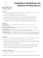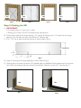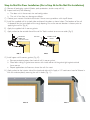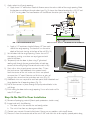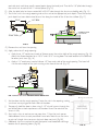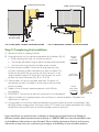
1
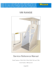
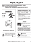
Installation
Guidelines
Patio Doors
Inswing / Outswing / Entry / Sliding Patio Door
900 South 19th Street
West Des Moines, IA 50265
800.935.2000
www.ashworthdoors.com
#5011892 4/2012
Installation Guidelines for
Ashworth Patio Doors
Installer
• Read
instructions completely before attempting installation. Failure to follow these guidelines will forfeit
the Ashworth warranty coverage, written or implied.
• Always provide a copy of these instructions to the homeowner.
• These instructions are consistent with ASTM 2112 “Standard Practice for Installation of Exterior
Windows, Doors and Skylights” into common wall constructions. Contact your architect or
construction professional for installation into other building designs or construction methods.
• Regional codes and environmental conditions may require installation that is different from
these guidelines. It is your responsibility to ensure that local codes and ordinances are followed.
Warning!
Work Safe! Always wear proper eye and hearing protection when installing or adjusting
Ashworth products.
Use Power Tools Properly! To avoid personal injury, always follow manufacturers’ instructions
for safe operation of power tools.
Ladder Safety! Working at elevated levels can be hazardous. Always use ladders and scaffolding
properly. Consult manufacturers’ guidelines for safe use of these types of equipment.
Safety Glazing! Some Ashworth products may not contain safety glazing unless specifically ordered
that way. Use caution – injury could result if glass is broken and fragmented. Building codes require safety
glazing for windows installed in certain areas. Consult your local building code official for guidelines.
Important
• A
shworth reserves the right to change the information contained in these guidelines without notice.
• Maintain a minimum of 1/4" between the door frame and any trim, siding or masonry.
• Use of Ashworth products in barrier EIFS systems (synthetic stucco) is not recommended. To do so
will forfeit all warranties (written or implied), and Ashworth will not be held responsible for any claims
or damages resulting from water infiltration.
• Steel fasteners will corrode when used with ACQ Pressure Treated Lumber. Use corrosion resistant
fasteners (such as stainless steel) when installing windows in or around these types of materials.
• Door nailing flanges and drip caps (integral or applied) do not take the place of window flashing.
All windows and doors must be properly flashed and sealed around the perimeter.
Handling and Storage
• Always carry door units upright. Do not carry flat! Doing so could result in damage to the unit.
• Do not store units outside.
Note: These installation instructions contain two methods of installation: Nail fin and no nail fin installation.
Tools Needed
Materials Needed
• Safety Glasses
• B
acker Rod
– 1/4"-1/2" diameter closed cell foam
• Utility Knife
• Hammer (or Nail Gun)
• Insulation
– Minimally expanding low pressure
polyurethane window and door foam
• Caulk Gun
• S hims
– Made of cedar or synthetic material
• Level • 2-1/2" Drywall Screws – (No Nail Fin Installation)
• Ladder / Scaffolding • R
oofing Nails (Nail Fin Installation)
– 2" Galvanized (16D)
• Square
• S ilicone Sealant
– 100% Silicone
• Tape Measure • Stapler
• F lashing (Nail Fin Installation)
– Self-adhesive flexible flashing that
complies with ASTM-D779
• Screwdriver
Step 1: Inspect Unit
Before Installation:
A) Remove all shipping packaging material (blocks, pads, protectors, stretch wrap).
B) Inspect unit for any damage or defects.
C) Verify the door unit is the correct size and configuration.
D) Contact the nearest Ashworth distributor if there is a problem.
Step 2: Prepare Rough Opening
Note: Disregard steps B, F, G, H and I if No Nail Fin Installation is utilized.
A) Measure and verify the size of the rough opening. The rough opening should be 3/4" larger in width and
1/2" larger in height than the frame size.
B) For doors with clad exterior casings, additional nailer studs may be required around the perimeter of the
rough opening.
C) Verify the rough opening is flat, plumb, level and square. (Fig. 1)
D) Take diagonal measurements to check for square. (Fig. 1)
E) Make sure the bottom sill area of the rough opening is flat and level. Correct rough opening if sloped
towards the interior, out of level or humped. (Fig. 1)
F) Cut the weather-resistant barrier (WRB) in a “Modified I” pattern. (Fig. 2)
G) Fold back the WRB on the sides toward the interior and staple into place. (Fig. 3)
H) From the exterior, cut the top of the WRB as shown to form a flap. (Fig. 4)
I) Temporarily tape this top flap up. (Fig. 4)
int
eXT
fig. 1
int
eXT
fig. 3
fig. 2
fig. 4
Step 3: Flashing the Sill
A) IMPORTANT!
a. Use flashing that is 6" minimum in width.
b. Flashing must meet ASTM-D779 performance requirements.
B) Measure the width of the rough opening. Cut a length of flashing that is 12" wider than the rough
opening. This will allow you to run the flashing 6" up each side.
C) Cut 1-1/2" slits at each end of the flashing as shown below. (Fig. 5)
6" minimum
1-1/2"
6"
1/2"
fig. 5
D) Apply sill flashing to the rough opening as shown below. (Fig. 6)
E) Flashing tape must cover the entire sill. If needed, apply an additional flashing piece over the first one
(start from the exterior and work towards the interior). Maintain a minimum 1" overlap. (Fig. 7)
int
eXT
int
eXT
fig. 6
fig. 7
Step 4a: Nail Fin Door Installation (Go to Step 4b for No Nail Fin Installation)
A) Removeallpackagingmaterial(blocks,pads,protectors,stretchwrap,nailfin).
B) Inspectandverifythefollowing:
a. Thedoorunitisthecorrectsizeandconfiguration.
b. Theunitisfreefromanydamageordefects.
C) ContactyournearestAshworthdistributorifthereareanyproblemswithstepBabove.
D) Installthesuppliednailfintobothsidesandtopofthedoorasshownbelow.Thelocationofthenail
findependsonthejambdepthoftheroughopening.Ensurethecorrectlocationischosenpriorto
applyingthenailfin.(Fig.8)
E) Applythesuppliednailfincornergaskets.
F) Applysealanttotheoutsidefaceofthenailfin.Toolinsealanttoensurenovoids.(Fig.9)
NAIL FIN
DRIP CAP
(MULLED UNITS)
FIG. 8
SILICONE
DESIRED JAMB
DEPTH
FIG. 9
G) Installuppernailfincornergaskets.(Fig.10)
a. Removeprotectivepaperfrombackofnailfincornergasket.
b. Placefoamnailingfingasketovercornerwithinsidecornerofthegaskettightagainstoutside
framecorner.
c. Repeatapplicationatallcornerswherethenailfinsmeet.
H) Applysealanttotheinteriorsideoftheheadandsidenailfin.Applya1/4"continuousbeadofsiliconein
linewithandcompletelycoveringthenailfinholes.(Fig.11)
FIG. 10
FIG. 11
I) Applysealanttosillroughopening:
a. Applythree1/4"continuousbeadsofsiliconeacrosstheentirewidthoftheroughopening.Note
thelocationsaredifferentforeachdoortype.Fig.13showsthesiliconelocationfora4-9/16"and
6-9/16"inswingdoor.Thebeadlocationwillbedifferentforotherjambsizes.(Fig.12&13)
4 14" (4 169 " FRAME)
6 14" (6 169 " FRAME)
SEALANT
FIG. 12: OUTSWING PATIO SILL
1" (4 169 " FRAME)
3" (6 169 " FRAME)
FIG. 13: 4-9/16" & 6-9/16" INSWING PATIO DOOR SILL
b. A
pplya1/4"continuousbeadofsilicone1/2"fromeach
sideoftheroughopening. Thebeadwillruntheentire
depthofthejambstartingatthefaceofthewall.(Fig.14)
J) S etthedoorintotheroughopening.Centertheunitin
theopening,makingsurethereareequalgapsonboth
sidesofthedoor.
K) Temporarilytackthedoorinplaceusing2"galvanized
roofingnailsthroughthepre-punchedholesatbothtop
cornersofthenailingflange.Donotdrivethenailsinfully.
eXT
L) S tartwithashimateachcornernomorethan1"from
thejambcorner. Addadditionalshimsspacedevenly
fromthecenteroftheunitmakesureshimsarespaced
nomorethan16"apart.Notetouseflatshimsorpairsof
triangleshimstoensurethejambdoesnottwist.(Fig.15)
M) A
dditionalshimsarerequiredateachlockpoint,headshootboltand
hingelocationforalloperatingdoors.(Fig.15)
N) N
ailallfourcornersinplacethroughthepre-punchedholesinthe
nailflange.
O)Finishnailingthedoortotheroughopening.Useanailateachnailfin
hole,8"-10"apart.
Step 4b: No Nail Fin Door Installation
FIG. 14
SWINGING
PATIODOOR
FIG. 15
A) R
emoveallpackagingmaterial(blocks,pads,protectors,stretchwrap).
B) Inspectandverifythefollowing:
a. Thedoorunitisthecorrectsizeandconfiguration.
b. Theunitisfreefromanydamageordefects.
C) C
ontactyournearestAshworthdistributorifthereareanyproblemswithstepBabove.
D) Measureinfromtheexteriorsideoftheunit2-5/8"andmarkthisatfourequallyspacedpointsalong
eachsidejambandthreeequallyspacedpointsalongtheheadjamb.Thendrilla1/8"pilotholethrough
theentireunitateachofthe11markedplaces.(Fig.16)
E) Afterthepilotholehasbeencreated,drilla25/64"holethroughthealuminumcladdingonly.(Fig.16)
F) Testfittheunitintheroughopeningandsettheunittotheappropriatejambdepth.Oncethecorrect
jambdepthhasbeendetermined,drawalinealongtheinsideofthesillonthesubfloor.(Fig.17)
1/8" DIA.
2-5/8"
INTERIOR LINE
LOCATION
25/64" DIA.
FIG. 16
FIG. 17
G) Removetheunitfromtheopening.
H) Applysealanttosillroughopening:
a. Applythree1/4"continuousbeadsofsiliconeacrosstheentirewidthoftheroughopening.(Fig.18)
showsthesiliconelocationfora4-9/16"and6-9/16"inswingdoor.Thebeadlocationwillbedifferent
forotherjambsizes.(Fig.18)
b. Applya1/4"continuousbeadofsilicone1/2"fromeachsideoftheroughopening.Thebeadwill
runtheentiredepthofthejambstartingatthefaceofthewall.(Fig.19)
SEALANT
4 12" (4 169 " FRAME)
6 12" (6 169 " FRAME)
3 5/8"
1/2"
INT
eXT
FIG. 18: 4-9/16" & 6-9/16" INSWING PATIO DOOR SILL
FIG. 19
I) S etthedoorintotheroughopening.Centertheunitintheopening,making
surethereareequalgapsonbothsidesofthedoor.
J) Temporarilyholdthedoorinplaceusing2-1/2"drywallscrewsthroughthe
pre-drilledholesatbothtopcornersofthedoorframe.Donotdrivethe
screwsinfully.
K) Startwithashimateachcornernomorethan1"fromthejambcorner.
Addadditionalshimsateachpre-drilledframehole.Notetouseflatshims
orpairsoftriangleshimstoensurethejambdoesnottwist.(Fig.20)
L) Additionalshimsarerequiredateachlockpoint,headshootboltandhinge
locationforalloperatingdoors.(Fig.20)
Bi-hingeshootboltshim
SWINGING
PATIODOOR
FIG. 20
M) Screwallfourcornersinplacethroughthepre-drilledholesintheframe.
N) Finishscrewingthedoortotheroughopening.Applyascrewthroughall11pre-dilledframeholes.
Step 5: Secure Hinge and Verify Operation
A) A
pplythesupplied#12x2-1/4"screwsthrougheachhingesecuringthe
hingesandframetotheroughopening.Additionalshimsarerequired
behindeachhinge.(Fig.21)
B) Verifytheoperationofthedooriscorrect.Bydoingsoyouwillverify
thedoorswingswithoutbindingonanothermemberofthedoorandby
remainingmotionlessthroughouttheoperationwhenleftinstaticposition.
C) Iftheoperationofthedoorisnotcorrect,firstverifytheroughopeningis
plumb,levelandsquare.Second,verifythedoorisshimmedandfastened
properlyasstatedintheseinstructions.Third,verifythehingesareadjusted
totheoptimalposition.
FIG. 21
Step 6: Completing the Sill
Note: Disregard Step A if No Nail Fin Installation is utilized.
A) I MPORTANT!Belowthenailfinatbothbottomcorners,applyagenerousamountofsiliconetoseal
thevoidbetweentheroughopeningandthesill.Ifthegapistoolarge,insertbackermaterialinthevoid
priortosealing.(Fig.22)
B) A
ttachasillsupportblockbeneaththesill.Applyabeadofsealantatthenoseofthesillandsupport
block.(Fig.23)
C) Applysiliconetosealeachendofthesillcavitythatprotrudesfromtheroughopening.(Fig.24&25)
SEALANT LOCATION
SILL SUPPORT
(BY OTHERS)
SEALANT
FIG. 22
FIG. 23: STANDARD DOOR SILL
SEALANT
SEALANT
FIG. 24: OUTSWING SILL
FIG. 25: INSWING SILL
Step 7: Complete Flashing (Nail Fin Installation Only)
A) Cutandapplysideflashing.Sideflashingshouldrunfromthebottomofthesillflashingto4"abovethe
roughopening.(Fig.26)
B) Ifnon-adhesiveflashingisused,makesureallstapleholesaresealedwithsilicone.
C) Cutandapplyheadflashing.Theheadflashingshouldrunslightlypasttheedgeofthesideflashingas
shown.(Fig.27)
D) FlipdownthetopflapoftheWRB.(Fig.28)
E) TapethecutseamsoftheWRB.(Fig.29)
FIG. 26
FIG. 27
FIG. 28
FIG. 29
Step 8: Seal the exterior
A) Aftersidingorwallexterioriscomplete,applybackerrodandsealantbetweenthedoorframeand
sidingmaterialonbothsides.Seefigures30and31fornailfininstallationandfigures32and33forno
nailfininstallation.
B) W
ARNING: Maintainaminimumof1/4"betweenthedoorframeandanytrim,sidingormasonry.
Failuretodosowillforfeitallwarranties(writtenorimplied).Ashworthwillnotbeheldresponsiblefor
anyclaimsordamagesresultinginfailuretofollowtheseinstructions.
INSULATION
SHIM & INSULATION
NO SEALANT
1/4" MIN.
SEALANT &
BACKER ROD
1/4" MIN.
FIG. 30: SIDe JAMB – NAIL FIN
INSTALLATION
FIG. 31: HeAD JAMB – NAIL
FIN INSTALLATION
SHIM & INSULATION
SHIM & INSULATION
1/4" MIN.
SEALANT &
BACKER ROD
1/4" MIN.
FIG. 32: SIDe JAMB – NO NAIL FIN INSTALLATION
FIG. 33: HeAD JAMB – NO NAIL FIN INSTALLATION
Step 9: Completing the Installation
A) R
emovealllabelsorshippingmaterials.
B) Hingeadjustmentmayberequiredtocompletetheinstallation.(Fig.34)
Top hinge
adjusts
a. Whenadjustingthehinge,useahandscrewdriver.
horizontally
b. Usethetopandbottomhingetoadjustthedoorpanelhorizontally.
c. Usethecenterhingetoadjustthedoorpanelvertically.
C) Insulatebetweenthedoorframeandtheroughopeningusing
minimallyexpandingwindowanddoorsprayfoaminsulation.Use
cautiontonotoverfillthegapcausingthejambstobow.Itisnot
Center hinge
recommendedtoapplytrimtotheunituntilthefoamhascured
adjusts vertically
toallowtheexcesstoescape.(Fig.30,31,32&33)
D) Operatedoorunittoensureproperoperation.Thepanelwill
notoperatecorrectlyifthedoorisoutofsquare,over-shimmed
orover-insulated.
Bottom
hinge adjusts
E) ProperlyfinishallInteriorwoodcomponentswithin30days
horizontally
ofinstallation.
FIG. 34
F) IMPORTANT:Donotstainorpaintanyhardwareorvinylcomponents.
G) Applythehandlesetasappropriateperthemanufacturer’srecommendations.Completefinal
adjustmentsasnecessary.
H) Swingingdoorsaretoremainclosedandlockedduringconstructiontopreventsiteconditionsfrom
damagingand/orwarpingpanelsandframes.Allow10-12weeksfromprojectcompletionforbuilding
temperatureandhumiditylevelstostabilizeanddoorpanelstoacclimate.
if you should have any questions from installation to adjustments of the Ashworth by Woodgrain
millwork products please contact Ashworth directly at 1.800.935.2000.Visit www.ashworthdoors.com
to find additional information on your Ashworth Door including maintenance, finishing and warranty
information to help assist you in preserving the integrity and reliability of your Ashworth products.