1
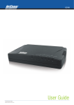
EOC350 Series
Ethernet over Coax Termination System and Terminal Adapter
Version 1.00
Edition 1, 08/2012
Quick Start Guide
User’s Guide
Default Login Details
LAN IP Address
User Name
www.zyxel.com
Password
192.168.1.1
admin
1234
Copyright © 2012 ZyXEL Communications Corporation
IMPORTANT!
READ CAREFULLY BEFORE USE.
KEEP THIS GUIDE FOR FUTURE REFERENCE.
Related Documentation
• Quick
S
tart Guide
The Quick Start Guide shows how to connect the EOC350-TS and EOC350-TA.
Note: It is recommended you use the Web Configurator to configure the EOC350-TS and
EOC350-TA.
2
EOC350 Series User’s Guide
Contents Overview
Contents Overview
Introduction ...............................................................................................................................................9
The Web Configurator .............................................................................................................................15
System Setup ..........................................................................................................................................19
Auto Configuration ..................................................................................................................................21
EP Management .....................................................................................................................................22
Administration .........................................................................................................................................45
System Log .............................................................................................................................................51
System Time ...........................................................................................................................................53
Static MAC ..............................................................................................................................................55
Maintenance ............................................................................................................................................56
Telnet .......................................................................................................................................................61
SNMP ......................................................................................................................................................71
Troubleshooting ......................................................................................................................................73
EOC350 Series User’s Guide
3
Table of Contents
Table of Contents
Contents Overview ..............................................................................................................................3
Table of Contents .................................................................................................................................4
Chapter 1
Introduction...........................................................................................................................................9
1.1 Overview .............................................................................................................................................9
1.1.1 Integrating the EOC350-TS and EOC350-TA with Satellite TV .................................................9
1.1.2 Integrating the EOC350-TS and EOC350-TA with an STB .....................................................10
1.2 EOC350-TS .......................................................................................................................................10
1.2.1 LEDs ........................................................................................................................................ 11
1.2.2 Connections ............................................................................................................................. 11
1.3 EOC350-TA .......................................................................................................................................12
1.3.1 LEDs ........................................................................................................................................12
1.3.2 Connections .............................................................................................................................13
1.4 The RESET Button ............................................................................................................................13
1.5 Ways to Manage the EOC350-TS .....................................................................................................14
Chapter 2
The Web Configurator ........................................................................................................................15
2.1 Overview ...........................................................................................................................................15
2.1.1 Accessing the Web Configurator .............................................................................................15
2.2 Securing the EOC350-TS .................................................................................................................16
2.3 The Web Configurator Layout ...........................................................................................................17
2.3.1 Navigation Panel .....................................................................................................................17
2.3.2 Main Window ...........................................................................................................................18
Chapter 3
System Setup ......................................................................................................................................19
3.1 Overview ...........................................................................................................................................19
3.2 The System Setup Screen ................................................................................................................19
Chapter 4
Auto Configuration .............................................................................................................................21
4.1 Overview ...........................................................................................................................................21
4.2 The Auto Configuration Screen .........................................................................................................21
Chapter 5
EP Management ..................................................................................................................................22
5.1 Overview ...........................................................................................................................................22
4
EOC350 Series User’s Guide
Table of Contents
5.2 The EP Management Screen ............................................................................................................22
5.3 The View Host Screen ......................................................................................................................23
5.4 The View Host Screen ......................................................................................................................24
5.5 Termination System Configuration ....................................................................................................25
5.5.1 The EoC Screen (Privacy Mode) .............................................................................................25
5.5.2 The Port Screen ......................................................................................................................25
5.5.3 The QoS Screen ......................................................................................................................26
5.5.4 The IGMP Screen ....................................................................................................................27
5.5.5 The VLAN Screen ....................................................................................................................28
5.5.6 The Status Screen ...................................................................................................................29
5.6 Testing from the Termination System ................................................................................................29
5.7 Ether EP Default Profile Configuration ..............................................................................................30
5.7.1 The EoC Screen ......................................................................................................................30
5.7.2 The Port Screen ......................................................................................................................31
5.7.3 The QoS Screen ......................................................................................................................32
5.7.4 The IGMP Screen ....................................................................................................................33
5.7.5 The VLAN Screen ....................................................................................................................33
5.7.6 The Filter Screen .....................................................................................................................34
5.8 EP Configuration ...............................................................................................................................35
5.8.1 The EoC Screen ......................................................................................................................35
5.8.2 The Port Screen ......................................................................................................................35
5.8.3 The QoS Screen ......................................................................................................................37
5.8.4 The IGMP Screen ....................................................................................................................37
5.8.5 The VLAN Screen ....................................................................................................................38
5.8.6 The Filter Screen .....................................................................................................................39
5.8.7 The Status Screen ...................................................................................................................39
5.9 Testing from a Termination Adapter ..................................................................................................40
5.9.1 Noise .......................................................................................................................................40
5.9.2 Online Diag ..............................................................................................................................41
5.10 Backup and Restore of Termination Adapter Configuration ............................................................42
5.10.1 Backup Configuration ............................................................................................................42
5.10.2 Restore Configuration ............................................................................................................43
5.11 Adding Offline Termination Adapters ...............................................................................................43
Chapter 6
Administration ....................................................................................................................................45
6.1 Overview ...........................................................................................................................................45
6.2 The Administrator Screen .................................................................................................................45
6.3 The Allowed Source Screen ..............................................................................................................46
6.4 The Telnet Setup Screen ...................................................................................................................47
6.5 The HTTP Setup Screen ...................................................................................................................48
6.6 The SNMP Setup Screen ..................................................................................................................49
6.7 The SNMP Trap Server Screen ........................................................................................................49
EOC350 Series User’s Guide
5
Table of Contents
Chapter 7
System Log .........................................................................................................................................51
7.1 Overview ...........................................................................................................................................51
7.2 The Syslog Setup Screen .................................................................................................................51
7.3 The Syslog View Screen ...................................................................................................................52
Chapter 8
System Time........................................................................................................................................53
8.1 Overview ...........................................................................................................................................53
8.2 The SNTP Setup Screen ...................................................................................................................53
8.3 The View Time Screen ......................................................................................................................54
Chapter 9
Static MAC ...........................................................................................................................................55
9.1 Overview ...........................................................................................................................................55
9.2 The Static MAC Screen .....................................................................................................................55
Chapter 10
Maintenance ........................................................................................................................................56
10.1 Overview .........................................................................................................................................56
10.2 Rebooting the System .....................................................................................................................56
10.3 Restoring Default Settings ..............................................................................................................56
10.4 Uploading Firmware ........................................................................................................................56
10.5 The Activate Firmware Screen ........................................................................................................58
10.6 Backup and Restore ........................................................................................................................59
10.6.1 Backup Configuration ............................................................................................................59
10.6.2 Restore Configuration ............................................................................................................60
Chapter 11
Telnet ...................................................................................................................................................61
11.1 Overview .........................................................................................................................................61
11.2 Config Telnet Server ........................................................................................................................61
11.2.1 Command Format ..................................................................................................................61
11.2.2 Generic Command Sets .........................................................................................................62
Chapter 12
SNMP ...................................................................................................................................................71
12.1 Overview .........................................................................................................................................71
Chapter 13
Troubleshooting..................................................................................................................................73
13.1 Power, Hardware Connections, and LEDs ......................................................................................73
13.2 EOC350-TS Access and Login .......................................................................................................74
6
EOC350 Series User’s Guide
Table of Contents
13.3 Bandwidth and Connectivity ............................................................................................................75
13.4 Resetting the EOC350-TS to Factory Defaults ...............................................................................76
Appendix A Legal Information............................................................................................................79
EOC350 Series User’s Guide
7
Table of Contents
8
EOC350 Series User’s Guide
C HAPT ER
1
Introduction
1.1 Overview
The EOC350-TS is an Ethernet over Coax Termination System. The EOC350-TA is an Ethernet over
Coax Terminal Adapter. One centrally-located EOC350-TS serves many EOC350-TAs distributed in
each unit of a Multiple Dwelling Unit (MDU). The following applications show how they integrate
with the existing TV installation in a single unit of an MDU.
1.1.1 Integrating the EOC350-TS and EOC350-TA with Satellite TV
In this application, the EOC350-TS and EOC350-TA have the following media types.
• Ethernet. The EOC350-TS receives an Internet feed via an IP gateway and encodes Ethernet
frames on to the coaxial cable connected to the OUT socket. The EOC350-TA decodes the
Ethernet frames for Ethernet devices such as the PC.
• Coaxial. The EOC350-TS receives a satellite TV signal over coaxial cable via the IN socket and
mixes this with the encoded Ethernet frames. The combined signal is sent through the coaxial
cable connected to the OUT socket. The EOC350-TA takes the combined signal from its IN
socket, separates the satellite TV signal and sends it to it’s OUT socket for the TV.
Figure 1 Integrating the EOC350-TS and EOC350-TA with Satellite TV
EOC350 Series User’s Guide
9
Chapter 1 Introduction
1.1.2 Integrating the EOC350-TS and EOC350-TA with an STB
In this application, the EOC350-TS and EOC350-TA have the following media types.
• Ethernet. The EOC350-TS receives an Internet feed via an IP gateway and encodes Ethernet
frames on to the coaxial cable connected to the OUT socket. The EOC350-TA decodes the
Ethernet frames for Ethernet devices such as the PC and STB (Set Top Box).
• Coaxial. The EOC350-TS encodes Ethernet frames on to the coaxial cable connected to the OUT
socket. The EOC350-TA decodes the signal from its IN socket for Ethernet devices.
Figure 2 Integrating the EOC350-TS and EOC350-TA with an STB
Note: After power up, the Link/Act LED on the EOC350-TS will light up if at least one End
Point (EP) is detected on the Ethernet over Coax (EoC) network. (An EOC350-TA is
called an EP in the Web Configurator.) A dimmed Link/Act LED shows no EP
attached to the EoC network.
Note: The minimum attenuation between an EOC350-TS and the EOC350-TA is 15dB.
Each EOC350-TA is usually connected to the coaxial cable via a cable tap that
contributes more than 20dB attenuation. If you intend to connect the EOC350-TS
and EOC350-TA directly for test purpose, please add an attenuator that exceeds
15dB to the coaxial cable.
1.2 EOC350-TS
The EOC350-TS is an Ethernet over Coax Termination System. The EOC350-TS combines TV and
Ethernet media on to a coaxial cable for distribution to EOC350-TAs.
10
EOC350 Series User’s Guide
Chapter 1 Introduction
1.2.1 LEDs
The following table describes the EOC350-TS LEDs.
Table 1 EOC350-TS LEDs
LED
DESCRIPTION
DIAG
This LED turns on when you configure the EOC350-TS to check the Ethernet over Coaxial
connection with an EOC350-TA. If the LED is dim then no EOC350-TA has been found in the
Ethernet over Coaxial cable network.
QLTY
This LED shows the Ethernet over Coaxial cable speed. green is high, orange is medium
and red is low. If the LED suddenly becomes red, there may be noise interference. Check
the web configurator for further information.
LINK/ACT
This LED is steady green when there is an Ethernet over Coaxial connection and blinks
when there is traffic.
2
This LED is steady green when there is an Ethernet connection and blinks when there is
traffic. This LED is steady orange when there is a Gigabit Ethernet connection and blinks
when there is traffic.
1
This LED is steady green when there is an Ethernet connection and blinks when there is
traffic. This LED is steady orange when there is a Gigabit Ethernet connection and blinks
when there is traffic.
PWR
This LED is on green when the EOC350-TS is receiving power.
Note: None of the LEDs are on if the EOC350-TS is not receiving power.
1.2.2 Connections
Di
ct
Qu
ali
k/A
Lin
LA
Po
we
r
LA
N1
N2
ty
ag
no
sis
Figure 3 EOC350-TS Connections
OUT
IN
2
PO
WE
12 R
VD
C
L IN
E
ER
POW N
D C -I
ER
POW UT
D C -O
12V
1
RESE
T
12V
Power Switch
Power Out
Power In
EOC350 Series User’s Guide
Reset
Ethernet Ports
OUT
IN
11
Chapter 1 Introduction
The following table describes the connections.
Table 2 EOC350-TS Connections
ITEM
DESCRIPTION
Power Switch
This rocker switch has the following positions:
•
•
POWER DC IN: Push the rocker switch to POWER 12V DC when you want the
EOC350-TS to receive power from a power outlet. The included power adaptor must be
connected from POWER 12V DC-IN to a power outlet.
LINE: Push the rocker switch to LINE when you want the EOC350-TS to receive
power (up to 1 amp) from a coaxial power inserter connected to the IN port. A
48V~90V, 50Hz or 60 Hz AC input from coax is necessary.
Power 12V DC-IN
To receive power from a power outlet, connect the included power adapter from this port
to a power outlet and make sure the rocker switch on the side is set to DC IN.
Power 12V DCOUT
To provide power (up to 1 amp) to a device, such as a PON switch, connect a cable with an
RCA connector-to-DC plug to the device, connect a coaxial power inserter to the IN port,
and push the rocker switch on the side to LINE.
Ethernet Ports
These are Gigabit Ethernet ports that can be used to connect a computer for initial
configuration and then connect to a switch or broadband device with Internet access.
Reset
While EOC350-TS is on, use a pin to press and release this button to restart the EOC350TS. Press and hold for five seconds, then release to restore all EOC350-TS settings to the
factory defaults, including the IP address (default 192.168.1.1).
IN
Connect this port to a satellite TV, cable TV or VHF/UHF antenna to receive analog video
directly. The OUT port on the EOC350-TA can then be connected directly to an analog TV.
OUT
Connect this port to an existing coaxial cable outlet that is in the same coaxial network as
the EOC350-TA in the building.
1.3 EOC350-TA
The EOC350-TA is an Ethernet over Coax Terminal Adapter. The EOC350-TA extracts TV and
Ethernet media from a coaxial distribution cable for consumption by end-user devices such as PCs
and TVs.
1.3.1 LEDs
The following table describes the EOC350-TA LEDs.
Table 3 EOC350-TA LEDs
LED
DESCRIPTION
QLTY
This LED shows the Ethernet over Coaxial cable speed. Green is high, orange is medium
and red is low.
PWR
This LED is on when the power is on.
Note: None of the LEDs are on if the EOC350-TA is not receiving power.
12
EOC350 Series User’s Guide
Chapter 1 Introduction
1.3.2 Connections
Figure 4 EOC350-TA Connections
PWR
12V
C IN
D
1
2
/Ac
Link
QLT
t
Y
OUT
IN
OUT
IN
Power In
Ethernet Ports
The following table describes the connections.
Table 4 EOC350-TA Connections
ITEM
DESCRIPTION
IN
Connect this port to an existing coaxial cable outlet in the room that is in the same coaxial
network as the EOC350-TS in the building.
OUT
Connect this port to an analog television directly if the EOC350-TS IN port is connected to
a satellite TV, cable TV or VHF/UHF antenna.
Ethernet Ports
These are Fast Ethernet ports that can be used to connect to a set top box (STB) that then
connects to an analog television (or directly to a smart TV with an Ethernet port). The LED
is steady green when there is an Ethernet connection and blinks when there is traffic.
12V DC-IN
Connect the included power adapter to a power outlet.
1.4 The RESET Button
If you forget your password or cannot access the web configurator, you will need to use the RESET
button at the back of the device to reload thefactory-default configuration file. This means that you
will lose all configurations that you had previously and the passwords will be reset to the defaults.
To set the device back to the factory default settings, press the RESET button for 5 seconds.
EOC350 Series User’s Guide
13
Chapter 1 Introduction
1.5 Ways to Manage the EOC350-TS
Use any of the following methods to manage the EOC350-TS.
• Web Configurator. This is recommended for everyday management of the EOC350-TS using a
(supported) web browser.
• Command Line Interface. Line commands offer an alternative to the web configurator and in
some cases are necessary to configure advanced features. See Chapter 11 Telnet.
• SNMP. The EOC350-TS can be monitored by an SNMP manager. See Chapter 12 SNMP.
14
EOC350 Series User’s Guide
C HAPT ER
2
The Web Configurator
2.1 Overview
The web configurator is an HTML-based management interface that allows easy device setup and
management via Internet browser. Use Internet Explorer 6.0 and later versions, Mozilla Firefox 3
and later versions, or Safari 2.0 and later versions. The recommended screen resolution is 1024 by
768 pixels.
2.1.1 Accessing the Web Configurator
1
Make sure your EOC350-TS hardware is properly connected (refer to the Quick Start Guide).
2
Launch your web browser.
3
Type 192.168.1.1 as the URL.
4
A password screen displays. Type “admin” as the default Username and “1234” as the default
password to access the device’s Web Configurator. Click Login. If you have changed the password,
enter your password and click Login.
Figure 5 Password Screen
Note: For security reasons, the EOC350-TS automatically logs you out if you do not use
the web configurator for five minutes (default). If this happens, log in again.
The System Info screen appears after a successful login.
EOC350 Series User’s Guide
15
Chapter 2 The Web Configurator
Figure 6 System Info
The following table describes the items in this screen.
Table 5 System Info
LABEL
DESCRIPTION
Model
This shows the model number of the device.
Hardware
This shows the hardware version of the device.
System MAC
Address
This shows the MAC address used over the Ethernet connections.
EoC MAC
Address
This shows the MAC address used over the Coax connections.
Bootcode
This shows the version of the program code that loads the system firmware.
System
Firmware
This shows the version of the system firmware.
Working EoC
Driver
This shows the version of the Ethernet over Coax device driver.
Back
Click Back to return to the previous screen.
2.2 Securing the EOC350-TS
Do the following things regularly to make the EOC350-TS more secure and to manage the EOC350TS more effectively.
• Change the password. Use a password that’s not easy to guess and that consists of different
types of characters, such as numbers and letters.
• Write down the password and put it in a safe place.
• Back up the configuration (and make sure you know how to restore it). Restoring an earlier
working configuration may be useful if the device becomes unstable or even crashes. If you
forget your password, you will have to reset the EOC350-TS to its factory default settings. If you
backed up an earlier configuration file, you would not have to totally re-configure the EOC350TS. You could simply restore your last configuration.
16
EOC350 Series User’s Guide
Chapter 2 The Web Configurator
2.3 The Web Configurator Layout
Click Status at the top of the navigation panel (B) to show the following screen.
Figure 7 Web Configurator Layout
A
B
The screen is divided into these parts:
• A - navigation panel
• B - main window
2.3.1 Navigation Panel
Use the menu items on the navigation panel to open screens to configure EOC350-TS features.
EOC350 Series User’s Guide
17
Chapter 2 The Web Configurator
The following table describes each menu item.
Table 6 Navigation Panel Summary
MENU/SUB-MENU
FUNCTION
System Info
Use this menu to see the MAC addresses and hardware and software
versions of the device.
System Setup
Use this menu to configure the IP and DHCP Snooping parameters of the
Ethernet interface facing the Internet Service Provider (ISP).
Auto Configuration
Use this menu to setup automatic retrieval and distribution of (*.shc and
*.ep) configuration files from a TFTP server.
EP Management
Use this menu to view and configure the termination system and
termination adapters, (EPs) and test connectivity between them. An EP is
an EOC350-TA.
Administration
Use this menu to configure access to the management interface.
Administrator
Use this sub-menu to configure user names and passwords allowed to log
in to the management interface.
Allowed Source
Use this sub-menu to configure which computers are allowed access to
the management interface.
Telnet Setup
Use this sub-menu to enable and configure the telnet server.
HTTP Setup
Use this sub-menu to enable and configure the HTTP server.
SNMP Setup
Use this sub-menu to enable and configure the SNMP agent.
SNMP Trap Server
Use this sub-menu to configure where SNMP agent sends SNMP traps.
System Log
Use this menu to configure syslog and view system messages.
Syslog Setup
Use this sub-menu to configure when and where syslog messages are
sent.
View Log
Use this sub-menu to see all messages generated by the system.
System Time
Use this menu to configure and see the system time.
SNTP Setup
Use this sub-menu to configure when and where the time is updated from.
View Time
Use this sub-menu to see the current system time.
Static MAC
Use this menu to configure which MAC addresses are forwarded through
the Ethernet interfaces.
Reboot System
Use this menu to restart the system.
Default Setting
Use this menu to reset the system to factory defaults.
Upload Firmware
Use this menu to put new firmware in the upload area.
Activate Firmware
Use this menu to copy new firmware from the upload area to the working
area and restart with it.
System Firmware
Backup/Restore
Use this sub-menu to copy new firmware from the upload area to the
working area and restart with it.
Use this menu to download and upload configuration files.
Backup Master
Use this sub-menu to download a configuration file.
Restore Master
Use this sub-menu to upload a configuration file.
2.3.2 Main Window
The main window displays information and configuration fields. It is discussed in the rest of this
document. After login, the main window shows the System Info screen.
18
EOC350 Series User’s Guide
C HAPT ER
3
System Setup
3.1 Overview
This chapter describes how to configure the IP and DHCP Snooping parameters of the Ethernet
interface facing the Internet Service Provider (ISP).
3.2 The System Setup Screen
Use this screen to configure the IP and DHCP Snooping parameters. Click System Setup to show
the following screen.
Figure 8 System Setup
The following table describes the items in this screen.
Table 7 System Setup
LABEL
DESCRIPTION
IP Address
Assignment
Select Static to enable manual IP configuration or Dynamic (DHCP) to enable the EOC350TS to get its IP configuration via the Dynamic Host Configuration Protocol (DHCP).
IP Address
Enter the IP address you want to assign to your EOC350-TS in dotted decimal notation, for
example, 192.168.1.1 (factory default).
Subnet Mask
Type the subnet mask of your network in dotted decimal notation, for example
255.255.255.0 (factory default). Your EOC350-TS automatically computes the subnet mask
based on the IP address you enter, so do not change this field unless you are instructed to do
so.
Default
Gateway
Enter the IP address of the default gateway in dotted decimal notation, for example
192.168.1.254.
EOC350 Series User’s Guide
19
Chapter 3 System Setup
Table 7 System Setup (continued)
20
LABEL
DESCRIPTION
Primary DNS
Server
Enter the IP address of the first DNS server the EOC350-TS checks to resolve IP addresses.
Secondary
DNS Server
Enter the IP address of the second DNS server the EOC350-TS checks to resolve IP
addresses.
DHCP Option
82 and IP
Source Guard
Select Disable to pass DHCP traffic without modification. Select DHCP Option 82 Only to
add information about the source of DHCP requests to DHCP request packets and strip this
information from replies. Select DHCP Option 82 and IP Source Guard to add source
information and validate IP/MAC bindings granted by DHCP servers.
Apply
Click Apply to save your settings.
EOC350 Series User’s Guide
C HAPT ER
4
Auto Configuration
4.1 Overview
This chapter describes how to automatically distribute configuration files.
4.2 The Auto Configuration Screen
Use this screen to setup automatic retrieval and distribution of (*.shc and *.ep) configuration files
from a TFTP server. Click Auto Configuration to show the following screen.
Figure 9 Auto Configuration
The following table describes the items in this screen.
Table 8 Auto Configuration
LABEL
DESCRIPTION
Auto
Configuration
by TFTP
Click Enable to make the termination system automatically get configuration via TFTP and
distribute this configuration to termination adapters.
TFTP Server
Name
Type the address of the TFTP server.
Directory Path
Type the source directory on the TFTP server in which the configuration files are stored.
Auto Upgrade
EP EoC Driver
Click Enable to make the termination system automatically upgrade the termination
adapter’s Ethernet over Coax (EoC) driver.
Apply
Click Apply to save your settings.
EOC350 Series User’s Guide
21
C HAPT ER
5
EP Management
5.1 Overview
This chapter describes how to view and configure the EOC350-TS (see Figure 3 on page 11) and the
EOC350-TAs (see Figure 4 on page 13) connected to it, and test connectivity between them.
Note: The EOC350-TA is an End Point (EP).
5.2 The EP Management Screen
Use this screen to view, configure and test the termination system and termination adapters. Click
EP Management to show the following screen.
Figure 10 EP Management
A
B
C
The screen is divided into these regions:
• A - local termination system device configuration
• B - default profile configuration for termination adapters
• C - termination adapter configuration
EOC350 Series User’s Guide
22
Chapter 5 EP Management
The following table describes the items in this screen.
Table 9 EP Management
LABEL
DESCRIPTION
Master
This shows the version of the termination system’s EoC driver in the upload area of the
termination system.
EP
This shows the version of the termination adapter’s EoC driver in the upload area of the
termination system.
On-line EP
This shows the number of termination adapters that are online.
Off-line EP
This shows the number of termination adapters that are offline.
Refresh
Click this to refresh this screen.
View Host
Click this to show which hosts are connected to termination adapters.
Igmp Group
Click this to view IGMP groups and their host members.
No
This shows the index of the row.
Sel
This shows which termination adapters are selected for manual upgrade or reconfiguration.
Click Sel to select all termination adapters.
Link
This shows which the current link status of each device.
•
•
•
•
Green: The device is online. The termination system device is always online unless its
EoC driver is broken.
Yellow: The termination adapter is being initialized by the termination system.
Red: The termination adapter is active but can’t be configured by termination system.
Gray: The termination adapter is offline.
PE (Up/Dn)
This shows the Payload Encoding (PE) in Mbps for the upstream and downstream directions
between each termination adapter and the termination system. Click this to refresh the
column.
MAC
This shows the MAC address used over Coax.
Model
This shows the current queried model number.
EoC Driver
This shows the current queried working (running) EoC driver version.
Note
This shows a user definable note for the device.
Ether
Click Config to configure EoC and Ethernet properties of a device. These properties are
stored in the termination system’s nonvolatile memory and downloaded to termination
adapters when they power up.
Test
Click Test to run the built-in diagnostic functions.
Mtn
Click Backup or Restore to download or upload a termination adapter’s configuration file.
Upgrade EoC
Driver
Click this to upgrade the EoC drivers of the selected termination adapters with new driver in
the termination system’s upload area.
ReConfig
Click this to reload the EoC configuration of the selected termination adapters from the
termination system.
Add EP
Click this to add an offline termination adapter profile. This is useful for provisioning
termination adapters before they go online.
Del EP
Click this to add an offline termination adapter profile. This saves memory on the
termination system.
5.3 The View Host Screen
Use this screen to view which hosts are connected to termination adapters. Click EP Management
> View Host to show the following screen.
EOC350 Series User’s Guide
23
Chapter 5 EP Management
Figure 11 EP Management > View Host
The following table describes the items in this screen.
Table 10 EP Management > View Host
LABEL
DESCRIPTION
EP
This is the MAC address of the termination adapter.
Host
This is the MAC address of the host.
5.4 The View Host Screen
Use this screen to view IGMP groups and their host members. Click EP Management > Igmp
Group to show the following screen.
Figure 12 EP Management > Igmp Group
The following table describes the items in this screen.
Table 11 EP Management > Igmp Group
24
LABEL
DESCRIPTION
Group
This is the IP address of the multicast group.
Host
This is the IP address of the host member of the multicast group.
EOC350 Series User’s Guide
Chapter 5 EP Management
5.5 Termination System Configuration
This section describes the configuration screens for the termination system (Local Device).
5.5.1 The EoC Screen (Privacy Mode)
Use this screen to restrict which termination adapters can send and receive data through the
termination system. Click EP Management > Ether > Config > EoC on the local termination
system device to show the following screen.
Figure 13 EP Management > Ether > Config > EoC (termination system)
The following table describes the items in this screen.
Table 12 EP Management > Ether > Config > EoC (termination system)
LABEL
DESCRIPTION
Note
Type a note here.
Privacy Mode
Select On to require termination adapters to have the same privacy key as the termination
system to send packets through it. Select Off to allow termination adapters to send packets
through the termination system without using a privacy key.
Privacy Key
Type a 16-bit key here. The factory default key is 0, which disables privacy mode.
Apply
Click Apply to save your settings.
Back
Click Back to return to the previous screen.
5.5.2 The Port Screen
Use this screen to throttle the bandwidth of the termination system’s interfaces. Click EP
Management > Ether > Config > Port on the local termination system device to show the
following screen.
EOC350 Series User’s Guide
25
Chapter 5 EP Management
Figure 14 EP Management > Ether > Config > Port (termination system)
The following table describes the items in this screen.
Table 13 EP Management > Ether > Config > Port (termination system)
LABEL
DESCRIPTION
Port
This shows the port name for this row.
Speed/Duplex
Select the speed and the duplex mode of the Ethernet connection on this port. Choices are
Auto, 10M/Full, 10M/Half, 100M/Full, 100M/Half. Selecting Auto (auto-negotiation)
allows the port to negotiate with a peer port automatically to obtain the connection speed
and duplex mode that both ends support. If the peer port does not support auto negotiation
or turns off this feature, the EOC350-TS determines the connection speed by detecting the
signal on the cable and using half duplex mode.
Flow Ctrl
A concentration of traffic on a port decreases port bandwidth and overflows buffer memory
causing frame losses. Select On to enable flow control and regulate transmission of frames
to match the bandwidth of the receiving port.
Enable UpRate
Limit
Select Enable to throttle the upstream bandwidth through this port.
UpRate
(*64Kbps)
Type a bandwidth value in 64Kbps increments. If this exceeds 1536 (100Mbps) on an
termination adapter LAN port or 3125 (200Mbps) on an FoC port, there will be no bandwidth
throttling.
Enable
DownRate
Limit
Select Enable to throttle the downstream bandwidth through this port.
DownRate
(*64Kbps)
Type a bandwidth value in 64Kbps increments. If this exceeds 1536 (100Mbps) on a
termination adapter LAN port or 3125 (200Mbps) on an FoC port, there will be no bandwidth
throttling.
Apply
Click Apply to save your settings.
Back
Click Back to return to the previous screen.
5.5.3 The QoS Screen
Use this screen to prioritize traffic flow through the termination system’s interfaces. Click EP
Management > Ether > Config > QoS on the local termination system device to show the
following screen.
26
EOC350 Series User’s Guide
Chapter 5 EP Management
Figure 15
Management > Ether > Config > QoS (termination system)
The following table describes the items in this screen.
Table 14 Management > Ether > Config > QoS (termination system)
LABEL
DESCRIPTION
Priority base
on
Select 802.1p to configure the IEEE 802.1p prioritization scheme for incoming frames.
Select IP TOS/TC or DSCP to configure the IP prioritization scheme.
Queue
Scheduling
Select Strict Priority to forward packets in the higher priority queues first (Q0 has the
lowest priority). Packets in the lower priority queues will be forwarded after the higher
priority queues are empty.
Select Weight fair Queue to forward 8 packets from Q3, then 4 packets from Q2, then 2
packets from Q1, and then 1 packet from Q0.
Select Mix mode to use strict priority to forward packets from Q3 first, and weighted fair
queuing to forward packets from Q2, Q1, and Q0.
Port
Type a TCP/UDP port number to prioritize traffic for important applications.
Queue
Select a queue for this port.
Apply
Click Apply to save your settings.
Back
Click Back to return to the previous screen.
5.5.4 The IGMP Screen
Use this screen to enable IGMP v1/2 fast leave on the termination system’s interfaces. Click EP
Management > Ether > Config > IGMP on the local termination system device to show the
following screen.
Figure 16 EP Management > Ether > Config > IGMP (termination system)
EOC350 Series User’s Guide
27
Chapter 5 EP Management
The following table describes the items in this screen.
Table 15 EP Management > Ether > Config > IGMP (termination system)
LABEL
DESCRIPTION
IGMP Snooping
Select Enable to enable IGMP v1/2 fast leave. Select Disable if only IGMP v3 is
implemented on the network.
Apply
Click Apply to save your settings.
Back
Click Back to return to the previous screen.
5.5.5 The VLAN Screen
Use this screen to configure VLAN tagging on the termination system’s interfaces. Click EP
Management > Ether > Config > VLAN on the local termination system device and then select
Enable from Tag VLAN to show the following screen.
Figure 17 EP Management > Ether > Config > VLAN (termination system)
The following table describes the items in this screen.
Table 16 EP Management > Ether > Config > VLAN (termination system)
LABEL
DESCRIPTION
Cascade Mode
28
Tag V LAN
Select Enable to enable VLAN tagging.
Port
This shows the port name for this row.
Priority
Select the 802.1Q priority applied to incoming frames.
VID
Select the 802.1Q VLAN ID applied to incoming frames.
In Rule
Select Accept All to forward all incoming frames regardless of VID. Select VID Matched to
forward only the incoming frames that match the port VID.
Out Rule
Select Tag to add an 802.1Q tag to egress frames. Select Untag to remove the 802.1Q tag
from egress frames. Select Bypass to leave the tag of the frame alone.
Apply
Click Apply to save your settings.
Back
Click Back to return to the previous screen.
EOC350 Series User’s Guide
Chapter 5 EP Management
5.5.6 The Status Screen
Use this screen to see the status of the termination system’s interfaces. Click EP Management >
Ether > Config > Status on the local termination system device to show the following screen.
Figure 18 EP Management > Ether > Config > Status (termination system)
The following table describes the items in this screen.
Table 17 EP Management > Ether > Config > Status (termination system)
LABEL
DESCRIPTION
Status
Link
This shows whether the port is up or down.
Speed/Duplex
This shows the speed and the duplex mode of the Ethernet connection on this port.
Flow Control
This shows whether flow control is enabled on this port.
Statistics
CLEAR
Click this to clear the port traffic statistics.
RxPkt
This shows how many packets have been received by this port.
RxByte
This shows how many bytes have been received by this port.
TxPkt
This shows how many packets have been sent from this port.
TxByte
This shows how many bytes have been sent from this port.
Collision
This shows how many Ethernet collisions have been detected on this port.
Error
This shows how many errors have been detected on this port.
Refresh
Click this to refresh this screen.
Back
Click Back to return to the previous screen.
5.6 Testing from the Termination System
Follow these steps to measure the noise spectrum at the termination system’s coax interface.
1
Click EP Management > Test in the termination system region of the screen.
EOC350 Series User’s Guide
29
Chapter 5 EP Management
Figure 19
2
Management > Test (termination system)
Click Noise. The EOC350-TS measures the noise spectrum and shows the following screen.
Figure 20
Management > Test (termination system)
5.7 Ether EP Default Profile Configuration
This section describes the screens that allow the default configuration to be setup for termination
adapters.
5.7.1 The EoC Screen
Use this screen to restrict how many hosts can send and receive data through the termination
adapter. Click EP Management > Ether > Config on the default profile to show the following
screen.
30
EOC350 Series User’s Guide
Chapter 5 EP Management
Figure 21 EP Management > Ether > Config (profile)
The following table describes the items in this screen.
Table 18 EP Management > Ether > Config (profile)
LABEL
DESCRIPTION
Note
Type a note here.
Host Limit
Type the maximum hosts allowed to connect to the termination adapter. Service is disabled if
this is 0.
Apply
Click Apply to save your settings.
Back
Click Back to return to the previous screen.
5.7.2 The Port Screen
Use this screen to throttle the bandwidth of the termination adapter’s interfaces. Click EP
Management > Ether > Config > Port on the default profile to show the following screen.
Figure 22 EP Management > Ether > Config > Port (profile)
The following table describes the items in this screen.
Table 19 EP Management > Ether > Config > Port (profile)
LABEL
DESCRIPTION
Port
This shows the port name for this row.
Service
Select On to enable this port or Off to disable it.
EOC350 Series User’s Guide
31
Chapter 5 EP Management
Table 19 EP Management > Ether > Config > Port (profile) (continued)
LABEL
DESCRIPTION
Speed/Duplex
Select the speed and the duplex mode of the Ethernet connection on this port. Choices are
Auto, 10M/Full, 10M/Half, 100M/Full, 100M/Half. Selecting Auto (auto-negotiation)
allows the port to negotiate with a peer port automatically to obtain the connection speed
and duplex mode that both ends support. If the peer port does not support auto negotiation
or turns off this feature, the EOC350-TA determines the connection speed by detecting the
signal on the cable and using half duplex mode.
Flow Ctrl
A concentration of traffic on a port decreases port bandwidth and overflows buffer memory
causing frame losses. Select On to enable flow control and regulate transmission of frames
to match the bandwidth of the receiving port.
Enable UpRate
Limit
Select Enable to throttle the upstream bandwidth through this port.
UpRate
(*64Kbps)
Type a bandwidth value in 64Kbps increments. If this exceeds 1536 (100Mbps) on a
termination adapter LAN port or 3125 (200Mbps) on an FoC port, there will be no bandwidth
throttling.
Enable
DownRate
Limit
Select Enable to throttle the downstream bandwidth through this port.
DownRate
(*64Kbps)
Type a bandwidth value in 64Kbps increments. If this exceeds 1536 (100Mbps) on a
termination adapter LAN port or 3125 (200Mbps) on an FoC port, there will be no bandwidth
throttling.
Apply
Click Apply to save your settings.
Back
Click Back to return to the previous screen.
5.7.3 The QoS Screen
Use this screen to prioritize traffic flow through the termination adapter’s interfaces. Click EP
Management > Ether > Config > QoS on the default profile to show the following screen.
Figure 23 EP Management > Ether > Config > QoS (profile)
32
EOC350 Series User’s Guide
Chapter 5 EP Management
The following table describes the items in this screen.
Table 20 EP Management > Ether > Config > QoS (profile)
LABEL
DESCRIPTION
Priority base
on
Select 802.1p to configure the IEEE 802.1p prioritization scheme for incoming frames.
Select IP TOS/TC or DSCP to configure the IP prioritization scheme.
Queue
Scheduling
Select Strict Priority to forward packets in the higher priority queues first (Q0 has the
lowest priority). Packets in the lower priority queues will be forwarded after the higher
priority queues are empty.
Select Weight fair Queue to forward 8 packets from Q3, then 4 packets from Q2, then 2
packets from Q1, and then 1 packet from Q0.
Select Mix mode to use strict priority to forward packets from Q3 first, and weighted fair
queuing to forward packets from Q2, Q1, and Q0.
Port
Type a TCP/UDP port number to prioritize traffic for important applications.
Queue
Select a queue for this port.
Apply
Click Apply to save your settings.
Back
Click Back to return to the previous screen.
5.7.4 The IGMP Screen
Use this screen to enable IGMP v1/2 fast leave on the termination adapter’s interfaces. Click EP
Management > Ether > Config > IGMP on the default profile to show the following screen.
Figure 24 EP Management > Ether > Config > IGMP (profile)
The following table describes the items in this screen.
Table 21 EP Management > Ether > Config > IGMP (profile)
LABEL
DESCRIPTION
IGMP Snooping
Select Enable to enable IGMP v1/2 fast leave. Select Disable if only IGMP v3 is
implemented on the network.
Apply
Click Apply to save your settings.
Back
Click Back to return to the previous screen.
5.7.5 The VLAN Screen
Use this screen to configure VLAN tagging on the termination adapter’s interfaces. Click EP
Management > Ether > Config > VLAN on the default profile and then select Enable from Tag
VLAN to show the following screen.
EOC350 Series User’s Guide
33
Chapter 5 EP Management
Figure 25
EP Management > Ether > Config > VLAN (profile)
The following table describes the items in this screen.
Table 22
EP Management > Ether > Config > VLAN (profile)
LABEL
DESCRIPTION
Tag V LAN
Select Enable to enable VLAN tagging.
Port
This shows the port name for this row.
Priority
Select the 802.1Q priority applied to incoming frames.
VID
Select the 802.1Q VLAN ID applied to incoming frames.
In Rule
Select Accept All to forward all incoming frames regardless of VID. Select VID Matched to
forward only the incoming frames that match the port VID.
Out Rule
Select Tag to add an 802.1Q tag to egress frames. Select Untag to remove the 802.1Q tag
from egress frames. Select Bypass to leave the tag of the frame alone.
Apply
Click Apply to save your settings.
Back
Click Back to return to the previous screen.
5.7.6 The Filter Screen
Use this screen to configure the hosts that are allowed to send and receive traffic via the
termination adapter’s interfaces. Click EP Management > Ether > Config > Filter on the default
profile to show the following screen.
Figure 26 EP Management > Ether > Config > Filter (profile)
34
EOC350 Series User’s Guide
Chapter 5 EP Management
The following table describes the items in this screen.
Table 23 EP Management > Ether > Config > Filter (profile)
LABEL
DESCRIPTION
Allowed Host
MAC
This shows the hosts that are allowed to send and receive traffic via the EP. If no hosts are
listed then all hosts are allowed, otherwise only the listed hosts are allowed.
Add
Type a MAC address and then click Add to add a host to the Allowed Host MAC list.
Del
Click Del to delete a host from the Allowed Host MAC list.
Back
Click Back to return to the main EP Management screen.
5.8 EP Configuration
This section describes the screens that configure the default profile for termination adapters.
5.8.1 The EoC Screen
Use this screen to restrict how many hosts can send and receive data through the termination
adapter. Click EP Management > Ether > Config on the termination adapter to show the
following screen.
Figure 27 EP Management > Ether > Config (termination adapter)
The following table describes the items in this screen.
Table 24 EP Management > Ether > Config (termination adapter)
LABEL
DESCRIPTION
Note
Type a note here.
Host Limit
Type the maximum hosts allowed to connect to the termination adapter. Service is disabled if
this is 0.
Apply
Click Apply to save your settings.
Back
Click Back to return to the main EP Management screen.
5.8.2 The Port Screen
Use this screen to throttle the bandwidth of the termination adapter’s interfaces. Click EP
Management > Ether > Config > Port on the termination adapter to show the following screen.
EOC350 Series User’s Guide
35
Chapter 5 EP Management
Figure 28 EP Management > Ether > Config > Port (termination adapter)
The following table describes the items in this screen.
Table 25 EP Management > Ether > Config > Port (termination adapter)
36
LABEL
DESCRIPTION
Port
This shows the port name for this row.
Service
Select On to enable this port or Off to disable it.
Speed/Duplex
Select the speed and the duplex mode of the Ethernet connection on this port. Choices are
Auto, 10M/Full, 10M/Half, 100M/Full, 100M/Half. Selecting Auto (auto-negotiation)
allows the port to negotiate with a peer port automatically to obtain the connection speed
and duplex mode that both ends support. If the peer port does not support auto negotiation
or turns off this feature, the EOC350-TA determines the connection speed by detecting the
signal on the cable and using half duplex mode.
Flow Ctrl
A concentration of traffic on a port decreases port bandwidth and overflows buffer memory
causing frame losses. Select On to enable flow control and regulate transmission of frames
to match the bandwidth of the receiving port.
Enable UpRate
Limit
Select Enable to throttle the upstream bandwidth through this port.
UpRate
(*64Kbps)
Type a bandwidth value in 64Kbps increments. If this exceeds 1536 (100Mbps) on a
termination adapter LAN port or 3125 (200Mbps) on an FoC port, there will be no bandwidth
throttling.
Enable
DownRate
Limit
Select Enable to throttle the downstream bandwidth through this port.
DownRate
(*64Kbps)
Type a bandwidth value in 64Kbps increments. If this exceeds 1536 (100Mbps) on a
termination adapter LAN port or 3125 (200Mbps) on an FoC port, there will be no bandwidth
throttling.
Apply
Click Apply to save your settings.
Back
Click Back to return to the main EP Management screen.
EOC350 Series User’s Guide
Chapter 5 EP Management
5.8.3 The QoS Screen
Use this screen to prioritize traffic flow through the termination adapter’s interfaces. Click EP
Management > Ether > Config > QoS on the termination adapter to show the following screen.
Figure 29 EP Management > Ether > Config > QoS (termination adapter)
The following table describes the items in this screen.
Table 26 EP Management > Ether > Config > QoS (termination adapter)
LABEL
DESCRIPTION
Priority base
on
Select 802.1p to configure the IEEE 802.1p prioritization scheme for incoming frames.
Select IP TOS/TC or DSCP to configure the IP prioritization scheme.
Queue
Scheduling
Select Strict Priority to forward packets in the higher priority queues first (Q0 has the
lowest priority). Packets in the lower priority queues will be forwarded after the higher
priority queues are empty.
Select Weight fair Queue to forward 8 packets from Q3, then 4 packets from Q2, then 2
packets from Q1, and then 1 packet from Q0.
Select Mix mode to use strict priority to forward packets from Q3 first, and weighted fair
queuing to forward packets from Q2, Q1, and Q0.
Port
Type a TCP/UDP port number to prioritize traffic for important applications.
Queue
Select a queue for this port.
Apply
Click Apply to save your settings.
Back
Click Back to return to the main EP Management screen.
5.8.4 The IGMP Screen
Use this screen to enable IGMP v1/2 fast leave on the termination adapter’s interfaces. Click EP
Management > Ether > Config > IGMP on the termination adapter to show the following screen.
EOC350 Series User’s Guide
37
Chapter 5 EP Management
Figure 30 EP Management > Ether > Config > IGMP (termination adapter)
The following table describes the items in this screen.
Table 27 EP Management > Ether > Config > IGMP (termination adapter)
LABEL
DESCRIPTION
IGMP Snooping
Select Enable to enable IGMP v1/2 fast leave. Select Disable if only IGMP v3 is
implemented on the network.
Apply
Click Apply to save your settings.
Back
Click Back to return to the main EP Management screen.
5.8.5 The VLAN Screen
Use this screen to configure VLAN tagging on the termination adapter’s interfaces. Click EP
Management > Ether > Config > VLAN on the termination adapter to show the following screen.
Figure 31 EP Management > Ether > Config > VLAN (termination adapter)
The following table describes the items in this screen.
Table 28 EP Management > Ether > Config > VLAN (termination adapter)
38
LABEL
DESCRIPTION
Tag V LAN
Select Enable to enable VLAN tagging.
Port
This shows the port name for this row.
Priority
Select the 802.1Q priority applied to incoming frames.
VID
Select the 802.1Q VLAN ID applied to incoming frames.
In Rule
Select Accept All to forward all incoming frames regardless of VID. Select VID Matched to
forward only the incoming frames that match the port VID.
Out Rule
Select Tag to add an 802.1Q tag to egress frames. Select Untag to remove the 802.1Q tag
from egress frames. Select Bypass to leave the tag of the frame alone.
EOC350 Series User’s Guide
Chapter 5 EP Management
Table 28 EP Management > Ether > Config > VLAN (termination adapter) (continued)
LABEL
DESCRIPTION
Apply
Click Apply to save your settings.
Back
Click Back to return to the main EP Management screen.
5.8.6 The Filter Screen
Use this screen to configure the hosts that are allowed to send and receive traffic via the
termination adapter’s interfaces. Click EP Management > Ether > Config > Filter on the
termination adapter to show the following screen.
Figure 32 EP Management > Ether > Config > Filter (termination adapter)
The following table describes the items in this screen.
Table 29 EP Management > Ether > Config > Filter (termination adapter)
LABEL
DESCRIPTION
Allowed Host
MAC
This shows the hosts that are allowed to send and receive traffic via the termination adapter.
If no hosts are listed then all hosts are allowed, otherwise only the listed hosts are allowed.
Add
Type a MAC address and then click Add to add a host to the Allowed Host MAC list.
Del
Click Del to delete a host from the Allowed Host MAC list.
Back
Click Back to return to the main EP Management screen.
5.8.7 The Status Screen
Use this screen to see the status of the termination system’s interfaces. Click EP Management >
Ether > Config > Status on the termination adapter to show the following screen.
EOC350 Series User’s Guide
39
Chapter 5 EP Management
Figure 33
Management > Ether > Config > Status (termination adapter)
The following table describes the items in this screen.
Table 30
Management > Ether > Config > Status (termination adapter)
LABEL
DESCRIPTION
Status
Link
This shows whether the port is up or down.
Speed/Duplex
This shows the speed and the duplex mode of the Ethernet connection on this port.
Flow Control
This shows whether flow control is enabled on this port.
Statistics
CLEAR
Click this to clear the port traffic statistics.
RxPkt
This shows how many packets have been received by this port.
RxByte
This shows how many bytes have been received by this port.
TxPkt
This shows how many packets have been sent from this port.
TxByte
This shows how many bytes have been sent from this port.
Collision
This shows how many Ethernet collisions have been detected on this port.
Error
This shows how many errors have been detected on this port.
Refresh
Click this to refresh this screen.
Back
Click Back to return to the main EP Management screen.
5.9 Testing from a Termination Adapter
This section describes the screens used to start diagnostic tests from a termination adapter.
5.9.1 Noise
Follow these steps to measure the noise spectrum at the termination adapter’s coax interface.
40
EOC350 Series User’s Guide
Chapter 5 EP Management
1
On the EP Management screen, click the Test button in the termination adapter configuration
region of the screen.
Figure 34 Termination Adapter Test
2
Click Noise. The termination adapter measures the noise spectrum and shows the following screen.
Figure 35 Termination Adapter Noise Test
5.9.2 Online Diag
Follow these steps to measure some signal parameters at the termination adapter’s coax interface
without shutting down packet forwarding services.
1
On the EP Management screen, click the Test button in the termination adapter region of the
screen.
EOC350 Series User’s Guide
41
Chapter 5 EP Management
Figure 36 Termination Adapter Test
2
Click Noise. The termination adapter measures some statistics and shows the following screen.
Figure 37 Termination Adapter Online Diagnostics
5.10 Backup and Restore of Termination Adapter
Configuration
5.10.1 Backup Configuration
Backup configuration allows you to back up (save) the EOC350-TA’s current configuration to a file
on your computer. Once your EOC350-TA is configured and functioning properly, it is highly
recommended that you back up your configuration file before making configuration changes. The
backup configuration file will be useful in case you need to return to your previous settings.
42
EOC350 Series User’s Guide
Chapter 5 EP Management
Figure 38 EP Management > Mtn > Backup
Click Backup to save the EOC350-TA’s current configuration to your computer.
5.10.2 Restore Configuration
Restore configuration allows you to upload a new or previously saved configuration file from your
computer to your EOC350-TA.
Figure 39 EP Management > Mtn > Restore
The following table describes the items in this screen.
Table 31 EP Management > Mtn > Restore
LABEL
DESCRIPTION
Browse
Type in the location of the file you want to upload in this field or click Browse... to find it.
Restore
Click Restore to begin the upload process.
Note: Do not turn off the EOC350-TA while configuration file upload is in progress.
5.11 Adding Offline Termination Adapters
Follow these steps to provision new termination adapters before they’re deployed.
1
Click EP Management > AddEP in the termination adapter region of the screen.
EOC350 Series User’s Guide
43
Chapter 5 EP Management
Figure 40 EP Management > AddEP > EoC
2
Type the MAC Address of the termination adapter being provisioned.
The following table describes the items in this screen.
Table 32 EP Management > AddEP > EoC
44
LABEL
DESCRIPTION
MAC Address
Type the MAC address of the termination adapter.
Note
Type a note here.
Host Limit
Type the maximum hosts allowed to connect to the termination adapter. Service is disabled if
this is 0.
Apply
Click Apply to save your settings.
Back
Click Back to return to the main EP Management screen.
EOC350 Series User’s Guide
C HAPT ER
6
Administration
6.1 Overview
This chapter describes how to configure access to the management interface.
6.2 The Administrator Screen
Use this screen to configure usernames and passwords allowed to log in to the management
interface. Click Administration > Administrator to show the following screen.
Figure 41 Administration > Administrator
The following table describes the items in this screen.
Table 33 Administration > Administrator
LABEL
DESCRIPTION
Name
This shows the username to be created.
Privilege
This shows the level of access and control the user has.
Edit
Click this to edit an existing user.
Add
Click this to add a new user.
Del
Click this to delete a user.
Click Add or Edit to see the following screen.
EOC350 Series User’s Guide
45
Chapter 6 Administration
Figure 42 Administration > Administrator > Add or Edit
The following table describes the items in this screen.
Table 34 Administration > Administrator > Add or Edit
LABEL
DESCRIPTION
Name
Type the username of the administrator allowed to configure the EOC350-TS.
New Password
Type the password to be used with the username.
Retype New
Password
Re-type the password to be used with the username.
Privilege
Select the level of access.
Apply
Click Apply to save your settings.
Back
Click Back to return to the previous screen.
6.3 The Allowed Source Screen
Use this screen to configure which computers are allowed access to the management interface.
Click Administration > Allowed Source to show the following screen.
Figure 43 Administration > Allowed Source
The following table describes the items in this screen.
Table 35 Administration > Allowed Source
46
LABEL
DESCRIPTION
IP Address
This shows which source IP addresses are allowed access.
Subnet Mask
This shows which source IP subnet masks are allowed access.
Telnet
This shows whether telnet access is allowed by this rule.
HTTP
This shows whether HTTP access is allowed by this rule.
SNMP
This shows whether SNMP access is allowed by this rule.
Ping
This shows whether this rule allows the device to respond to pings.
EOC350 Series User’s Guide
Chapter 6 Administration
Table 35 Administration > Allowed Source (continued)
LABEL
DESCRIPTION
Edit
Click this to edit an existing access rule.
Add
Click this to add a new access rule.
Del
Click this to delete an access rule.
Click Add or Edit to see the following screen.
Figure 44 Administration > Allowed Source > Add or Edit
The following table describes the items in this screen.
Table 36 Administration > Allowed Source > Add or Edit
LABEL
DESCRIPTION
Source IP
Address
Type the source IP address that is allowed access by this rule.
Source Subnet
Mask
Type the source IP subnet mask that is allowed access by this rule.
Via Telnet
Select Enable to allow telnet access via this rule.
Via HTTP
Select Enable to allow HTTP access via this rule.
Via SNMP
Select Enable to allow SNMP access via this rule.
Ping Reply
Select Enable to allow the device to respond to pings via this rule.
Apply
Click Apply to save your settings.
Back
Click Back to return to the previous screen.
6.4 The Telnet Setup Screen
Use this screen to enable and configure the telnet server. Click Administration > Telnet Setup to
show the following screen.
EOC350 Series User’s Guide
47
Chapter 6 Administration
Figure 45 Administration > Telnet Setup
The following table describes the items in this screen.
Table 37 Administration > Telnet Setup
LABEL
DESCRIPTION
TELNET Server
Select whether the telnet service is disabled or enabled.
TELNET Port
Type the telnet port number.
TELNET Idle
Time
Type the time after which automatic logout occurs.
Apply
Click Apply to save your settings.
6.5 The HTTP Setup Screen
Use this screen to enable and configure the HTTP server. Click Administration > HTTP Setup to
show the following screen.
Figure 46 Administration > HTTP Setup
The following table describes the items in this screen.
Table 38 Administration > HTTP Setup
LABEL
DESCRIPTION
HTTP Server
Select whether the HTTP service is disabled or enabled.
HTTP Port
Type the HTTP port number.
Apply
Click Apply to save your settings.
Note: If you disable this, then you cannot access the web configurator.
48
EOC350 Series User’s Guide
Chapter 6 Administration
6.6 The SNMP Setup Screen
Use this screen to enable and configure the SNMP server. Click Administration > SNMP Setup to
show the following screen.
Figure 47 Administration > SNMP Setup
The following table describes the items in this screen.
Table 39 Administration > SNMP Setup
LABEL
DESCRIPTION
SNMP
Select whether the SNMP service is disabled or enabled.
SNMP Port
Type the SNMP port number.
Name
Type a descriptive name.
Contact
Type a contact.
Location
Type a location.
Read Only
Community
Type a SNMP read-only community string.
Read/Write
Community
Type a SNMP read/write community string.
Apply
Click Apply to save your settings.
6.7 The SNMP Trap Server Screen
Use this screen to enable and configure the SNMP trap server. Click Administration > SNMP Trap
Server to show the following screen.
Figure 48 Administration > SNMP Trap Server
EOC350 Series User’s Guide
49
Chapter 6 Administration
The following table describes the items in this screen.
Table 40 Administration > SNMP Trap Server
LABEL
DESCRIPTION
IP Address
This shows the SNMP trap server’s IP address.
Community
This shows the SNMP trap server’s community string.
Port
This shows the SNMP trap server’s port number.
Edit
Click this to edit an existing trap server.
Add
Click this to add a new trap server.
Del
Click this to delete a trap server.
Click Add or Edit to see the following screen.
Figure 49 Administration > SNMP Trap Server > Add or Edit
The following table describes the items in this screen.
Table 41 Administration > SNMP Trap Server > Add or Edit
50
LABEL
DESCRIPTION
Server Name
Type the IP address or fully qualified domain name of the SNMP trap server.
Community
Type the SNMP trap server’s community string.
Port
Type the SNMP trap server’s port number.
Apply
Click Apply to save your settings.
Back
Click Back to return to the previous screen.
EOC350 Series User’s Guide
C HAPT ER
7
System Log
7.1 Overview
This chapter describes how to configure syslog and view system messages.
7.2 The Syslog Setup Screen
Use this screen to configure when and where syslog messages are sent. Click System Log >
Syslog Setup to show the following screen.
Figure 50 System Log > Syslog Setup
The following table describes the items in this screen.
Table 42 System Log > Syslog Setup
LABEL
DESCRIPTION
Syslog Protocol
Select the protocol used to send syslog messages (UDP or TCP).
Syslog Port
Type the Syslog server’s port number.
Index
This shows the index number for this rule.
Status
Select whether this rule is enabled or disabled.
Server Name
Type the syslog server’s IP address or fully qualified domain name.
Severity Level
Select the severity level of logging information sent to the server.
Apply
Click Apply to save your settings.
EOC350 Series User’s Guide
51
Chapter 7 System Log
7.3 The Syslog View Screen
Use this screen to see all messages generated by the system. Click System Log > View to show
the following screen.
Figure 51 System Log > View
The following table describes the items in this screen.
Table 43 System Log > View
52
LABEL
DESCRIPTION
Refresh
Click this to get and show the newest system log entries.
Clear Log
Click this to clear the system log.
EOC350 Series User’s Guide
C HAPT ER
8
System Time
8.1 Overview
This chapter describes how to configure and see the system time.
8.2 The SNTP Setup Screen
Use this screen to configure when and where the time is updated from. Click System Time >
SNTP Setup to show the following screen.
Figure 52 System Time > SNTP Setup
The following table describes the items in this screen.
Table 44 System Time > SNTP Setup
LABEL
DESCRIPTION
Enable SNTP
Select Enable to enable the termination system to update its time automatically via the
Simple Network Time Protocol.
Primary SNTP
Server
Type the address of the primary SNTP server.
Secondary
SNTP Server
Type the address of the secondary SNTP server.
Time Zone
Type the time difference for the time zone.
Update Period
Type how often the time is updated via SNTP.
Apply
Click Apply to save your settings.
EOC350 Series User’s Guide
53
Chapter 8 System Time
8.3 The View Time Screen
Use this screen to see the current system time. Click System Time > View Time to show the
following screen.
Figure 53 System Time > View Time
The following table describes the items in this screen.
Table 45 System Time > View Time
54
LABEL
DESCRIPTION
Current Time
This shows the current time stored in this system.
Inquire Time
Click this to update the system time via SNTP.
EOC350 Series User’s Guide
C HAPT ER
9
Static MAC
9.1 Overview
This chapter describes how to configure which MAC addresses are forwarded through the Ethernet
interfaces.
9.2 The Static MAC Screen
Use this screen to configure which MAC addresses are forwarded through the Ethernet interfaces.
Click Static MAC to show the following screen.
Figure 54 Static MAC
The following table describes the items in this screen.
Table 46 Static MAC
LABEL
DESCRIPTION
Static MAC
Type the source MAC address of frames that are forwarded by the device.
Port
Select the port that this rule applies to.
Apply
Click Apply to save your settings.
EOC350 Series User’s Guide
55
C HAPTER
10
Maintenance
10.1 Overview
This chapter describes how to:
• reboot the system.
• restore default settings.
• put new firmware in the upload area.
• copy new firmware from the upload area to the working area and restart with it.
• download and upload configuration files.
10.2 Rebooting the System
Click Reboot System to reboot the termination system.
10.3 Restoring Default Settings
Click Default Setting to reset the termination system to default settings.
10.4 Uploading Firmware
Follow these steps to put new firmware in the upload area and optionally activate it.
1
Click Upload Firmware to begin.
Figure 55 Upload Firmware
2
Click Upload.
EOC350 Series User’s Guide
56
Chapter 10 Maintenance
Figure 56 Upload Firmware (Processing)
3
Click Continue.
Figure 57 Upload Firmware (Browse)
4
Type or browse to the firmware file and then click start.
Figure 58 Upload Firmware (Uploading...)
The following screen appears when the upload is complete.
Figure 59 Upload Firmware (post processing)
5
Click Continue.
EOC350 Series User’s Guide
57
Chapter 10 Maintenance
Figure 60 Upload Firmware (Activate Firmware)
6
Click Activate.
Figure 61 Upload Firmware (Reboot)
The system automatically reboots and shows the following screen.
Figure 62 Upload Firmware (Upload Complete)
7
Click Continue to copy the firmware from the upload area to the working area and upgrade the
termination adapter’s drivers or do this later from the Activate Firmware > System Firmware
screen.
10.5 The Activate Firmware Screen
Use this screen to copy new firmware from the upload area to the working area and restart with it.
Click Activate Firmware > System Firmware to show the following screen.
58
EOC350 Series User’s Guide
Chapter 10 Maintenance
Figure 63 Activate Firmware > System Firmware
The following table describes the items in this screen.
Table 47 Activate Firmware > System Firmware
LABEL
DESCRIPTION
System
Firmware in
Working Area
This shows the firmware version number currently running on the device.
System
Firmware in
Upload Area
This shows the firmware version number currently in the upload area.
Activate
Click this to copy the firmware from the upload area to the working area and activate it by
rebooting.
10.6 Backup and Restore
Use these screens to backup and restore configuration files.
10.6.1 Backup Configuration
Backup configuration allows you to back up (save) the EOC350-TS’s current configuration to a file
on your computer. Once your EOC350-TS is configured and functioning properly, it is highly
recommended that you back up your configuration file before making configuration changes. The
backup configuration file will be useful in case you need to return to your previous settings.
Figure 64 Backup/Restore > Backup Master
Click Backup to save the EOC350-TS’s current configuration to your computer.
EOC350 Series User’s Guide
59
Chapter 10 Maintenance
10.6.2 Restore Configuration
Restore configuration allows you to upload a new or previously saved configuration file from your
computer to your EOC350-TS.
Figure 65 Backup Restore > Restore EOC350-TS
The following table describes the items in this screen.
Table 48 Backup Restore > Restore Master
LABEL
DESCRIPTION
Browse
Type in the location of the file you want to upload in this field or click Browse... to find it.
Restore
Click Restore to begin the upload process.
Note: Do not turn off the EOC350-TS while configuration file upload is in progress.
60
EOC350 Series User’s Guide
C HAPTER
11
Telnet
11.1 Overview
Any popular Telnet client can be used for remote configuration.
Use the '-h' argument with any command to show help. E.g. 'showep -h' explains what showep
does and how to use it.
11.2 Config Telnet Server
For security reasons, disable the Telnet Server if the bridge is not to be configured via Telnet.
Figure 66 Administration > Telnet Setup
Note: The telnet connection will be terminated automatically if the telnet client doesn't
input any commands for 5 minutes; i.e. the console idle timer is 10 minutes (600
seconds).
11.2.1 Command Format
The following table describes some common parameter formats for commands available via the
telnet console.
Table 49 Common Telnet Parameters
PARAMETER
DESCRIPTION
<mac>
EoC MAC address in the format 'nn-nn-nn-nn-nn-nn where nn=00~FF'. E.g. '00-01-4013-03-36'. Use the '-m default' option of an EP command to apply settings to the EP
Default Profile.
<ip>
IPv4 address in the format 'nnn.nnn.nnn.nnn where n=0~9'. E.g. '192.168.1.1'. This
format is also applicable to <mask> and <default gateway> parameters.
EOC350 Series User’s Guide
61
Chapter 11 Telnet
Table 49 Common Telnet Parameters (continued)
PARAMETER
DESCRIPTION
<interface>
Network interface name. E.g. 'eth0' for LAN1/LAN2 interface, 'eoc0' for EoC interface.
<fid>
The flash ROM file id represents different firmware/driver types, 'n', where n=0~12'.
•
•
•
•
•
n=0: System bootcode (termination system bootloader)
n=1: System firmware (termination system OS)
n=2: Termination system EoC driver
n=3: termination adapter EoC driver
n=10: termination adapter diagnosis utility
Only lowercase letters are accepted. Type a command followed by ENTER to execute the
command.
11.2.1.1 EP Default Profile
Run EP commands with the '-m default' parameter to apply settings to the EP Default Profile. This
parameter is not applicable to the 'diag', 'epreg', 'eprestore', 'epstat', 'rmep', 'showep', 'snr', and
'upep' EP commands.
11.2.2 Generic Command Sets
This table describes the generic commands available via the telnet console.
Table 50 Generic Telnet Commands
ARGUMENTS
DESCRIPTION
COMMANDS
[ ] IS OPTIONAL
autocfg
[-t <on/off>]
Setup auto configuration by TFTP.
[-s <ip or host>]
•
[-p <path>]
•
•
dconfig
Dump all configurations/settings.
default
Reset all settings to factory default, including
passwords.
dhcpsnoop
Setup DHCP snooping.
•
•
•
diag
-t
-r
-m <mac>
-m 0: disable (default)
1: enable dhcp option 82
2: enable dhcp option 82 and snooping
Run a termination adapter connection diagnostics.
This stops all service for 10~20 seconds. We
recommend running the Online Diag command
'snr' first.
•
•
•
62
-t: on (enable) / off (disable) auto
configuration mode
-s: TFTP server IP address or host name
-p: directory path resides at TFTP server
-t: downstream diagnosis (from termination
system to termination adapter)
-r: upstream diagnosis (from termination
adapter to termination system)
-m <mac>: termination adapter EoC MAC to
be diagnosed
EOC350 Series User’s Guide
Chapter 11 Telnet
Table 50 Generic Telnet Commands (continued)
ARGUMENTS
DESCRIPTION
COMMANDS
[ ] IS OPTIONAL
dir
Show details of files in the flash ROM, including the
working area and upload area. The listed
filenames are:
•
•
•
•
•
•
bootcode: boot loader
sysfw4m: system firmware
G2C44H2xM: ermination
t
system EoC driver
G2C44H2xEp: EP(3210) EoC driver
G3C1244xEp: EP(3310) EoC driver
diagsw: diagnosis utility file
Details shown include the file id, file version, file
date, and file size.
dns
[-s <pri/sec> <ip>]
Display or setup DNS server settings.
•
•
exit
Close the Telnet console.
quit
ep
-s pri <ip>: setup Primary DNS server's IP
-s sec <ip>: setup Secondary DNS server's IP
Close the Telnet console.
[-c <hostcnt>]
Setup termination adapter EoC properties.
[-n <note>]
•
-m <mac>
•
•
ephpnareboot
-m <mac>
Reset termination adapter EoC device
epreg
-m <mac>
Add a termination adapter profile, (like Add EP in
the Web Configurator)
eprestore
-m <mac>
Apply termination adapter EoC/Ethernet properties
(settings in termination system) to a termination
adapter, (like ReConfig EP in the Web
Configurator).
epstat
-m <mac>
Display termination adapter LAN1/LAN2/EoC port
statistics.
[-r]
epswc
-m <mac>
[-t]
[-u]
[-r]
[-d]
[-p <lan1/lan2/hpna> [-l <up/
down>] [-s <auto /10h /10f /100h /
100f>] [-f <on/off>]]
•
-r: reset all port statistics counters to 0.
Display or setup the Ethernet properties of a
termination adapter’s built-in switch.
•
•
•
•
•
•
•
•
EOC350 Series User’s Guide
<hostcnt>: termination adapter Host Limit
(0~12), default 3
<note>: termination adapter Note
<mac>: The EoC MAC address of the
termination adapter being configured.
-t: display termination adapter switch settings
-u: display termination adapter switch/port
status
-r: reset termination adapter switch
-d: reset termination adapter switch settings to
factory defaults
-p: configure termination adapter LAN1/LAN2/
EoC port
-l: link, <up/down>: force current port to link
up or down, i.e. enable/disable current port
-s: current port Ethernet mode setting,
<auto>: auto-negotiation mode
<10h/10f/100h/100f>: 10/100Mbps, half/fullduplex mode
-f: current port Ethernet flow-control setting,
<on/off>: turn on /off flow control
63
Chapter 11 Telnet
Table 50 Generic Telnet Commands (continued)
ARGUMENTS
DESCRIPTION
COMMANDS
[ ] IS OPTIONAL
epswmacfilter
-m <mac>
[-c <on/off> -s <set id> [-a
<hostmac>]]
Display or setup termination adapter Host MAC
Filter rule #0~5
•
•
•
epswigmp
-c: <on/off>: set host MAC filter rule #<set
id> to ON or OFF, to enable or disable the host
MAC filter rule
-s: <set> the host MAC filter rule index (0~5)
-a: <hostmac> specified host MAC address of
the filter rule
-m <mac>
Refer to the respective 'swigmp', 'swqosq',
'swqosrate', 'swqostc' and 'swtagvlan' commands
for details. These EP commands have the same
functionality, but operate on termination adapters
with the MAC address <mac>.
[-s <set> [-c <act/deact>] [-a <ip>
-m <mask>] [-t <allow/deny>] [-w
<allow/deny>] [-n <allow/deny>] [p <allow/deny>] ]
Display or setup the filter rule set for IP <ip> and
Subnet Mask setup <mask>.
epswqosq
epswqosrate
epswqostc
epswtagvlan
filter
•
•
•
•
•
•
•
help
Display all commands with brief descriptions
hpnareboot
Reset termination system EoC device
ipconfig
[-a <ip> -m <mask> -g <default
gateway>]
Display or setup system IP network, including IP
address <ip>, subnet mask <mask>, and default
gateway <default gateway>.
logserver
[-s <set> [-c <act/deact>] [-a <ip
or host> -v <severity> ] [-m <tcp/
udp>] [-p <port>] ]
Display or setup Unix-like syslog servers (5
servers max)
•
•
•
•
•
master
[-m <on/off>]
[-k <key(0x…)>]
[-n <note>]
<set>: server index (0~4)
<act/deact>: activate or deactivate the syslog
server with IP address <ip> or host name
<host>
<severity>: select the severity level, default
level 6 (info)
-m: syslog over TCP or UDP, default 'udp'
-p: TCP or UDP port number (0~65535),
default 514
Setup termination system EoC device Privacy
Mode settings. Use the 'upmaster' command to
take effect on termination system device. (replace
the working values with the setting ones) Use the
'upep' command to upgrade a termination adapter
with the new 'Privacy Mode/Key'.
•
•
•
64
<set>: filter set index, (0~15)
<act/deact>: activate or deactivate the rule
set
<allow/deny>: allow or deny the protocol
-t: telnet
-w: ttp/web
h
-n: nmp
s
-p: reply to ICMP ping
<on/off>: set 'Privacy Mode' to ON or OFF,
default OFF
<key (0xnnnn)>, n is 0~F: 4-digit 'Privacy
Key' in hexadecimal, default 0x0
<note>: termination system note, max 32
chars
EOC350 Series User’s Guide
Chapter 11 Telnet
Table 50 Generic Telnet Commands (continued)
ARGUMENTS
DESCRIPTION
COMMANDS
[ ] IS OPTIONAL
passwd
[name]
-o <oldpasswd>
Change user's password. Users can only update
their own password. Only superusers have the
privilege to rewrite the password of other users.
-n <newpasswd>
•
•
•
ping
[-n <count>]
ICMP ping.
[-w <timeout>]
•
[-l <pktlen>]
•
IP address
reboot
rmep
•
•
-m <mac>
Remove designated termination adapter Properties
Profile.
[-s <telnet/http> [-c <on/off>] [-p
<port)>] [-t <idle>] ]
[-f]
<mac>: termination adapter EoC MAC to be
removed
Display or setup Telnet and Http service
parameters.
•
•
•
•
showep
<count>: number of ping requests (max
65535)
<timeout>: expiry timer in each reply (1~60
sec)
<pktlen>: packet length (64~1500)
IP address: target IP address
Reboot system.
•
service
[name]: user's account name. This defaults to
the current login name if not supplied.
<oldpasswd>: old password, superuser can
bypass this parameter
<newpasswd>: new password
<telnet/http>: configure Telnet or Http
<on/off>: enable or disable this service
<port>: TCP port number (0~65535)
<idle>: expiry timer for automatic logoff
(0~32767 sec) default 300 seconds
[-n <note>]
Display termination adapter connection status and
properties, and check if it matches the stored
Properties Profile in termination system.
[-m <mac>]
•
•
•
-f: force re-scan of all connected termination
adapters
-n: display termination adapter with matching
<note>
-m: display termination adapter with MAC
address <mac>
showlog
Display the (Syslog) logged messages.
showmaster
Display termination system EoC information,
including driver version and properties (Privacy
Mode, Privacy Key).
snmp
[-c <act/deact>]
Display or setup basic SNMP system properties.
[-p <port>]
•
[-n <name>]
•
[-t <contact>]
[-l <location>]
[-r <rcomm>]
[-w <wcomm>]
EOC350 Series User’s Guide
•
•
•
•
•
<act/deact>: activate (enable) or deactivate
(disable) SNMP agent
<port>: SNMP UDP port number (0~65535),
default 161
<name>: SNMP system name
<contact>: SNMP system contact information
<location>: SNMP system location information
<rcomm>: SNMP read-only community name,
default 'public'
<wcomm>: SNMP read-write community
name, default 'private'
65
Chapter 11 Telnet
Table 50 Generic Telnet Commands (continued)
ARGUMENTS
DESCRIPTION
COMMANDS
[ ] IS OPTIONAL
snmptrapserver
[-s <set> [-c <act/deact>] [-p
<port>] [-a <ip or host>] [-m
<community>] ]
Display or setup SNMP trap server(s).
•
•
•
•
•
snr
-m <mac>]
-e <mac>]
[-n <samples>]
sntp
Start Online Diag over the termination adapter
connection. This will not affect termination adapter
(host) service.
[-p <period>]
•
•
•
•
[-c <act/deact>]
Display or setup SNTP.
[-r <refresh time>]
•
[-z <time zone>]
•
[-s <set> -a address]
•
•
•
stat
[-r]
[-p <lan1/lan2>
[-s <auto /10h /10f /100h /100f>] ]
[-c <on/off>]
-r: reset all port statistics counters to 0
<auto>: auto-negotiation mode
<10h/10f/100h/100f>: 10/100Mbps, half/fullduplex mode
Display or setup IGMP v2 snooping on the
termination system
•
66
<act/deact>: activate or deactivate SNTP
service for system time
<refresh time>: query SNTP server period,
default 60 minutes
<time zone>: '+hh:mm' or '-hh:mm' to GMT
time, hh for hours and mm for minutes, default
'+00:00'
<set>: registered SNTP server (0~1)
address: SNTP server host name or IP address
in current set
Display or setup Ethernet port LAN1/LAN2
properties <lan1/lan2>: configure LAN1 or LAN2
port
•
•
swigmp
-m: termination system EoC MAC address
-e: termination adapter EoC MAC address
-n: number of samples (default 1 sample)
-p: period between two samples (default 10
seconds)
Display termination system port statistics for port
LAN1/LAN2/EoC.
•
swconfig
<set>: trap server index, at most 5 servers
(0~4)
<act/deact>: activate or deactivate trap server
IP <ip>
<port>: SNMP trap UDP port number
(0~65535), default 162
<ip>: trap server IP address or host name
<community>: trap server community name,
default 'public'
<on/off>: enable or disable built-in IGMP v2
snooping function, default is off
EOC350 Series User’s Guide
Chapter 11 Telnet
Table 50 Generic Telnet Commands (continued)
ARGUMENTS
DESCRIPTION
COMMANDS
[ ] IS OPTIONAL
swqosq
[-t <strict/wfq/mix>]
[-p <0/1>]
Display or setup the QoS Queue Scheduling, and
802.1p or IP Priority scheme selection.
•
-t: schedule mode
• strict: strict priority
• wfq: weighted fair queue Q3/Q2/Q1/Q0
service weight 8/4/2/1
• mix: Q3 is strict, Q2/Q1/Q0 service
weight=4/2/1
•
-p: select QoS scheme
• 0: base on 802.1p (default)
• 1: base on IP TOS/TC or DSCP
swqosrate
Display or setup bandwidth throttling on LAN1/
LAN2.
•
•
•
•
swqostc
Display or setup the QoS configuration for TCP/
UDP traffic classification, to assign a higher priority
for up to 8 different TCP/UDP protocols.
•
•
•
•
swsmac
[-m <mac>]
[-c <lan1/lan2/off/del>]
<set>: rule set index (0~2)
<act/deact>: activate or deactivate this set
<port>: TCP/UDP port number (0~65535),
<queue>: select queue index (0~3) for this
rule set to q0 (lowest priority) / q1 / q2 / q3
(highest priority)
Display or setup the static MAC entry. A total of 8
entries can be setup.
•
•
•
•
EOC350 Series User’s Guide
<lan1/lan2>: configure LAN1 or LAN2 port
<tx/rx>: direction, incoming (rx) or outgoing
(tx)
<on/off>: enable or disable control on this
direction
<N>: the maximum rate (multiply value by
64kbps). Range from 1 to 3125, bandwidth
control is invalid if N >= 3125 (>200Mbps)
<mac>: ax
m
8ntries
e
<lan1/lan2>: bind the current MAC entry to
LAN1 or LAN2 port, i.e. enable this MAC entry
as static MAC
<off>:disable this MAC entry, neither bind to
LAN1 nor LAN2
<del>: remove the current MAC entry.
Invalidate this MAC entry to the default 00-0000-00-00-00
67
Chapter 11 Telnet
Table 50 Generic Telnet Commands (continued)
ARGUMENTS
DESCRIPTION
COMMANDS
[ ] IS OPTIONAL
swtagvlan
[-c <on/off>]
[-p <lan1/lan2/hpna> [-r <priority
(0~7)>] [-v <vid (1~4095)>] [-i
<all/tag>] [-o <untag/tag/ bypass
>]]
Display or setup the LAN1/LAN2/EoC tagged
VLAN.
•
•
•
•
•
•
•
•
•
•
•
tftp
-s <ip or host>
-c <get/put>
Get a file (upload file onto termination system) or
to put a file (retrieve file from termination system)
from a TFTP server.
-f <file>
•
•
•
[-a]
Upgrade the termination adapter EoC. For EoC
drivers, this operation also synchronizes the
termination adapter with the termination adapter
EoC Properties stored in the termination system.
time
upep
<ip or host>: IP address or host name
<get/put>: run TFTP command 'get' or 'put'
<file>: filename
Display current system time.
[-m <mac>]
[-n <note>]
[-v]
•
•
•
-a: upgrade all on-line termination adapters at
once
-m: upgrade the termination adapter with
matching MAC <mac>
-n: upgrade the termination adapter 'Note'
property <note> of the termination adapter
with the matching MAC <mac>
upmaster
Upgrade the termination system EoC driver
(stored in Upload Area). This operation also
synchronizes the termination system EoC device
with its termination system EoC Properties.
upsys
Upgrade the uploaded system firmware (stored in
Upload Area), then reboot.
useradd
name
Create new management user account.
-p <password>
•
•
•
-r <ro/rw>
userdel
name
name: user name
-p: login password
-r: 'ro' means a user has read-only privileges,
'rw' means a user has read-write privileges
Delete the management user account.
•
68
<lan1/lan2/hpna>: configure LAN1, LAN2 or
EoC port
<priority>: 802.1p value, 0~7
<vid>: 802.1Q VID, 1~4095
<all/tag>: This is an ingress rule to accept all
incoming packets or accept incoming tagged
packets only, reject other incoming packets.
<untag/tag/bypass>: This is an egress rule to
untag, tag or bypass the outgoing packets.
-c: enable tagged VLAN mode or not
-p: the port in tagged VLAN mode
-r: 802.1p in tagged VLAN mode
-v: VID of 802.1Q in tagged VLAN mode
-i: ingress rule for the port in tagged VLAN
mode
-o: egress rule for the port in tagged VLAN
mod
name: user name
EOC350 Series User’s Guide
Chapter 11 Telnet
Table 50 Generic Telnet Commands (continued)
ARGUMENTS
DESCRIPTION
COMMANDS
[ ] IS OPTIONAL
users
autoupg
Display all user accounts.
[-p <enable/disable>]
[-v <enable/disable>]
Upgrade the termination adapter EoC
automatically while the termination adapter is
online (termination adapter reboot or power
cycle).
•
EOC350 Series User’s Guide
-p: auto-upgrade termination adapter EoC
driver, default 'disable'
69
Chapter 11 Telnet
70
EOC350 Series User’s Guide
C HAPTER
12
SNMP
12.1 Overview
The SNMP Agent in a termination system handles requests from a remote SNMP Manager. The
termination system SNMP agent supports standard SNMP community-based operations (SNMP V1/
V2c) as 'SET', 'GET' and 'TRAP'.
You need to specify the correct Read-Only Community Name on the bridge before any SNMP
'GET' operation can work. Also setup the Read/Write Community Name for SNMP 'SET'
operation. The SNMP 'SET' operation can modify the settings within the termination system. SNMP
'Get' is a read-only operation used to report the requested SNMP data to SNMP manager.
You may need the accompanying proprietary MDU MIB file for some popular SNMP/MIB manager
software to manage the bridge system. The termination system bridge system may also be
integrated into your original SNMP management system by this MIB file.
Each SNMP manager will assign the name of the community it belongs to in its 'GET', 'SET' and
'TRAP' operations. The community name could be unique to allow set of SNMP managers to access
one SNMP agent, any operation with mismatched community name will be rejected by agent. For
security consideration, you should either change the factory default community name or disable
SNMP function in termination system.
The default 'GET' community name of termination system is public, and default 'SET' community
name is private.
EOC350 Series User’s Guide
71
Chapter 12 SNMP
72
EOC350 Series User’s Guide
C HAPTER
13
Troubleshooting
This chapter offers some suggestions to solve problems you might encounter. The potential
problems are divided into the following categories.
• Power, Hardware Connections, and LEDs
• EOC350-TS Access and Login
• Bandwidth and Connectivity
• Resetting the EOC350-TS to Factory Defaults
13.1 Power, Hardware Connections, and LEDs
The EOC350 does not turn on. None of the LEDs turn on.
1
Make sure you are using the power adaptor or cord included with the EOC350.
2
Make sure the power adaptor or cord is connected to the EOC350 and plugged in to an appropriate
power source. Make sure the power source is turned on.
3
Disconnect and re-connect the power adaptor or cord to the EOC350.
4
If the problem continues, contact the vendor.
One of the LEDs does not behave as expected.
1
Make sure you understand the normal behavior of the LED. See Section 1.2.1 on page 11 and
Section 1.3.1 on page 12.
2
Check the hardware connections. See Section 1.2.2 on page 11, Section 1.3.2 on page 13 and the
Quick Start Guide.
3
Inspect your cables for damage. Contact the vendor to replace any damaged cables.
4
Disconnect and re-connect the power adaptor.
5
If the problem continues, contact the vendor.
EOC350 Series User’s Guide
73
Chapter 13 Troubleshooting
The 1 or 2 (Ethernet) or LINK/ACT LEDs are off.
1
Make sure the connection of such ports is secure.
2
The Ethernet device or termination adapter device to which you are connected should be powered
on and properly configured.
The QLTY LED is low (red).
Check the physical connection quality between the termination system and each termination
adapter using the embedded diagnosis tools. See Section 5.9 on page 40.
13.2 EOC350-TS Access and Login
I don’t know the IP address of my EOC350-TS.
1
The default IP address is 192.168.1.1.
2
If your EOC350-TS is a DHCP client, you can find your IP address from the DHCP server. This
information is only available from the DHCP server which allocates IP addresses on your network.
Find this information directly from the DHCP server or contact your system administrator for more
information.
3
Reset your EOC350-TS to change all settings back to their default. This means your current settings
are lost. See Section 13.4 on page 76 in the Troubleshooting for information on resetting your
EOC350-TS.
I forgot the username and password.
1
The default username is admin and default password is 1234.
2
If this does not work, you have to reset the device to its factory defaults. See Section 13.4 on page
76.
I cannot see or access the Login screen in the Web Configurator.
74
EOC350 Series User’s Guide
Chapter 13 Troubleshooting
1
Make sure you are using the correct IP address.
• The default IP address is 192.168.1.1.
• If you changed the IP address, use the new IP address.
• If you changed the IP address and have forgotten it, see the troubleshooting suggestions for I
don’t know the IP address of my EOC350-TS.
2
Check the hardware connections, and make sure the LEDs are behaving as expected. See the Quick
Start Guide.
3
Make sure your Internet browser does not block pop-up windows and has JavaScript and Java
enabled.
4
Make sure your computer is in the same subnet as the EOC350-TS. (If you know that there are
routers between your computer and the EOC350-TS, skip this step.)
• If there is a DHCP server on your network, make sure your computer is using a dynamic IP
address.
• If there is no DHCP server on your network, make sure your computer’s IP address is in the
same subnet as the EOC350-TS.
5
Reset the device to its factory defaults, and try to access the EOC350-TS with the default IP
address.
6
If the problem continues, contact the network administrator or vendor, or try one of the advanced
suggestions.
I can see the Login screen, but I cannot log in to the EOC350-TS.
1
Make sure you have entered the password correctly. The default username is admin and default
password is 1234. This field is case-sensitive, so make sure [Caps Lock] is not on.
2
This can happen when you fail to log out properly from your last session. Try logging in again after
5 minutes.
3
Disconnect and re-connect the power adaptor or cord to the EOC350-TS.
4
If this does not work, you have to reset the device to its factory defaults. See Section 13.4 on page
76.
13.3 Bandwidth and Connectivity
I cannot transmit/receive data between termination system and termination adapters.
1
Make sure they are properly powered and all the cables are connected properly.
EOC350 Series User’s Guide
75
Chapter 13 Troubleshooting
2
Check that the:
• Termination system and termination adapter have the same privacy key. Unmatched privacy keys
make it impossible for termination adapters to send/receive data to/from the termination
system. (The Web Configurator EP Management screen shows a red background for unmatched
termination adapters.)
• Host limit for each termination adapter is not zero. If the host limit of the termination adapter is
0 (zero) or the IN port is disabled, the termination adapter is not allowed to send/receive data.
• IN port for each termination adapter is not disabled.
3
Check the physical connection quality between the termination system and each termination
adapter by diagnosis tools.
4
If the connection quality is not good enough, please review the whole coax segment.
• Check the wiring topology does not have amplifiers.
• Check the total path attenuation, including mixers, combiners, splitters and taps.
• Check for noise sources.
5
Check the firmware version of the termination system and termination adapters.
I cannot transmit/receive data between termination adapters.
For security, termination adapters can’t communicate directly with each other.
I cannot reach high speed communication.
1
Check the bandwidth control settings, or the maximal throughput of your WAN service.
2
Check your physical connection quality.
13.4 Resetting the EOC350-TS to Factory Defaults
If you reset the EOC350-TS, you lose all of the changes you have made. The EOC350-TS re-loads
its default settings, and the username/password resets to admin/1234. You have to make all of
your changes again.
You will lose all of your changes when you reset the EOC350-TS to its factory defaults.
To reset the EOC350-TS,
1
76
Make sure the power LED is on.
EOC350 Series User’s Guide
Chapter 13 Troubleshooting
2
Press the Reset button for 5 seconds.
OR
3
Click Default Setting in the Web Configurator to reset the system to factory defaults.
If the EOC350-TS restarts automatically, wait for the EOC350-TS to finish restarting, and log in to
the Web Configurator. The username is admin and password is 1234.
If the EOC350-TS does not restart automatically, disconnect and reconnect the EOC350-TS’s power.
Then, follow the directions above again.
EOC350 Series User’s Guide
77
Chapter 13 Troubleshooting
78
EOC350 Series User’s Guide
A PPENDIX
A
Legal Information
Copyright
Copyright © 2012 by ZyXEL Communications Corporation.
The contents of this publication may not be reproduced in any part or as a whole, transcribed, stored in a retrieval system, translated into
any language, or transmitted in any form or by any means, electronic, mechanical, magnetic, optical, chemical, photocopying, manual, or
otherwise, without the prior written permission of ZyXEL Communications Corporation.
Published by ZyXEL Communications Corporation. All rights reserved.
Disclaimer
ZyXEL does not assume any liability arising out of the application or use of any products, or software described herein. Neither does it
convey any license under its patent rights nor the patent rights of others. ZyXEL further reserves the right to make changes in any
products described herein without notice. This publication is subject to change without notice.
ZyXEL Limited Warranty
ZyXEL warrants to the original end user (purchaser) that this product is free from any defects in material or workmanship for a specific
period (the Warranty Period) from the date of purchase. The Warranty Period varies by region. Check with your vendor and/or the
authorized ZyXEL local distributor for details about the Warranty Period of this product. During the warranty period, and upon proof of
purchase, should the product have indications of failure due to faulty workmanship and/or materials, ZyXEL will, at its discretion, repair or
replace the defective products or components without charge for either parts or labor, and to whatever extent it shall deem necessary to
restore the product or components to proper operating condition. Any replacement will consist of a new or re-manufactured functionally
equivalent product of equal or higher value, and will be solely at the discretion of ZyXEL. This warranty shall not apply if the product has
been modified, misused, tampered with, damaged by an act of God, or subjected to abnormal working conditions.
Note
Repair or replacement, as provided under this warranty, is the exclusive remedy of the purchaser. This warranty is in lieu of all other
warranties, express or implied, including any implied warranty of merchantability or fitness for a particular use or purpose. ZyXEL shall in
no event be held liable for indirect or consequential damages of any kind to the purchaser.
To obtain the services of this warranty, contact your vendor. You may also refer to the warranty policy for the region in which you bought
the device at http://www.zyxel.com/web/support_warranty_info.php.
Registration
Register your product online to receive e-mail notices of firmware upgrades and information at www.zyxel.com for global products, or at
www.us.zyxel.com for North American products.
Regulatory Information
ErP (Energy-related Products) Declaration of Conformity
All ZyXEL products put on the EU market in compliance with the requirement of the European Parliament and the Council published
Directive 2009/125/EC establishing a framework for the setting of ecodesign requirements for energy-related products (recast), so called
as “ErP Directive (Energy-related Products directive).
This product has been outside the scope of Energy efficiency limitation requirement in the light of the terms of Regulation (EC) No 1275/
2008, Annex II:
2. Four years after this Regulation has come into force:
(c) Availability of off mode and/or standby mode
Equipment shall, except where this is inappropriate for the intended use, provide off mode and/or standby mode, and/or another
condition which does not exceed the applicable power consumption requirements for off mode and/or standby mode when the equipment
is connected to the mains power source.
(d) Power management
-another condition which does not exceed the applicable power consumption requirements for off mode and/or standby mode when the
equipment is connected to the mains power source. The power anagement function shall be activated before delivery.
4. Information to be provided by manufacturers:
(c) the characteristics of equipment relevant for assessing conformity with the requirements set out in point 1(c), or the requirements set
out in points 2(c) and/or 2(d), as applicable, including the time taken to automatically reach standby, or off mode, or another condition
which does not exceed the applicable power consumption requirements for off mode and/or standby mode.
In particular, if applicable, the technical justification shall be provided that the requirements set out in point 1(c), or the requirements set
out in points 2(c) and/or 2(d), are inappropriate for the intended use of equipment.
EU Directive & Regulation:
ErP Directive: Directive 2009/125/EC
Standby & off mode: Regulation (EC) No 1275/2008,
Guidance accompanying Commission Regulation (EC) No 1275/2008, source: http://ec.europa.eu/energy/efficiency/ecodesign/
eco_design_en.htm
EOC350 Series User’s Guide
79
Appendix A Legal Information
Safety Warnings
•
•
•
•
•
•
•
•
•
•
•
•
•
•
•
•
•
•
•
Do NOT use this product near water, for example, in a wet basement or near a swimming pool.
Do NOT expose your device to dampness, dust or corrosive liquids.
Do NOT store things on the device.
Do NOT install, use, or service this device during a thunderstorm. There is a remote risk of electric shock from lightning.
Connect ONLY suitable accessories to the device.
Do NOT open the device or unit. Opening or removing covers can expose you to dangerous high voltage points or other risks. ONLY
qualified service personnel should service or disassemble this device. Please contact your vendor for further information.
Make sure to connect the cables to the correct ports.
Place connecting cables carefully so that no one will step on them or stumble over them.
Always disconnect all cables from this device before servicing or disassembling.
Use ONLY an appropriate power adaptor or cord for your device.
Connect the power adaptor or cord to the right supply voltage (for example, 110V AC in North America or 230V AC in Europe).
Do NOT allow anything to rest on the power adaptor or cord and do NOT place the product where anyone can walk on the power
adaptor or cord.
Do NOT use the device if the power adaptor or cord is damaged as it might cause electrocution.
If the power adaptor or cord is damaged, remove it from the power outlet.
Do NOT attempt to repair the power adaptor or cord. Contact your local vendor to order a new one.
Do not use the device outside, and make sure all the connections are indoors. There is a remote risk of electric shock from lightning.
Do NOT obstruct the device ventilation slots, as insufficient airflow may harm your device.
Antenna Warning! This device meets ETSI and FCC certification requirements when using the included antenna(s). Only use the
included antenna(s).
If you wall mount your device, make sure that no electrical lines, gas or water pipes will be damaged.
Your product is marked with this symbol, which is known as the WEEE mark. WEEE stands for Waste Electronics and Electrical
Equipment. It means that used electrical and electronic products should not be mixed with general waste. Used electrical and
electronic equipment should be treated separately.
ROHS
80
EOC350 Series User’s Guide