1
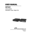
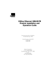
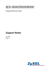
GLC1320G-55
Fiber-based, Gigabit Ethernet Line Card
Version 4.02
Edition 1, 6/2013
Quick Start Guide
User’s Guide
www.zyxel.com
Copyright © 2013 ZyXEL Communications Corporation
IMPORTANT!
READ CAREFULLY BEFORE USE.
KEEP THIS GUIDE FOR FUTURE REFERENCE.
Screenshots and graphics in this book may differ slightly from your product due to differences in
your product firmware or your computer operating system. Every effort has been made to ensure
that the information in this manual is accurate.
Related Documentation
• IES-5106M, IES-5112M, IES-6000M User’s Guides
Refer to the IES-5106M, IES-5112M, IES-6000M User’s Guide for directions on installation,
connections, maintenance, hardware trouble shooting and safety warnings.
• MSC1024GB and MSC1224GB Management Switch Card User’s Guides
These user’s guides cover the configuration of your IES-5000 or IES-6000. Refer to these user’s
guides for information on your GLC1320G-55’s default settings.
• ZyXEL Web Site
Please refer to www.zyxel.com for additional support documentation and product certifications.
2
GLC1320G-55 User’s Guide
Contents Overview
Contents Overview
Introducing the GLC1320G-55 ..................................................................................................................7
Product Specifications .............................................................................................................................15
Troubleshooting ......................................................................................................................................19
GLC1320G-55 User’s Guide
3
Contents Overview
4
GLC1320G-55 User’s Guide
Table of Contents
Table of Contents
Contents Overview .................................................................................................................. 3
Table of Contents ..................................................................................................................... 5
Chapter 1
Introducing the GLC1320G-55 ................................................................................................. 7
1.1 GLC1320G-55 Overview ........................................................................................................7
1.2 Features .................................................................................................................................7
1.3 Front Panel ..........................................................................................................................12
1.4 Ports and LEDs ....................................................................................................................13
1.4.1 Ports ...........................................................................................................................13
1.4.2 LEDs ..........................................................................................................................13
Chapter 2
Product Specifications ........................................................................................................... 15
2.1 Product Specifications ..........................................................................................................15
2.2 Firmware Naming Conventions ............................................................................................17
2.3 Console Cable Pin Assignments ..........................................................................................17
Chapter 3
Troubleshooting...................................................................................................................... 19
3.1 Power and LEDs ..................................................................................................................19
3.2 Data Transmission ...............................................................................................................20
3.3 Local Server .........................................................................................................................20
3.4 Management and Configuration ...........................................................................................21
3.4.1 Uploading the Default Configuration File via Boot Commands ..................................21
3.4.2 Uploading the Firmware via Boot Commands ............................................................22
Appendix A Legal Information................................................................................................ 25
Index ........................................................................................................................................ 29
GLC1320G-55 User’s Guide
5
Table of Contents
6
GLC1320G-55 User’s Guide
C HAPT ER
1
Introducing the GLC1320G-55
1.1 GLC1320G-55 Overview
The GLC1320G-55 is a Gigabit Ethernet Line Card with 20 SFP slot connector slots for fiber-based
SFP (mini-GBIC) transceivers (16 for SFP transceiver and 4 for CSFP/SFP). It connects through
fiber-optic cables to other Ethernet switches that support fiber connections (like the FSG1100HN,
GS2200-8 or FMG3024/3025) located at the subscriber’s premises.
Figure 1 GLC1320G-55 Overview
The GLC1320G-55 supports various SFP transceivers to satisfy a wide range of loop length
requirements (see Table 3 on page 15 for details).
The GLC1320G-55 lets you easily implement high-speed optical FTTH (Fiber To The Home) or FTTB
(Fiber To The Building) networks. The GLC1320G-55’s 1000 Mbps symmetric bandwidth persubscriber is perfect for offering IP-based triple play (voice, video, and Internet) services
The GLC1320G-55 aggregates layer-2 traffic from Ethernet subscribers to the IES system. The
GLC1320G-55’s Ethernet QoS, security, and multicast features make it easy to deploy, provide
subscribers with differentiated classes of service, and add new services.
Refer to the directions and safety warnings in the IES User's Guide to install the line card in the IES.
See the MSC User’s Guide for detailed information on configuring the line card.
1.2 Features
Here is a partial list of the GLC1320G-55’s features.
CSFP/SFP Slots
Install CSFP or SFP transceivers to connect to Ethernet switches. The Compact SFP (CSFP)
transceivers consist of two bidirectional channels inside a conventional SFP form factor.
GLC1320G-55 User’s Guide
7
Chapter 1 Introducing the GLC1320G-55
SFP Slots
Install SFP (Small Form-factor Pluggable) transceivers to connect to Ethernet switches.
Discovery and Dependency Mapping Inventory (DDMI)
Discovery and Dependency Mapping Inventory (DDMI) reads the transceiver temperature and
voltage.
SFP/CSFP Tx Manual Power Disable
Manually disables the transfer (Tx) power of individual transceivers.
Subnet Based VLAN
Subnet based VLAN allows you to group traffic into logical VLANs based on the source IP subnet you
specify. When a frame is received on a port, the GLC1320G-55 checks if a tag is added already and
the IP subnet it came from. The untagged packets from the same IP subnet are then placed in the
same subnet based VLAN. One advantage of using subnet based VLANs is that priority can be
assigned to traffic from the same IP subnet.
xVLAN
xVLAN changes the VLAN IDs (VIDs) of subscriber traffic before sending it to the service provider’s
network. It also changes the VIDs of traffic from the service provider’s network before sending it to
the subscriber. This lets you use unique VLANs for each subscriber but still deploy all the CPE
devices with the same VLAN configuration.
Upstream Broadcast Storm Control
Broadcast storm control lets you set limits for how many broadcast, multicast and destination
lookup failure (DLF) packets a port receives per second from the subscriber.
Downstream Broadcast VLAN Control
Downstream broadcast VLAN control allows you to block downstream broadcast packets from being
sent to specified VLANs on specified ports. This helps to reduce downstream bandwidth
requirements on a subscriber line.
MAC Count Limit
You can limit the number of MAC addresses that may be dynamically learned on a port. You may
enable/disable the MAC count filter on individual ports.
Rate Limiting
Rate limiting on the subscriber ports allows service providers to offer tiered service in increments of
64 Kbps. This service differentiation is not only to fulfill the needs of different customers, but also to
provide a network infrastructure that combines guaranteed performance and flexibility in service
provisioning.
8
GLC1320G-55 User’s Guide
Chapter 1 Introducing the GLC1320G-55
Loop Guard
Loop guard protects against network loops on the edge of you network.
Double Tag Mode (DT)
For untagged packets, DT adds outer VLAN tag and inner VLAN tags. For tagged packets, DT adds
an outer VLAN tag.
System Monitoring
• System status (link status, rates, statistics counters)
• Temperatures, voltage reports and alarms.
Configurable Alarms
The system allows you to customize the priority levels of individual alarms and the alarm severity
threshold for recording alarms on an individual slot(s).
Alarm LED
An ALM (alarm) LED lights when the GLC1320G-55 is overheated, the voltage readings are outside
the tolerance levels, a fan fails, or another alarm with a severity level of MAJOR or CRITICAL
occurs.
IEEE 802.1Q Tagged VLAN
Your GLC1320G-55 uses the IEEE 802.1Q Tagged VLAN (Virtual Local Area Network), which allows
it to deliver tagged/untagged frames to and from its ports. The IES supports up to 4094 individual
VLANs.
Multicast VLAN
Multicast VLAN is designed for applications (such as Media-on-Demand (MoD)) using multicast
traffic across an Ethernet ring-based service provider network. Multicast VLAN allows one single
multicast VLAN to be shared among different subscriber VLANs on the network. This improves
bandwidth utilization by reducing multicast traffic in the subscriber VLANs and simplifies multicast
group management.
IEEE 802.1x Port-based Authentication
The GLC1320G-55 supports the IEEE 802.1x standard for centralized user authentication and
accounting management through an optional network authentication (RADIUS) server.
Port Isolation
The GLC1320G-55's port isolation feature allows each port to communicate with the uplink port but
not communicate with each other. This option is the most limiting but also the most secure.
GLC1320G-55 User’s Guide
9
Chapter 1 Introducing the GLC1320G-55
Isolation (per-VLAN)
Use isolation to block the subscribers in a specific VLAN from sending traffic directly to each other.
Packet Filter
The GLC1320G-55 supports packet filtering based on protocol. You can configure the GLC1320G-55
to accept all packets, accept PPPoE packets only or block any combination of the following
protocols: IP, ARP, DHCP, EAPOL, PPPoE, NetBios or IGMP.
MAC (Media Access Control) Filters
Use the MAC filter to filter incoming frames based on MAC (Media Access Control) address(es) or
the OUI (Organizational Unit Identifier) that you specify. You may enable/disable the MAC filter on
specific ports. You may specify up to ten MAC addresses per port.
MAC (Media Access Control) Count Limit
You can limit the number of MAC addresses that may be dynamically learned on a port. You may
enable/disable the MAC count limit on individual ports.
IGMP Snooping
The GLC1320G-55 supports IGMP snooping enabling group multicast traffic to be only forwarded to
ports that are members of that group; thus allowing you to significantly reduce multicast traffic
passing through your GLC1320G-55.
IGMP Filter
The IGMP filter defines multicast groups a port can join. You can create IGMP filter profiles which
allow access to a multicast group, then assign the IGMP filter to a specific subscriber slot.
Multicast Group Limit
You can limit the number of IGMP multicast groups a subscriber on a port can join. You may enable/
disable the multicast group limit on individual ports.
Discarding of IGMP Query Messages
The GLC1320G-55 discards IGMP query messages received from subscriber ports. This prevents
subscribers from hosting IGMP multicast servers.
IGMP Statistics
The GLC1320G-55 records the number of active users in an IGMP multicast channel (multicast
group). The GLC1320G-55 also records IGMP message statistics on a per port basis to ease
management and troubleshooting.
10
GLC1320G-55 User’s Guide
Chapter 1 Introducing the GLC1320G-55
IGMP Message Rate Limiting
The GLC1320G-55 can limit how many IGMP message packets a subscriber can send per second.
This prevents subscribers from flooding the multicast server.
Static Multicast
Use static multicast to allow incoming frames based on multicast MAC address(es) that you specify.
This feature can be used in conjunction with IGMP snooping to allow multicast MAC address(es)
that are not learned by IGMP snooping. You can use static multicast to pass routing protocols, such
as RIP and OSPF.
Multicast Bandwidth Control
The GLC1320G-55 supports static bandwidth control for multicast traffic. Bandwidth limits can be
assigned to multicast channels. During IGMP snooping, the system checks the total bandwidth
usage to see if it exceeds the specified limit. If the specified limits are reached, the system restricts
the joining of multicast groups.
DHCP Relay
DHCP (Dynamic Host Configuration Protocol RFC 2131 and RFC 2132) allows individual computers
to obtain TCP/IP configuration at start-up from a server. You can configure the system as a DHCP
relay agent to have another DHCP server provide TCP/IP configuration for the clients. In addition,
you can set the system to forward client DHCP requests to specific DHCP servers based on the VLAN
ID. You can also specify up to two DHCP servers for each VLAN to provide failover protection.
DHCP Relay Option82
The system supports DHCP relay agent82 (RFC 3046) that adds additional information to client
DHCP requests that the MSC relays to a DHCP server. It also supports adding the sub-option 2
(Remote ID) with additional information.
DHCP Snooping
DHCP snooping allows the system to identify packets with DHCP server assigned IP address(es) and
block access of devices using unknown IP addresses on a subscriber port. You can also manually
add static IP addresses to the DHCP snooping table.
System Error Logging
The system error log will record error logs locally to the management switch card memory.
Remote Firmware Upgrade
You can use FTP or SFTP to perform configuration backup/restore and firmware upgrade from a
remote location.
GLC1320G-55 User’s Guide
11
Chapter 1 Introducing the GLC1320G-55
Anti-IP Address Spoofing
With DHCP snooping, the GLC1320G-55 records which IP addresses are assigned on each port. The
GLC1320G-55 drops packets from a device using a different IP address.
Anti-MAC Address Spoofing
The GLC1320G-55 checks to make sure the MAC addresses of the devices connected to the
subscriber ports are not the same as MAC addresses of devices connected to the Ethernet network.
This protects the network from disruptions of service caused by subscriber devices spoofing the
MAC address of ISP servers.
PPPoE Intermediate Agent Information
Similar to DHCP relay option82, you can set the system to insert line information into client PPPoE
Active Discovery Initialization (PADI), PPPoE Active Discovery Request (PADR), and upstream PPPoE
Active Discovery Terminate (PADT) packets. This allows a PPPoE termination server to identify and
authenticate a PPPoE client.
Transparent LAN Service (TLS)
Use TLS (also known as VLAN stacking) to add an outer VLAN tag to the inner IEEE 802.1Q tagged
frames that enter the network. By tagging the tagged frames (“double-tagged” frames), the service
provider can manage up to 4,094 VLAN groups with each group containing up to 4,094 customer
VLANs. This allows a service provider to provide different services based on specific VLANs, for
many different customers.
Classifier and Policy
You can create an ACL profile and map it to individual ports to define actions to be performed on
traffic that matches the ACL profile. The ACL profile specifies criteria such as the IP address, port
number, or protocol type, and so on.
Console Port
Use the console port for debugging and troubleshooting.
1.3 Front Panel
The figure below shows the front panel of the GLC1320G-55.
Figure 2 Front Panel
12
GLC1320G-55 User’s Guide
Chapter 1 Introducing the GLC1320G-55
1.4 Ports and LEDs
These are the details of the front panel ports and LEDs.
1.4.1 Ports
The following table describes the port labels on the front panel.
Table 1 Front Panel Ports
LABEL
DESCRIPTION
CONSOLE
For troubleshooting purposes, this mini RJ-11port connects to a computer
when the line card is not manageable from the MSC.
1-16
These are slots for SFP transceivers.
17/21-20/24
These are slots for CSFP/SFP transceivers.
1.4.2 LEDs
The following table describes the LED indicators on the front panel of the GLC1320G-55.
Table 2 LED Descriptions
LED
COLOR
STATUS
DESCRIPTION
PWR
Green
On
The line card is turned on.
Off
The line card is off.
Blinking
The line card is rebooting and performing self-diagnostic
tests.
On
The line card is on and functioning properly.
Off
The power is off or the line card is malfunctioning.
On
There is a hardware failure or an alarm.
Off
The line card is functioning normally.
On
A Ethernet link is up.
Off
The Ethernet link is down.
Blinking
The Ethernet link is transmitting/receiving Ethernet traffic.
Off
The Ethernet link is down.
On
A Ethernet link is up.
Blinking
The Ethernet link is transmitting/receiving Ethernet traffic.
Off
The Ethernet link is down.
SYS
Green
ALM
Red
LNK 1-16
Green
ACT 1-16
LNK/ACT
17-24
GLC1320G-55 User’s Guide
Green
Green
13
Chapter 1 Introducing the GLC1320G-55
14
GLC1320G-55 User’s Guide
C HAPT ER
2
Product Specifications
This chapter gives details about the line card hardware and features.
2.1 Product Specifications
Table 3 Device Specifications
Dimensions
390.6 mm (W) x 231.0 mm (D) x 24 mm (H)
Device Weight
865g
Interfaces
•
•
MAC Address Table
Up to 4 K entries
Max. Number of IGMP
Filter Profiles
128
Operating Temperature
-40º C ~ 65º C
Storage Temperature
-40º C ~ 70º C
Operating Humidity
10% ~ 90% RH (non-condensing)
Storage Humidity
10% ~ 95% RH (non-condensing)
Power Consumption
40 W
Compatible SFP
Transceivers
100BASE-FX (MMF with link span up to 2km)
16 SFP, 4 CSFP/SFP
One mini RJ11 console port for local management
100BASE-LX (SMF with link span up to 20km)
1000BASE-SX (MMF with link span up to 550m)
1000BASE-LX (SMF with link span up to 20km)
1000BASE-LHX (SMF with link span up to 40km)
Compatible CSFP
Transceivers
GLC1320G-55 User’s Guide
1000BASE-BX10-U (SMF with link span up to 20km)
1000BASE-BX10-D (SMF with link span up to 20km)
15
Chapter 2 Product Specifications
Table 3 Device Specifications
Certifications
RoHS & WEEE compliant·
ETSI 300-019 ·
Safety
EN60950-1
CSA60950-1
UL60950-1
IEC60950-1
EMC
FCC Part 15 Class A
EN55022 Class A
N55024 Class A
ETSI 300 386 Class A
Other Features
•
•
•
•
•
•
•
•
•
•
•
•
•
•
•
•
•
•
•
•
•
Anti-IP Address Spoofing
Anti-MAC Address Spoofing
MAC Filtering
MAC Count Limiting
Hardware-based Multicasting
Multicast Group Limit
IGMP Message Rate Limiting
IEEE 802.1Q VLAN Tagging
IEEE 802.1p CoS with Priority Queuing
IGMP v1 & v 2 Snooping
DHCP Relay Option82
DHCP Snooping
IEEE 802.1x Port-based Authentication
ACL profile
Upstream Broadcast Storm Control
Downstream Broadcast VLAN Control
MAC Count Limit
Rate Limiting
Loop Guard
Subnet Based VLAN
xVLAN
This table lists the standards the GLC1320G-55 supports.
Table 4 Supported Standards
16
STANDARD
DESCRIPTION
RFC 867
Daytime protocol
RFC 868
Time protocol
RFC 1305
Network Time Protocol (NTP)
RFC 1112
Internet Group Management Protocol (IGMP)
RFC 2236
IGMP v2
RFC 3376
IGMP v3
GLC1320G-55 User’s Guide
Chapter 2 Product Specifications
Table 4 Supported Standards (continued)
STANDARD
DESCRIPTION
RFC 1213
Simple Network Management Protocol (SNMP)
RFC 1573
RFC 1757
RFC 2662
RFC 2674
RFC 2863
RFC 3440
RFC 3635
RFC 3636
RFC 1483
Multiprotocol Encapsulation over ATM Adaptation Layer 5
RFC 2131
Dynamic Host Configuration Protocol (DHCP)
RFC 2132
RFC 3046
RFC 2138
Remote Authentication Dial In User Service (RADIUS)
RFC 2139
RFC 2486
Extensible Authentication Protocol (EAP)
RFC 2684
LLC and VC MUX Bridging
IEEE 802.1d
Transparent Bridging
IEEE 802.1p
Layer 2 Traffic Prioritization
IEEE 802.1Q
Virtual Local Area Network (VLAN)
IEEE 802.1x
Network Authentication
2.2 Firmware Naming Conventions
A firmware version includes the model code and release number as shown in the following example.
Firmware Version: V4.02(UHP.0)
"UHP" is the model code.
"0" is this firmware's release number. This varies as new firmware is released. Your firmware's
release number may not match what is displayed in this User's Guide.
2.3 Console Cable Pin Assignments
The following diagram and chart show the pin assignments of the console cable.
GLC1320G-55 User’s Guide
17
Chapter 2 Product Specifications
Figure 3 Console Cable Mini RJ-11 Male Connector
Table 5 Console Cable Connector Pin Assignments
MINI RJ-11 MALE
Pin 2: TXD
Pin 3: RXD
Pin 4: GND
18
GLC1320G-55 User’s Guide
C HAPT ER
3
Troubleshooting
This chapter offers some suggestions to solve problems you might encounter. The potential
problems are divided into the following categories.
• Power and LEDs
• Data Transmission
• Local Server
• Management and Configuration
3.1 Power and LEDs
The SYS or PWR LED does not turn on.
Table 6 SYS LED Troubleshooting
STEPS
CORRECTIVE ACTION
1
Make sure the power wires are properly connected to the power supply and the power
supply is operating normally. Make sure you are using the correct power source (refer to
the IES User’s Guide).
2
Make sure the power wires are connected properly.
3
Make sure the line card is properly installed.
4
The LED itself or the unit may be faulty; contact your vendor.
The ALM LED is on.
The ALM (alarm) LED lights when the line card is overheated or the voltage readings are outside
the tolerance levels.
Table 7 ALM LED Troubleshooting
STEPS
CORRECTIVE ACTION
1
Use the sys monitor status command to verify the cause of the alarm. See step 2
if the unit is overheated, and step 3 if the voltages are out of the allowed ranges.
GLC1320G-55 User’s Guide
19
Chapter 3 Troubleshooting
Table 7 ALM LED Troubleshooting
STEPS
CORRECTIVE ACTION
2
Ensure that the IES is installed in a well-ventilated area and that normal operation of the
fans is not inhibited. Keep the bottom, top and all sides clear of obstructions and away
from the exhaust of other equipment.
3
If the voltage levels are outside the allowed range, take a screen shot of the
sys
monitor status command display and contact your vendor.
3.2 Data Transmission
The link is up, but data cannot be transmitted.
Table 8 Data Transmission Troubleshooting
STEPS
CORRECTIVE ACTION
1
Check the line card’s port isolation settings.
If the subscriber is having problems with video or other high-bandwidth services, make
sure the line card’s port’s data rates are set high enough.
2
Check the VLAN configuration.
3
Ping the MSC from a computer at the subscriber’s location.
If you cannot ping, connect a Ethernet switch to a subscriber slot (that is known to
work).
If the Ethernet switch works with a different subscriber slot, there may be a problem with
the transceiver in the original SFP slot or the configuration for the SFP slot.
If using a different slot does not work, try a different Ethernet switch with the original
slot.
3.3 Local Server
The computer behind an Ethernet switch cannot access a local server connected to the line
card.
20
GLC1320G-55 User’s Guide
Chapter 3 Troubleshooting
Table 9 Local Server Troubleshooting
STEPS
CORRECTIVE ACTION
1
Refer to Section 3.2 on page 20 to make sure that the subscriber is able to transmit to
the line card.
2
Make sure the computer behind the Ethernet switch has the correct gateway IP address
configured.
3
Check the VLAN configuration (refer to the MSC User’s Guide).
4
Check the cable and connections between the line card and the local server.
5
Try to access another local server.
If data can be transmitted to a different local server, the local server that could not be
accessed may have a problem.
3.4 Management and Configuration
The line card is not manageable.
The line card always uses the default configuration. Any changes you made to the line card are
stored on the MSC. By default, the MSC is allowed to manage every line card. Use the lcman show
command on the MSC to see a line card’s connection status. If you still cannot manage the line card
from the MSC, the line card’s configuration file may be damaged or the firmware may be old, you
may need to restore the default configuration file or upload new firmware using the line card’s
console port.
Note: The MSC resets the line card after a period of inactivity on the line card. This may
damage the line card if you are uploading the default configuration file or new
firmware to the line card. Use the lcman disable <slot> command on the MSC to
prevent the MSC from managing the line card.
After you upload the file successfully, use the lcman enable <slot> command on
the MSC to allow the MSC to manage the line card again. Refer to the MSC User’s
Guide for details about commands.
3.4.1 Uploading the Default Configuration File via Boot Commands
Obtain the default configuration file, unzip it and save it in a folder. Use a console cable to connect
a computer with terminal emulation software to the line card’s console port. Pull out the line card
and push it back in, you will see the initial screen. When you see the message Press any key to
enter Debug Mode within 3 seconds press any key to enter debug mode.
To upload the configuration file, do the following:
1
Type atlc after the Enter Debug Mode message.
2
Wait for the Starting XMODEM upload message before activating XMODEM upload on your
terminal.
GLC1320G-55 User’s Guide
21
Chapter 3 Troubleshooting
3
This is an example Xmodem configuration upload using HyperTerminal. Click Transfer, then Send
File to display the following screen.
Figure 4 Example Xmodem Upload
Type the configuration file's
location, or click Browse to
search for it.
Choose the 1K Xmodem
protocol.
Then click Send.
4
After a successful configuration file upload, type atgo to restart the line card.
Bootbase Version: V1.00 | 03/23/2005 16:10:06
FLASH: AMD 32M
Hardware Version:
Serial Number:
RAM: Size = 133120 Kbytes
ZyNOS Version: V3.50(ABE.0)b3 | 05/11/2005 11:56:26
Press any key to enter debug mode within 3 seconds.
...........
Enter Debug Mode
atlc
Starting XMODEM upload (CRC mode)....
CCCC
Total 393216 bytes received.
Erasing...
...........................................................................
.....OK
atgo
3.4.2 Uploading the Firmware via Boot Commands
Usually you should use FTP with the MSC to upload the line card’s firmware. If you cannot manage
the line card from the MSC, use the following procedure to upload firmware to the line card.
1
22
Obtain the firmware file, unzip it and save it in a folder on your computer.
GLC1320G-55 User’s Guide
Chapter 3 Troubleshooting
2
Connect your computer to the console port and use terminal emulation software configured to the
following parameters:
•
VT100 terminal emulation
•
9600 bps
•
No parity, 8 data bits, 1 stop bit
•
No flow control
3
Pull out the line card and push it back in to restart it and begin a session.
4
When you see the Press any key to enter Debug Mode within 3 seconds message,
press a key to enter debug mode.
5
Type atba5 after the Enter Debug Mode message (this changes the console port speed to
115200 bps).
6
Change the configuration of your terminal emulation software to use 115200 bps and reconnect to
the line card.
7
Type atur after the Enter Debug Mode message.
8
Wait for the Starting XMODEM upload message before activating XMODEM upload on your
terminal.
9
This is an example Xmodem configuration upload using HyperTerminal. Click Transfer, then Send
File to display the following screen.
Figure 5 Example Xmodem Upload
Type the firmware file's
location, or click Browse to
search for it.
Choose the 1K Xmodem
protocol.
Then click Send.
GLC1320G-55 User’s Guide
23
Chapter 3 Troubleshooting
10 After a successful firmware upload, the line card restarts. The console port speed automatically
changes back to 9600 bps when the line card restarts.
Bootbase Version: V1.00 | 03/23/2005 16:10:06
FLASH: AMD 32M
Hardware Version:
Serial Number:
RAM: Size = 133120 Kbytes
ZyNOS Version: V3.50(ABE.0)b3 | 05/11/2005 11:56:26
Press any key to enter debug mode within 3 seconds.
...........
Enter Debug Mode
atba5
Now, console speed will be changed to 115200 bps
OK
atur
Starting XMODEM upload (CRC mode)....
CCCCCCCC
Total 2003968 bytes received.
Erasing...............................
...........................................................................
...........................................................................
...........................................................................
...........................................................................
...........................................................................
...........................................................................
.........
OK
System Reboot...
Console speed will be changed to 9600 bps
24
GLC1320G-55 User’s Guide
A PPENDIX
A
Legal Information
Copyright
Copyright © 2013 by ZyXEL Communications Corporation.
The contents of this publication may not be reproduced in any part or as a whole, transcribed,
stored in a retrieval system, translated into any language, or transmitted in any form or by any
means, electronic, mechanical, magnetic, optical, chemical, photocopying, manual, or otherwise,
without the prior written permission of ZyXEL Communications Corporation.
Published by ZyXEL Communications Corporation. All rights reserved.
Disclaimer
ZyXEL does not assume any liability arising out of the application or use of any products, or
software described herein. Neither does it convey any license under its patent rights nor the patent
rights of others. ZyXEL further reserves the right to make changes in any products described herein
without notice. This publication is subject to change without notice.
Certifications
Federal Communications Commission (FCC) Interference Statement
This device complies with Part 15 of FCC rules. Operation is subject to the following two conditions:
• This device may not cause harmful interference.
• This device must accept any interference received, including interference that may cause
undesired operations.
FCC Warning
This device has been tested and found to comply with the limits for a Class A digital switch,
pursuant to Part 15 of the FCC Rules. These limits are designed to provide reasonable protection
against harmful interference in a commercial environment. This device generates, uses, and can
radiate radio frequency energy and, if not installed and used in accordance with the instruction
manual, may cause harmful interference to radio communications. Operation of this device in a
residential area is likely to cause harmful interference in which case the user will be required to
correct the interference at his own expense.
CE Mark Warning:
This is a class A product. In a domestic environment this product may cause radio interference in
which case the user may be required to take adequate measures.
GLC1320G-55 User’s Guide
25
Appendix A Legal Information
Taiwanese BSMI (Bureau of Standards, Metrology and Inspection) A Warning:
Notices
Changes or modifications not expressly approved by the party responsible for compliance could
void the user's authority to operate the equipment.
This Class A digital apparatus complies with Canadian ICES-003.
Cet appareil numérique de la classe A est conforme à la norme NMB-003 du Canada.
Viewing Certifications
1
Go to http://www.zyxel.com.
2
Select your product on the ZyXEL home page to go to that product's page.
3
Select the certification you wish to view from this page.
ZyXEL Limited Warranty
ZyXEL warrants to the original end user (purchaser) that this product is free from any defects in
materials or workmanship for a period of up to two years from the date of purchase. During the
warranty period, and upon proof of purchase, should the product have indications of failure due to
faulty workmanship and/or materials, ZyXEL will, at its discretion, repair or replace the defective
products or components without charge for either parts or labor, and to whatever extent it shall
deem necessary to restore the product or components to proper operating condition. Any
replacement will consist of a new or re-manufactured functionally equivalent product of equal or
higher value, and will be solely at the discretion of ZyXEL. This warranty shall not apply if the
product has been modified, misused, tampered with, damaged by an act of God, or subjected to
abnormal working conditions.
Note
Repair or replacement, as provided under this warranty, is the exclusive remedy of the purchaser.
This warranty is in lieu of all other warranties, express or implied, including any implied warranty of
merchantability or fitness for a particular use or purpose. ZyXEL shall in no event be held liable for
indirect or consequential damages of any kind to the purchaser.
To obtain the services of this warranty, contact your vendor. You may also refer to the warranty
policy for the region in which you bought the device at http://www.zyxel.com/web/
support_warranty_info.php.
26
GLC1320G-55 User’s Guide
Appendix A Legal Information
Registration
Register your product online to receive e-mail notices of firmware upgrades and information at
www.zyxel.com.
Safety Warnings
For your safety, be sure to read and follow all warning notices and
instructions.
• Do NOT use this product near water, for example, in a wet basement or near a swimming pool.
• Do NOT expose your device to dampness, dust or corrosive liquids.
• Do NOT store things on the device.
• Do NOT install, use, or service this device during a thunderstorm. There is a remote risk of
electric shock from lightning.
• Connect ONLY suitable accessories to the device.
• Do NOT open the device or unit. Opening or removing covers can expose you to dangerous high
voltage points or other risks. ONLY qualified service personnel should service or disassemble this
device. Please contact your vendor for further information.
• Make sure to connect the cables to the correct ports.
• Place connecting cables carefully so that no one will step on them or stumble over them.
• Always disconnect all cables from this device before servicing or disassembling.
• Do not use the device outside, and make sure all the connections are indoors. There is a remote
risk of electric shock from lightning.
• Do NOT obstruct the device ventilation slots, as insufficient airflow may harm your device.
• Warning! To avoid risk of electric shock, remove only one card at a time and do not place fingers
or objects inside the chassis. Cover empty slots with slot covers.
"PRODUCT COMPLIES WITH 21 CFR 1040.10 AND 1040.11"
"PRODUIT CONFORME SELON 21CFR 1040.10 ET 1040.11".
CLASS 1 LASER PRODUCT
APPAREIL À LASER DE CLASSE 1
This product is recyclable. Dispose of it properly.
GLC1320G-55 User’s Guide
27
Appendix A Legal Information
28
GLC1320G-55 User’s Guide
Index
Index
A
features 7
ALM LED 19
filter, packet 10
filter protocols 10
front panel 12
B
I
bandwidth control 11
IEEE 802.1Q Tagged VLAN 9
IEEE 802.1x Port-based Authentication 9
C
isolation 9, 10
certifications 25, 26
notices 26
viewing 26
L
classifier 12
LEDs 13
console port 12, 23
LNK LED 13
copyright 25
lockout 21
log 11
D
DHCP 11
M
DHCP (Dynamic Host Configuration Protocol) 11
MAC count filter 10
DHCP Relay Option82 11
MAC count limit 8
DHCP snooping 11
MAC filter 10
disclaimer 25
multicast bandwidth control 11
double-tagged frames 12
multicast group limit 10
Multicast VLAN 9
MVLAN 9
E
error log 11
P
packet filter 10
F
policy 12
port isolation 9
FCC interference statement 25
GLC1320G-55 User’s Guide
product registration 27
29
Index
profile
VDSL 8
W
protocol filter 10
PWR LED 19
warranty 26
note 26
R
X
recovering the firmware 22
XMODEM upload 21, 23
registration
product 27
xVLAN 8
related documentation 2
S
standards, supported 16
static multicast 11
switch lockout 21
SYS LED 19
system error log 11
T
Telco-50 connector pin assignments 17
terminal emulation 23
Transparent LAN Service (TLS) 12
U
USER Telco-50 connectors 17
V
VDSL profile 8
VLAN 20
VLAN Stacking 12
VLAN stacking 12
VT100 23
30
GLC1320G-55 User’s Guide