1
®
ONline Ethernet 10BASE-FB
Module Installation and
Operation Guide
Document Number 17-00328-5
Printed February 1996
Model Number: 510M-FBP
5102M-FBP
5104M-FB1
3Com Corporation
118 Turnpike Road
Southborough, MA 01772-1886
U.S.A.
(508) 460-8900
FAX (508) 460-8950
Federal Communications Commission
Notice
standards set by the Voluntary Control Council for Interference by
Information Technology Equipment aimed at preventing radio
interference in commercial or industrial areas.
This equipment has been tested and found to comply with the
limits for a Class A digital device, pursuant to Part 15 of the FCC
Rules. These limits are designed to provide reasonable protection
against harmful interference when the equipment is operated in a
commercial environment. This equipment generates, uses, and can
radiate radio frequency energy and, if not installed and used in
accordance with the instruction manual, may cause harmful
interference to radio communications. Operation of this equipment
in a residential area is likely to cause harmful interference, in which
case you must correct the interference at your own expense.
Consequently, when the equipment is used in a residential area or
in an adjacent area, radio interference may be caused to radio and
TV receivers, and so on.
Read the instructions for correct handling.
Fiber Cable Classification Notice
Canadian Emissions Requirements
Use this equipment only with fiber cable classified by Underwriters
Laboratories as to fire and smoke characteristics in accordance
with Section 770-2(b) and Section 725-2(b) of the National
Electrical Code.
This Class A digital apparatus meets all requirements of the
Canadian Interference-Causing Equipment Regulations.
UK General Approval Statement
Cet appareil numérique de la classe A respecte toutes les exigences
du Règlement sur le matériel brouilleur du Canada.
VDE Class B Compliance
The ONcore Switching Hub, ONline System Concentrator, and
ONsemble StackSystem Hub are manufactured to the International
Safety Standard EN 60950 and are approved in the UK under the
General Approval Number NS/G/12345/J/100003 for indirect
connection to the public telecommunication network.
Hiermit wird bescheinigt, dass der 510M-FBP in Üebereinstimmung
mit den Bestimmungen der Vfg 243/1991 funkentstöert ist.
Disclaimer
Der Deutschen Bundespost wurde das Inverkehrbringen dieses
Geraetes angezeigt und die Berechtigung zur Üeberprüefung der
Serie auf Einhaltung der Bestimmungen eingeräeumt.
The information in this document is subject to change without
notice and should not be construed as a commitment by 3Com
Corporation. 3Com Corporation assumes no responsibility for any
errors that may appear in this document.
Einhaltung mit betreffenden Bestimmugen kommt darauf an, dass
geschirmte Ausfuehrungen gebraucht werden. Fuer die
Beschaffung richtiger Ausfuehrungen ist der Betreiber
verantwortlich.
Copyright Statement
This is to certify that the 510M-FBP is shielded against radio
interference in accordance with the provisions of Vfg 243/1991.
The German Postal Services have been advised that this equipment
is being placed on the market and that they have been given the
right to inspect the series for compliance with regulations.
Compliance with applicable regulations depends on the use of
shielded cables. The user is responsible for procuring the
appropriate cables.
EN55022/CISPR22 Compliance
This equipment conforms to the Class A emissions limits for a
digital device as defined by EN55022 (CISPR22).
VCCI Class 1 Compliance
©
1996 by 3Com Corporation. Printed in U.S.A. All rights reserved.
The information contained herein is the exclusive and confidential
property of 3Com Corporation. No part of this manual may be
disclosed or reproduced in whole or in part without permission
from 3Com Corporation.
Trademarks and Patents
Because of the nature of this material, numerous hardware and
software products are mentioned by name. In most, if not all
cases, these product names are claimed as trademarks by the
companies that manufacture the products. It is not the intent of
3Com Corporation to claim these names or trademarks as its own.
3Com, Artel, Boundary Routing, CardBoard, CardFacts, Galactica,
EtherDisk, EtherLink, EtherLink II, EtherLink Plus, LANplex,
LANsentry, LinkBuilder, NETBuilder, NETBuilder II, NetFacts,
ONcore, ONsemble, ORnet, Parallel Tasking, SmartAgent,
StarBridge, TokenLink, TokenLink Plus, TriChannel, and ViewBuilder
are registered trademarks of 3Com Corporation.
3Com Laser Library, 3Com OpenHub, 3TECH, FDDILink, FMS,
G-Man, MultiProbe, NetProbe, OnDeck, ONdemand, ONline,
PowerRing, StackJack, StackSystem, StackWay, Star-Tek,
SwitchCentral, and Transcend are trademarks of 3Com
Corporation.
This equipment is in the 1st Class category (information equipment
to be used in commercial or industrial areas) and conforms to the
3ComFacts and Ask3Com are service marks of 3Com Corporation.
ii ONline Ethernet 10BASE-FB Module Installation and Operation Guide
The 3Com Multichannel Architecture Communications System is
registered under U.S. Patent Number 5,301,303.
Restricted Rights
AT&T is a registered trademark of American Telephone and
Telegraph Company.
Use, duplication, or disclosure by the Government is subject to
restrictions as set forth in subparagraph (c)(1) (ii) of the Rights in
Technical Data and Computer Software clause at
DFARS 252.227-7013.
Banyan and VINES are registered trademarks of Banyan
Systems Inc.
Printed on recycled paper.
CompuServe is a registered trademark of CompuServe, Inc.
ProComm is a registered trademark of DATASTORM
TECHNOLOGIES, INC.
DATASTORM is a trademark of DATASTORM TECHNOLOGIES, INC.
DEC, DECnet, DELNI, POLYCENTER, VAX, VT100, VT220, and the
Digital logo are trademarks of Digital Equipment Corporation.
Hayes is a registered trademark of Hayes Microcomputer Products.
OpenView is a registered trademark of Hewlett-Packard Company.
Intel is a registered trademark of Intel Corporation.
AIX, IBM, and NetView are registered trademarks of International
Business Machines Corporation.
Microsoft and MS-DOS are registered trademarks of Microsoft
Corp.
Windows is a trademark of Microsoft Corp.
OSF and OSF/Motif are registered trademarks of Open Software
Foundation, Inc.
V30 is a trademark of NEC Corporation.
NetWare and Novell are registered trademarks of Novell,
Incorporated.
IPX is a trademark of Novell, Incorporated.
Retix is a registered trademark of Retix.
ROUTERXchange is a trademark of Retix.
Solaris, SPARCengine, Sun, Sun Microsystems, and SunSoft are
registered trademarks of Sun Microsystems, Inc.
ONC, OpenWindows, SunNet Manager, and SunOS are trademarks
of Sun Microsystems, Inc.
SPARCstation and SPARCompiler are licensed exclusively to Sun
Microsystems, Inc.
OPEN LOOK is a registered trademark of Unix System Laboratories,
Inc.
UNIX is a registered trademark in the United States and other
countries, licensed exclusively through X/Open Company, Ltd.
3Com registered trademarks are registered in the United States,
and may or may not be registered in other countries. Other brand
and product names may be registered trademarks or trademarks of
their respective holders.
ONline Ethernet 10BASE-FB Module Installation and Operation Guide iii
iv ONline Ethernet 10BASE-FB Module Installation and Operation Guide
Contents
How to Use This Guide
Audience . . . . . . . . . . . . . . . . . . . . . . . . . . . . . . . . . . . . . . . . . . . . . . . . . . xiii
Structure of This Guide . . . . . . . . . . . . . . . . . . . . . . . . . . . . . . . . . . . . . . . . xiv
Document Conventions . . . . . . . . . . . . . . . . . . . . . . . . . . . . . . . . . . . . . . . xv
Related Documents . . . . . . . . . . . . . . . . . . . . . . . . . . . . . . . . . . . . . . . . . . xvi
3Com Documents . . . . . . . . . . . . . . . . . . . . . . . . . . . . . . . . . . . . . . . . xvi
Reference Documents . . . . . . . . . . . . . . . . . . . . . . . . . . . . . . . . . . . . . xvii
Chapter 1 — Introduction
10BASE-FB Module Descriptions . . . . . . . . . . . . . . . . . . . . . . . . . . . . . . . . . 1-2
10BASE-FB Compliance . . . . . . . . . . . . . . . . . . . . . . . . . . . . . . . . . . . . . . . . 1-4
Theory of Operation . . . . . . . . . . . . . . . . . . . . . . . . . . . . . . . . . . . . . . . . . . 1-4
Compatibility With Other Ethernet Fiber Products . . . . . . . . . . . . . . . . . . . . 1-6
Chapter 2 — Designing and Expanding the Network
Understanding the General Rules . . . . . . . . . . . . . . . . . . . . . . . . . . . . . . . . 2-2
Rules for Configuring a Network . . . . . . . . . . . . . . . . . . . . . . . . . . . . . 2-2
Equivalent Fiber Distances . . . . . . . . . . . . . . . . . . . . . . . . . . . . . . . . . . 2-5
Determining Maximum Fiber Link Distances . . . . . . . . . . . . . . . . . . . . . . . . 2-6
Calculating Maximum Link Distance . . . . . . . . . . . . . . . . . . . . . . . . . . . 2-7
Determining Link Budget . . . . . . . . . . . . . . . . . . . . . . . . . . . . . . . . . . . 2-7
Attenuation . . . . . . . . . . . . . . . . . . . . . . . . . . . . . . . . . . . . . . . . . 2-10
Splicing . . . . . . . . . . . . . . . . . . . . . . . . . . . . . . . . . . . . . . . . . . . . 2-10
Optical Fiber Loss . . . . . . . . . . . . . . . . . . . . . . . . . . . . . . . . . . . . . 2-11
Maximum Link Distance Calculation . . . . . . . . . . . . . . . . . . . . . . . 2-12
Choosing a Network Backbone Cabling Structure . . . . . . . . . . . . . . . . . . . 2-14
Star Configuration . . . . . . . . . . . . . . . . . . . . . . . . . . . . . . . . . . . . . . . 2-15
Serial Configuration . . . . . . . . . . . . . . . . . . . . . . . . . . . . . . . . . . . . . . 2-16
10BASE-FB Module Configurations . . . . . . . . . . . . . . . . . . . . . . . . . . . . . . 2-17
Fiber Backbone, Fiber-to-the-Desk . . . . . . . . . . . . . . . . . . . . . . . . . . . . 2-17
ONline Ethernet 10BASE-FB Module Installation and Operation Guide v
Network Distance Calculation Examples . . . . . . . . . . . . . . . . . . . . 2-19
Fiber Backbone, Unshielded Twisted Pair to-the-Desk . . . . . . . . . . . . . 2-22
Fiber Backbone, Coaxial Connection . . . . . . . . . . . . . . . . . . . . . . . . . . 2-24
Fault-Tolerant Configurations . . . . . . . . . . . . . . . . . . . . . . . . . . . . . . . . . . 2-26
Configuring Ports for Fault Tolerance . . . . . . . . . . . . . . . . . . . . . . . . . 2-26
Setting Redundancy . . . . . . . . . . . . . . . . . . . . . . . . . . . . . . . . . . . 2-27
Implementing Total Backbone Fault Tolerance . . . . . . . . . . . . . . . . . . 2-29
Chapter 3 — Installing and Operating the Module
Precautionary Procedures . . . . . . . . . . . . . . . . . . . . . . . . . . . . . . . . . . . . . . 3-2
Unpacking Procedures . . . . . . . . . . . . . . . . . . . . . . . . . . . . . . . . . . . . . . . . 3-3
Quick Installation . . . . . . . . . . . . . . . . . . . . . . . . . . . . . . . . . . . . . . . . . . . . 3-4
Setting the Dip Switches . . . . . . . . . . . . . . . . . . . . . . . . . . . . . . . . . . . . . . 3-5
Setting Dip Switch S1 . . . . . . . . . . . . . . . . . . . . . . . . . . . . . . . . . . . . . . 3-7
Setting Dip Switch S2 . . . . . . . . . . . . . . . . . . . . . . . . . . . . . . . . . . . . . . 3-9
Installing the Module . . . . . . . . . . . . . . . . . . . . . . . . . . . . . . . . . . . . . . . . 3-10
Configuring the Module . . . . . . . . . . . . . . . . . . . . . . . . . . . . . . . . . . . . . . 3-13
Enabling Ports . . . . . . . . . . . . . . . . . . . . . . . . . . . . . . . . . . . . . . . . . . 3-14
Selecting a Network . . . . . . . . . . . . . . . . . . . . . . . . . . . . . . . . . . . . . . 3-15
Enabling Port Redundancy . . . . . . . . . . . . . . . . . . . . . . . . . . . . . . . . . 3-16
Enabling Low Light Warning . . . . . . . . . . . . . . . . . . . . . . . . . . . . . . . . 3-17
Enabling Optical Power . . . . . . . . . . . . . . . . . . . . . . . . . . . . . . . . . . . 3-17
Saving Module Configuration . . . . . . . . . . . . . . . . . . . . . . . . . . . . . . . 3-18
Showing Module Configuration . . . . . . . . . . . . . . . . . . . . . . . . . . . . . . . . 3-18
Monitoring the Front Panel . . . . . . . . . . . . . . . . . . . . . . . . . . . . . . . . . . . . 3-19
Verifying LED and Network Assignments . . . . . . . . . . . . . . . . . . . . . . . . . 3-22
Chapter 4 — Troubleshooting
Troubleshooting Using the Port Activity LEDs . . . . . . . . . . . . . . . . . . . . . . . 4-2
Troubleshooting Using the Port Status LEDs . . . . . . . . . . . . . . . . . . . . . . . . 4-3
Technical Assistance . . . . . . . . . . . . . . . . . . . . . . . . . . . . . . . . . . . . . . . . . . 4-7
vi ONline Ethernet 10BASE-FB Module Installation and Operation Guide
Appendix A — Specifications
General Specifications . . . . . . . . . . . . . . . . . . . . . . . . . . . . . . . . . . . . . . .
Optical Specifications . . . . . . . . . . . . . . . . . . . . . . . . . . . . . . . . . . . . . . . .
Transmitter Specifications . . . . . . . . . . . . . . . . . . . . . . . . . . . . . . . . . .
Receiver Specifications . . . . . . . . . . . . . . . . . . . . . . . . . . . . . . . . . . . .
Supported Fiber Optic Cables . . . . . . . . . . . . . . . . . . . . . . . . . . . . . . .
Fiber Optic Interface . . . . . . . . . . . . . . . . . . . . . . . . . . . . . . . . . . . . . .
Power Requirements . . . . . . . . . . . . . . . . . . . . . . . . . . . . . . . . . . . . . . . .
Environmental Specifications . . . . . . . . . . . . . . . . . . . . . . . . . . . . . . . . . .
Mechanical Specifications . . . . . . . . . . . . . . . . . . . . . . . . . . . . . . . . . . . . .
3Com 10BASE-FB Network Products . . . . . . . . . . . . . . . . . . . . . . . . . . . . .
10BASE-FB Cable and Connector Specifications . . . . . . . . . . . . . . . . . . . . .
10BASE-FB Cables . . . . . . . . . . . . . . . . . . . . . . . . . . . . . . . . . . . . . . .
10BASE-FB Connectors . . . . . . . . . . . . . . . . . . . . . . . . . . . . . . . . . . . .
Connecting Fiber Cables . . . . . . . . . . . . . . . . . . . . . . . . . . . . . . . .
A-2
A-3
A-3
A-4
A-4
A-5
A-5
A-6
A-6
A-6
A-7
A-7
A-8
A-8
Appendix B — Technical Support
On-line Technical Support . . . . . . . . . . . . . . . . . . . . . . . . . . . . . . . . . . . . . . B-1
Email Technical Support . . . . . . . . . . . . . . . . . . . . . . . . . . . . . . . . . . . . B-2
World Wide Web Site . . . . . . . . . . . . . . . . . . . . . . . . . . . . . . . . . . . . . . B-2
Support from Your Network Supplier . . . . . . . . . . . . . . . . . . . . . . . . . . . . . B-2
Support from 3Com . . . . . . . . . . . . . . . . . . . . . . . . . . . . . . . . . . . . . . . . . . B-3
Returning Products for Repair . . . . . . . . . . . . . . . . . . . . . . . . . . . . . . . . . . . B-4
Accessing the 3Com MIB . . . . . . . . . . . . . . . . . . . . . . . . . . . . . . . . . . . . . . B-4
3Com Technical Publications . . . . . . . . . . . . . . . . . . . . . . . . . . . . . . . . . . . . B-5
Index
ONline Ethernet 10BASE-FB Module Installation and Operation Guide vii
viii ONline Ethernet 10BASE-FB Module Installation and Operation Guide
Figures
Figure 1-1.
Figure 2-1.
Figure 2-2.
Figure 2-3.
Figure 2-4.
Figure 2-5.
Figure 2-6.
Figure 2-7.
Figure 2-8.
Figure 2-9.
Figure 2-10.
Figure 2-11.
Figure 2-12.
Figure 3-1.
Figure 3-2.
Figure 3-3.
Figure 3-4.
10BASE-FB Module Connections . . . . . . . . . . . . . . . . . . . . . 1-5
1700 Meter Fiber Link With Mechanical Splice . . . . . . . . . 2-12
2000 Meter Fiber Link Through Two Patch Panels . . . . . . . 2-13
Star-Wiring Configuration . . . . . . . . . . . . . . . . . . . . . . . . . 2-15
Serial Configuration Using 10BASE-FB Modules . . . . . . . . . 2-16
All-Fiber Network . . . . . . . . . . . . . . . . . . . . . . . . . . . . . . . 2-18
Network With 3 Concentrators . . . . . . . . . . . . . . . . . . . . . 2-19
Network Configured With 8 Concentrators . . . . . . . . . . . . 2-20
Sample Configuration Distance Calculation . . . . . . . . . . . . 2-23
Thin Ethernet Segment Connected to an ONline
10BASE-FB Module . . . . . . . . . . . . . . . . . . . . . . . . . . . . . . 2-24
Redundant Fiber Backbone Configuration . . . . . . . . . . . . . 2-28
Total Backbone Fault-Tolerant Configuration . . . . . . . . . . . 2-30
Fiber Network With 3 Concentrators . . . . . . . . . . . . . . . . 2-31
10BASE-FB Module Dip Switch Locations . . . . . . . . . . . . . . 3-6
Installing the 10BASE-FB Module . . . . . . . . . . . . . . . . . . . 3-11
10BASE-FB Module Connection . . . . . . . . . . . . . . . . . . . . 3-12
10BASE-FB Port-Switching Module Faceplate and
ONline System Concentrator . . . . . . . . . . . . . . . . . . . . . . 3-20
ONline Ethernet 10BASE-FB Module Installation and Operation Guide ix
x ONline Ethernet 10BASE-FB Module Installation and Operation Guide
Tables
Table 1-1.
Table 2-1.
Table 2-2.
Table 2-3.
Table 2-4.
Table 2-5.
Table 2-6.
Table 2-7.
Table 2-8.
Table 3-1.
Table 3-2.
Table 3-3.
Table 3-4.
Table 3-5.
Table 3-6.
Table 4-1.
Table 4-2.
10BASE-FB Module Compatibility. . . . . . . . . . . . . . . . . . . . . 1-6
Basic Network Rules . . . . . . . . . . . . . . . . . . . . . . . . . . . . . . 2-2
Equivalent Fiber Distances of LAN Products . . . . . . . . . . . . . 2-5
ONline 10BASE-FB Module Optical Power Budget:
Normal Power . . . . . . . . . . . . . . . . . . . . . . . . . . . . . . . . . . . 2-8
ONline 10BASE-FB Module Optical Power Budget:
High Power . . . . . . . . . . . . . . . . . . . . . . . . . . . . . . . . . . . . . 2-9
10BASE-FB Optical Power Budget . . . . . . . . . . . . . . . . . . . . 2-9
Connector and Splice Insertion Loss. . . . . . . . . . . . . . . . . . 2-11
Typical Fiber Loss Characteristics . . . . . . . . . . . . . . . . . . . . 2-11
Fiber Equivalent Distances Between Transceivers . . . . . . . . 2-21
Quick Installation Procedures. . . . . . . . . . . . . . . . . . . . . . . . 3-4
Dip Switch S1 Settings for Switches 1 and 2 . . . . . . . . . . . . 3-7
Dip Switch S1 Settings for Switches 3 to 10. . . . . . . . . . . . . 3-8
Dip Switch S2 Settings . . . . . . . . . . . . . . . . . . . . . . . . . . . . 3-9
Interpreting the 10BASE-FB Module LEDs. . . . . . . . . . . . . . 3-21
Network Check Codes . . . . . . . . . . . . . . . . . . . . . . . . . . . . 3-22
Troubleshooting Using the Port Activity LEDs . . . . . . . . . . . . 4-2
Troubleshooting Using the Port Status LEDs. . . . . . . . . . . . . 4-3
ONline Ethernet 10BASE-FB Module Installation and Operation Guide xi
How to Use This Guide
This guide is designed to help you understand the features, indicators, and
installation procedures for the:
❑
3Com ONline™ Ethernet Port-Switching 10BASE-FB Modules (Model
Numbers 5102M-FBP and 5104M-FBP)
❑
3Com ONline™ Ethernet 10BASE-FB Module (Model Number
5104M-FB1)
This guide also contains information on troubleshooting and diagnostics for
operation verification. In addition, a configuration section provides you
with network configuration information.
Audience
This guide contains instructions for installing the modules and maintaining
normal operation. It is intended for the following people at your site:
❑
Hardware installer
❑
System/Network manager
ONline Ethernet 10BASE-FB Module Installation and Operation Guide xiii
Structure of This Guide
This guide contains the following chapters:
Chapter 1, Introduction – Introduces the principal features of the ONline
Ethernet Port-Switching 10BASE-FB Modules and the ONline Ethernet
10BASE-FB Module.
Chapter 2, Designing and Expanding the Network – Contains
configuration information to help you integrate the 10BASE-FB Modules
into your Ethernet network.
Chapter 3, Installing and Operating the Module – Provides illustrated
procedures for installing the 10BASE-FB Modules into the ONline System
Concentrator and configuring them for operation. This chapter also
provides a front panel view of the 10BASE-FB Modules showing ports, LEDs,
and dip switches.
Chapter 4, Troubleshooting – Provides help in isolating and correcting
problems that could arise during the installation process and during normal
operation.
Appendix A, Specifications – Describes product dimensions, power
requirements, and other specifications for the modules.
Appendix B, Technical Support – Lists the various methods for
contacting the 3Com technical support organization and for accessing
other product support services.
Index – Contains an alphabetical list of important terms and features
referenced throughout this guide.
xiv ONline Ethernet 10BASE-FB Module Installation and Operation Guide
Document Conventions
The following document conventions are used in this manuall:
Convention
Courier text
Indicates
Example
User input
In the Agent Information Form,
enter MIS in the New Contact
field.
System output
After pressing the Apply
button, the system displays
the message
Transmitting data.
Bold command
string
Path names
Before you begin, read the
readme.txt file located in
/usr/snm/agents.
Text in angled
brackets
User-substituted
identifiers
In the command above,
substitute <rem_name> with
the name of the remote
machine.
Capitalized text in
plain brackets
Keyboard entry
by the user
Type your password and press
[ENTER].
Italics
Text emphasis,
document titles
Ensure that you press the Apply
button after you add the new
search parameters.
ONline Ethernet 10BASE-FB Module Installation and Operation Guide xv
Convention
Indicates
Example
Note:
A Note. The
information is
important
Note: Use STP lobe
cables for your system.
Caution:
A Caution. A
condition may
damage
software or
hardware
Caution: Do not put
your installation
diskettes on a
magnetic surface.
This may damage the
diskettes.
Warning: A Warning. A
condition may
threaten
personal safety
Warning: Wear eye
protection when
performing these
maintenance
procedures.
Related Documents
This section provides information on supporting documentation, including:
❑
3Com Documents
❑
Reference Documents
3Com Documents
The following documents provide additional information on 3Com
products:
17-Slot ONline System Concentrator Installation and Operation
Guide – Explains how to install, operate, and manage the 3Com ONline
17-Slot System Concentrator (Models 5017C-LS and 5017C with load
sharing).
xvi ONline Ethernet 10BASE-FB Module Installation and Operation Guide
6-Slot ONline System Concentrator Installation and Operation
Guide – Explains how to install, operate, and manage the 3Com ONline
6-Slot System Concentrator.
ONline Ethernet Management Module Installation and Operation Guide –
Describes how to install the ONline Ethernet Management Module in the
ONline System Concentrator and explains the LEDs on the module
faceplate. This guide also provides instructions for connecting a terminal to
the module and describes the management commands necessary to
perform management tasks on the concentrator and on remote devices.
ONline Management Commands Guide – Provides an alphabetized
reference resource describing all ONline management commands.
For a complete list of 3Com documents, contact your 3Com representative.
Reference Documents
The following documents supply related background information:
Case, J., Fedor, M., Scoffstall, M., and J. Davin, The Simple Network
Management Protocol, RFC 1157, University of Tennessee at Knoxville,
Performance Systems International and the MIT Laboratory for Computer
Science, May 1990.
Rose, M., and K. McCloghrie, Structure and Identification of
Management Information for TCP/IP-based Internets, RFC 1155,
Performance Systems International and Hughes LAN Systems, May 1990.
ONline Ethernet 10BASE-FB Module Installation and Operation Guide xvii
1
Introduction
This chapter introduces you to the:
❑
3Com ONline™ Ethernet Port-Switching 10BASE-FB Modules
(5102M-FBP and 5104M-FBP)
❑
3Com ONline™ Ethernet 10BASE-FB Module (5104M-FB1)
The modules are referred throughout this guide as the 10BASE-FB Modules.
Information in this guide refers to all three 10BASE-FB Modules listed above.
Differences between the modules are noted where applicable.
This chapter contains the following sections:
❑
10BASE-FB Module Descriptions
❑
10BASE-FB Compliance
❑
10BASE-FB Theory of Operation
❑
Compatibility With Other Ethernet Fiber Products
Introduction 1 - 1
10BASE-FB Module Descriptions
The ONline Ethernet Port-Switching 10BASE-FB Module is a 2- or 4-port,
Ethernet fiber module designed for 3Com ONline System Concentrators.
The ONline Ethernet 10BASE-FB Module is a 4-port, Ethernet fiber module
also designed for 3Com ONline System Concentrators.
The ONline Ethernet Port-Switching 10BASE-FB Module (Model Number
5104M-FBP) is functionally identical to the ONline Ethernet 10BASE-FB
Module (Model Number 5104M-FB1) except for the Port-Switching
Module's ability to set each port to an independent backplane network in
the concentrator.
The 5104M-FB1 is module-switching only. You can update the 10BASE-FB
Module to a port-switching module by installing the ONline Ethernet
10BASE-FB Upgrade Kit.
The 10BASE-FB Modules provide:
❑
Fiber backbone connectivity for Ethernet local area networks
❑
Direct fiber to-the-desk connectivity
You can directly connect the 10BASE-FB Modules to any other ONline fiber
module as well as all of the products in the 3Com 10BASE-FB family,
including the:
❑
3Com 10BASE-FB Star Coupler
❑
3Com 10BASE-FB Fiber Transceiver
❑
3Com Fault-Tolerant 10BASE-FB Transceiver
The 10BASE-FB Modules:
❑
Provide up to 4.0 kilometers distance between any two concentrators
❑
Support network diameters up to 4.2 kilometers
❑
Contain built-in link redundancy for fault tolerance
1 - 2 ONline Ethernet 10BASE-FB Module Installation and Operation Guide
❑
Include diagnostics for troubleshooting
❑
Provide 10 Mbps performance with 100 percent collision detection
using CSMA/CD
❑
Support 50, 62.5, 85, and 100 µm fiber cable
❑
Are shipped with either ST, SMA, or FC-type connectors
Other benefits of the 10BASE-FB Modules include:
❑
3Com TriChannel Architecture - The 10BASE-FB Modules operate in
an ONline System Concentrator with all ONline modules, including
Token Ring and FDDI.
❑
Slot Independence - You can install modules into any available slot
in the ONline Concentrator. This flexibility eliminates the need to shut
down the network and rearrange the existing configuration of the
concentrator when you install new modules into the concentrator.
❑
“Hot Swap” Capability - You can install or remove modules from
the ONline System Concentrator when it is powered up without
affecting the operation of any other modules in the concentrator.
❑
Independent Networks - You can assign each module to any of
three independent Ethernet networks.
❑
Management Support - You can manage the module through the
3Com ONdemand™ Network Control System. You may also manage
the 10BASE-FB modules using terminal management through an
ONline network management module.
❑
Compliance - The 10BASE-FB Modules comply with the IEEE
10BASE-FB fiber standard to provide interoperability with other
standards-based products.
Introduction 1 - 3
10BASE-FB Compliance
The ONline Ethernet Port-Switching 10BASE-FB Modules and the ONline
Ethernet 10BASE-FB Module are fully compliant with the IEEE 10BASE-FB
fiber standard. The IEEE ratification of the 10BASE-FB standard validates
synchronous fiber Ethernet as the choice for backbone links. Synchronous
technology provides robust transmission for fiber Ethernet backbones.
Compliance with the 10BASE-FB standard allows 3Com fiber modules to be
compatible with:
❑
Industry 10BASE-FB-compliant products
❑
Existing 3Com 10BASE-FB technology
3Com 10BASE-FB Modules implement Ethernet/IEEE 802.3 physical layer
functionality on a fiber optic medium. Full interconnection of all devices
that comply with Ethernet V2.0 or IEEE 802.3 specifications are provided,
including:
❑
Minicomputers
❑
Engineering workstations
❑
PC networking servers
❑
Bridges
Theory of Operation
The 10BASE-FB Modules serve mainly as network backbone links. Network
backbone links connect concentrators together. You may also use the
10BASE-FB Modules to connect directly to devices using the:
❑
3Com 5101T-FB Transceiver
❑
3Com 5102T-FBFT Fault-Tolerant Transceiver
1 - 4 ONline Ethernet 10BASE-FB Module Installation and Operation Guide
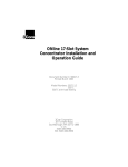
Figure 1-1 illustrates a configuration using fiber transceivers and the
10BASE-FB Modules to connect concentrators and devices
.
Figure 1-1. 10BASE-FB Module Connections
Introduction 1 - 5
Compatibility With Other Ethernet Fiber Products
The 10BASE-FB Modules are compatible with the 3Com products outlined in
Table 1-1.
Table 1-1. 10BASE-FB Module Compatibility
3Com Product
Part Number
10BASE-FB Star Coupler
9308S-FB
10BASE-FB Transceiver
5101T-FB
Fault-Tolerant 10BASE-FB Transceiver
5102T-FBFT
From the backplane interface, you can also connect the 10BASE-FB Modules
to other Ethernet modules on the same network.
Caution:
The 10BASE-FB Modules are not compatible with the
ONline Ethernet 10BASE-FL Module (Model Number
5104M-FL1). The 4-port10BASE-FL Module faceplate is
similar to the 10BASE-FB Modules, but the two modules
cannot communicate.
1 - 6 ONline Ethernet 10BASE-FB Module Installation and Operation Guide
2
Designing and
Expanding the Network
This chapter contains configuration information to help you design your
network. It describes how to configure networks using the ONline System
Concentrator and the ONline 10BASE-FB Modules. It also provides
examples of network cabling structures and Ethernet network cabling
solutions.
This chapter contains the following sections:
❑
Understanding the General Rules
❑
Determining Maximum Fiber Link Distances
❑
Choosing a Network Backbone Cabling Structure
❑
10BASE-FB Module Configurations
❑
Fault-Tolerant Configurations
Note: To ensure proper operation of your network, install all
equipment using only approved cables. Refer to Appendix
A for information on cable requirements.
Designing and Expanding the Network 2 - 1
Understanding the General Rules
This section describes general rules for configuring an Ethernet network
using fiber as the backbone medium. It also provides rules to ensure that
your network configuration conforms to distance limitations imposed by
Ethernet and networking equipment. Use these guidelines for building
your network.
Refer to the sections that follow for specific rules for:
❑
Determining maximum 10BASE-FB fiber link distances
❑
Connecting various horizontal media types (10BASE-FB, twisted pair)
to a 10BASE-FB backbone
❑
Examples of recommended fault-tolerant configurations
Rules for Configuring a Network
This section outlines the network rules and recommendations for building
an Ethernet network. For more hardware-specific information on the
10BASE-FB, refer to Appendix A.
Table 2-1. Basic Network Rules
Rule
1
Definition
Use 10BASE-FB as the
backbone medium.
Recommendations/Notes
Use 62.5 micron cable to
conform with the IEEE 10BASE-F
and ANSI FDDI standards.
Use ST-type connectors.
2
Wire the backbone in a
star topology to isolate
faults.
Lay extra fiber cables. The extra
cost is small and you will need
them as your network grows.
2 - 2 ONline Ethernet 10BASE-FB Module Installation and Operation Guide
Table 2-1. Basic Network Rules (Continued)
Rule
Definition
Recommendations/Notes
2
(con’t)
Wire the backbone in a
star topology to isolate
faults.
The star topology conforms to
FDDI wiring. Run at least two
fiber strands to each backbone
connection.
3
Do not exceed the
maximum Fiber Ethernet
network diameter of
4200 meters of fiber
cable.
The 4200 meters is the
maximum distance between
any two transceivers on the
network.
4
Certain LAN products
on the network shrink
the maximum Fiber
Ethernet network
diameter to less than
4200 meters.
The 4200 meters does not
include the transceiver cable
that connects a device with an
external transceiver.
Transceiver cable can extend up
to 50 meters. Thus, total
network diameter can be as
much as 4300 meters (4200 m +
2 * 50 m) between any two
modes.
Each microsecond delay
through a device on the
network shrinks the network
diameter by approximately 200
meters of fiber cable. This
reduction is known as
equivalent distance. Table 2-2
lists the equivalent fiber
distances for 3Com ONline LAN
products.
Designing and Expanding the Network 2 - 3
Table 2-1. Basic Network Rules (Continued)
Rule
Definition
Recommendations/Notes
5
Assume that one meter
of coaxial or twisted
pair cable is equal to
one meter of fiber
cable.
This is a conservative
equivalence. One meter of fiber
is actually equal to 1.1 meters of
coaxial. For simplicity, assume
one meter.
6
Verify that the
10BASE-FB link
distances do not
exceed the limits
imposed by the optical
power budget.
In general, on 62.5 cable, use
up to 4000 meters
point-to-point using the
10BASE-FB Modules. If you
have poor quality cable or
numberous patch panels, you
may have to sacrifice some
distance.
Some older Ethernet fiber optic
products are less powerful than
ONline 10BASE-FB Module
optics. When connecting to
these products, remember that
they determine the maximum
point-to-point distance.
7
When in doubt, use a
bridge.
If you are not certain you have
exceeded acceptable network
distances, use a bridge to
extend the network.
2 - 4 ONline Ethernet 10BASE-FB Module Installation and Operation Guide
Equivalent Fiber Distances
Equivalent fiber distance is the sum of both the incoming and outgoing
module port signals. Different products, however, have different
equivalent distances. Table 2-2 lists the equivalent fiber distance of 3Com
ONline LAN products.
Table 2-2. Equivalent Fiber Distances of LAN Products
LAN Product
Equivalent Fiber
Distance (meters)
ONline Ethernet 10BASE-FB Modules
(5104M-FB1, 5102M-FBP, 5104M-FBP)
190
Incoming signal to fiber port
140
Outgoing signal from fiber port
50
ONline Ethernet 10BASE-FL Module (5104M-FL1)
560
Incoming signal to fiber port
330
Outgoing signal from fiber port
230
ONline Ethernet 10BASE-T Module (5108M-TP)
585
Incoming signal to TP port
420
Outgoing signal from TP port
165
ONline Ethernet 50-Pin Module
(5112M-TPL, 5112M-TPPL)
585
Incoming signal to TP port
420
Outgoing signal from TP port
165
ONline Ethernet 24-Port Module (5124M-TPCL,)
585
Incoming signal to TP port
420
Outgoing signal from TP port
165
Designing and Expanding the Network 2 - 5
Table 2-2. Equivalent Fiber Distances of LAN Products (Continued)
LAN Product
Equivalent Fiber
Distance (meters)
ONline Ethernet Repeater Module (5102M-AUIF)
800
Incoming signal to AUI port
600
Outgoing signal from AUI port
200
ONline Ethernet BNC Module (5106M-BNC)
900
Incoming signal to BNC port
450
Outgoing signal from BNC port
450
ONline Ethernet Transceiver Module (5103M-AUIM)
0
3Com 10BASE-FB Star Coupler (9308S-FB)
180
10BASE-FB Star Coupler (9314S)
180
IEEE Repeater
800
Determining Maximum Fiber Link Distances
This section describes how to calculate the maximum allowable link
distances between two fiber ports. To do this, you must know the
following information:
❑
10BASE-FB optical power budget
❑
Fiber cable diameter (for example, 50 micron, 62.5 micron)
❑
Fiber cable light loss/km (for example, 3 dB loss/km)
❑
Number of patch panel connections and link splices
2 - 6 ONline Ethernet 10BASE-FB Module Installation and Operation Guide
The following tables assist you in obtaining this information:
❑
Table 2-3 - Lists the optical power budget for the 10BASE-FB Module
❑
Table 2-6 - List typical losses for connector and splice insertion loss
❑
Table 2-7 - Lists typical losses for various fiber cables
Calculating Maximum Link Distance
To calculate the maximum link distance allowed:
1. Determine the optical power budget for the 10BASE-FB
port (Table 2-3).
2. Subtract the optical power loss due to patch panels and splices
(Table 2-6) from the optical power budget for the 10BASE-FB port.
3. Subtract the dB loss/km rating of the fiber cable (Table 2-7) from the
remainder of step 2. If the result is greater than 0, the link distance is
valid.
4. If the device connecting to the 10BASE-FB Module does not have the
same optical budget as the 10BASE-FB Module, you must also
calculate the maximum link distance for the connecting device.
Determining Link Budget
To ensure link integrity, you should plan for worst case losses through the
end-to-end optical connection. The optical power budget represents a
worst case that assumes the transmitter is transmitting at the low end of its
range. When possible, 3Com recommends using Normal power.
Designing and Expanding the Network 2 - 7
Table 2-3 provides the transmit optical power ranges and required receiver
optical power budget levels for the 10BASE-FB Modules.
Table 2-3. ONline 10BASE-FB Module Optical Power Budget:
Normal Power
Cable
Size
Used
(micron)
Transmit
Power
Range
(dBm)
Receive
Power
Range
(dBm)
Optical
Power
Budget
(dB)
Link
Loss
Required
(dB)
(ONline to
ONline)
Link Loss
Required
(dB)
(ONline to
10BASE-FB)
50/125
NA
0.20
-21.5 ±
3.0
-8.0 to
-30.0
5.5
None
None
62.5/125
NA
0.275
-17.0 ± 3.0
-8.0 to
-30.0
10.0
None
None
85/125
NA
0.29
-14.0 ±
3.0
-8.0 to
-30.0
13.0
None
>3.0
100/140
NA
0.29
-11.5 ± 3.0
-8.0 to
-30.0
15.5
None
>5.5
Table 2-4 provides 10BASE-FB Module optical power budget values for high
power.
2 - 8 ONline Ethernet 10BASE-FB Module Installation and Operation Guide
Table 2-5 provides information on the 10BASE-FB-specific optical power
budget.
Table 2-4. ONline 10BASE-FB Module Optical Power Budget:
High Power
Optical
Power
Budget
(dB)
Link Loss
Required
(dB)
(ONline to
ONline)
Link Loss
Required
(dB)
(ONline to
10BASE-F
B)
-8.0 to
-30.0
13.5
None
>2.0
-10.0 ±
2.25
-8.0 to
-30.0
17.75
>0.25
>6.25
85/125
NA 0.29
-7.0 ±
2.25
-8.0 to
-30.0
20.75
>3.25
>9.25
100/140
NA 0.29
-4.5 ±
2.25
-8.0 to
-30.0
23.25
>5.75
>11.75
Cable
Size
Used
(micron)
Transmit
Power
(dBm)
Receive
Power
(dBm)
50/125
NA 0.20
-14.25 ±
2.25
62.5/125
NA
0.275
Table 2-5. 10BASE-FB Optical Power Budget
Cable Size Used
(micron)
Transmit
Power
(dBm)
Receive
Power
(dBm)
Optical
Power
Budget (dB)
50/125 (NA 0.20)
-20.0 ± 1.0
-14.0 to 29.0
8.0
62.5/125(NA 0.275)
-15.1 ± 1.0
-14.0 to 29.0
12.9
85/125 (NA 0.29)
-13.1 ± 1.0
-14.0 to 29.0
14.9
100/140 (NA 0.29)
-11.6 ± 1.0
-14.0 to 29.0
16.4
Designing and Expanding the Network 2 - 9
Attenuation
It is possible for receivers to receive too much light when:
❑
Using 85/125 and 100/140 micron fiber cables
❑
Ports are close together on a link
Receivers can also receive too much light on 62.5 micron fiber and High
power on the 10BASE-FB Modules when:
❑
Connecting to an 10BASE-FB product (6.25 dB loss required)
❑
Connecting to another 10BASE-FB Module (.25 dB loss required)
In these two situations, switch the 10BASE-FB Module to Normal power.
In all of the cases listed above, some attenuation is required to prevent this
problem. This attenuation is covered by:
❑
A moderate link length
❑
The fiber optic connectors
Splicing
Many fiber optic installations employ the use of patch panels to manage
expansion and topological changes. A typical patch panel consists of a set
of female to female bulkhead barrel connectors used to connect male fiber
connectors on both sides. The optical power loss through a patch panel
therefore includes two connectors and a bulkhead.
If a fiber optic cable breaks, the break is usually fixed by splicing the broken
ends together. Use one of the following types of splicing methods:
❑
Fusion – A fusion splice usually offers lower power loss, but the
fusion equipment is often bulky and costly.
❑
Mechanical – A mechanical splice can be conveniently used in the
field when a fusion splice is not available. If a repair is made, make
sure that the fiber cable still meets the power loss guidelines.
2 - 10 ONline Ethernet 10BASE-FB Module Installation and Operation Guide
Table 2-6 shows the range of loss and the typical loss as a result of splices.
Table 2-6. Connector and Splice Insertion Loss
Connector Type
Range of Loss Per Pair (dB)
Typical Loss
(dB)
SMA Patch Panel
1.0 to 3.0
2.0
ST or FC Patch Panel
0.1 to 0.75
0.5
Splice Type
Range of Loss (dB)
Typical Loss
(dB)
Fusion
0.01 to 0.1
0.05
Mechanical
0.2 to 1.0
0.5
Optical Fiber Loss
Even though fiber optic cable can carry light signals over a long distance,
optical power loss is a significant factor. Check your cable manufacturer's
rating of the loss characteristic of your fiber cable to determine the actual
loss.
Table 2-7 shows typical power losses in fiber optic cables.
Table 2-7. Typical Fiber Loss Characteristics
Fiber Type
Loss (dB/km)
Typical Loss
(dB/km)
50/125 micron @ 820 nM
3 to 5
3.75
62.5/125 micron @ 820 nM
3 to 5
3.75
85/125 micron @ 820 nM
3 to 6
4.0
100/140 micron @ 820 nM
3 to 6
5.0
Designing and Expanding the Network 2 - 11
Maximum Link Distance Calculation
The following examples use the information provided in the previous pages
to calculate the maximum allowable fiber optic link distance between two
ports.
Example: 1700 Meter Fiber Link With Mechanical Splice
In the following example, two ONline concentrators are connected using
10BASE-FB Module ports.
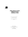
Figure 2-1 shows an example of a 1700 meter fiber link with a mechanical
splice using 62.5/125 fiber cable
.
Figure 2-1. 1700 Meter Fiber Link With Mechanical Splice
To calculate the maximum link distance:
1. Use Table 2-3 to determine the optical power budget for 62.5/125
cable (10.0 dB).
2. Use Table 2-6 to determine the worst case loss for a mechanical splice
(1.0 dB).
2 - 12 ONline Ethernet 10BASE-FB Module Installation and Operation Guide
3. Use Table 2-7 to determine the worst case loss for the 62.5/125 fiber
cable (1700 meters x 5 dB = 8.5 dB). Add the losses to determine
total path loss. The total path loss is 9.5 dB. Because the overall
power budget is 10.0 dB, this leaves .5 dB to spare, so the link can be
made.
Ensure you do not overdrive a receiver (that is, the received optical power
level is not greater than the maximum received sensitivity level of the fiber
connector). In this case, the maximum possible transmit power (-17 dB +
3.0) is -14.0 dB (see Table 2-3). The power loss over the link is 9.5 dB. This
means that the power level of the signal will drop to -23.5 dB by the time it
reaches the receiver. Because the maximum receiver sensitivity is -8.0 dB,
there is no overdrive problem.
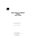
Example: 2000 Meter Fiber Link Through Two Patch Panels
In this example, two ONline concentrators are separated by 2000 meters of
fiber cable with two patch panels between them
.
Figure 2-2. 2000 Meter Fiber Link Through Two Patch Panels
To calculate the maximum link distance:
1. Use Table 2-3 to determine the optical power budget for 50/125
cable (5.5 dB).
2. Use Table 2-6 to determine the worst case loss for two ST patch
panels (1.5 dB).
Designing and Expanding the Network 2 - 13
3. Use Table 2-7 to determine the worst case loss for the 50/125 fiber
cable (2000 meters x 5 dB = 10.0 dB). Add the dB losses to
determine total path loss. The total path loss is 11.5 dB.
The 11.5 dB optical loss exceeds the optical power budget of 5.5 dB.
Therefore the link will not work and the 10BASE-FB Module Port
Status LED will signal a Low Light condition.
Thus, you must use High Power mode. When you use High power
(see Table 2-4), the optical power budget of 13.5 dB is sufficient to
handle the 11.5 dB path loss.
Choosing a Network Backbone Cabling Structure
Because of fiber's long-distance capabilities and immunity to noise, 3Com
strongly recommends using fiber as the backbone. You can choose
between two fundamental configuration topologies when connecting your
network backbone using 10BASE-FB Modules in an ONline System
Concentrator:
❑
Star Configuration
❑
Serial Configuration
2 - 14 ONline Ethernet 10BASE-FB Module Installation and Operation Guide
Star Configuration
Wire your network in a star configuration using an ONline System
Concentrator as the central point in the network. Wiring in a star topology
configuration has two major benefits:
❑
Faults in the cable plant affect only a piece of the network
❑
You can easily expand the size of your network.
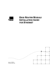
Figure 2-3 shows an example of a Star-wired configuration..
Figure 2-3. Star-Wiring Configuration
Designing and Expanding the Network 2 - 15
Serial Configuration
Use a serial configuration (shown in Figure 2-4) for smaller diameter
networks that are not expected to grow. Serial configurations reduce the
overall network diameter by 190 meters for each concentrator in any path)
.
Figure 2-4. Serial Configuration Using 10BASE-FB Modules
2 - 16 ONline Ethernet 10BASE-FB Module Installation and Operation Guide
10BASE-FB Module Configurations
The theoretical maximum diameter of an all fiber Ethernet network is
limited to 4.2 km as defined by the 51.2 µsec slottime that is specified for
the round trip delay budget set by the IEEE 802.3 CSMA/CD protocol.
(Thus, point-to-point link distances are limited to a maximum of 4.2 km.)
This section describes how to define total network size based on the limits
of IEEE 802.3 collision detection.
This section describes the following scenarios:
❑
Fiber Backbone, Fiber-to-the-Desk
❑
Fiber Backbone, Unshielded Twisted Pair-to-the-Desk
❑
Fiber Backbone, Coaxial Connection
Fiber Backbone, Fiber-to-the-Desk
When designing an all-fiber network (Figure 2-5), keep the following rules
in mind:
1. Limit the longest path from one fiber optic transceiver to another to
4.2 km (2.6 miles).
2. Each 10BASE-FB Module in a serial path between two transceivers
reduces the maximum cable distance between the transceivers by
190 meters (623 feet). The equivalence is:
❑
140 meters for signals that externally enter a 10BASE-FB Module
port
❑
50 meters for signals that internally enter a 10BASE-FB Module
from the concentrator backplane
For simplicity, use 190 meters per 10BASE-FB Module in the path when
calculating fiber equivalent distances.
Designing and Expanding the Network 2 - 17
3. AUI cables of up to 50 meters are not included in Rule number 1, thus
the total network diameter between fiber Ethernet nodes can be 4110
meters (4200 m - 190 m + 50 m + 50 m = 4110 m) through a single
concentrator
.
Figure 2-5. All-Fiber Network
The Ethernet four-repeater rule limits the number of repeaters between any
two transceivers to four. In general, this restricts most vendor
configurations to a maximum of four concentrators connected in series.
This restriction does not apply to the ONline System Concentrators when
using ONline 10BASE-FB Modules to connect concentrators. This is because
the 10BASE-FB Modules use a synchronous (repeaterless) technology.
2 - 18 ONline Ethernet 10BASE-FB Module Installation and Operation Guide
Network Distance Calculation Examples
The following examples demonstrate how to calculate network distances
for various all-fiber networks.
Example: Network With 3 Concentrators
Figure 2-6 shows a network with 3 concentrators.
Figure 2-6. Network With 3 Concentrators
To determine the maximum allowable link distance between Concentrators
A and C:
1. Use 4200 m as the maximum network diameter for a pure fiber
network as defined by the 802.3 specification. (Rule 3).
2. Subtract the fiber equivalent of the three concentrators with
10BASE-FB Modules that occur on the path between the two
transceivers:
3 * 190 meters = 570 meters (Rule 4)
Designing and Expanding the Network 2 - 19
3. Subtract the known amount of fiber cable between the two
transceivers:
1 km + 1 km + 1 km = 3 km (Rule 5)
4. The remainder is the maximum allowable distance of the link
between Concentrators A and C:
4200 m - 570 m - 3000 m = 630 meters
5. Verify that the optical power budget is able to drive all the link
distances in the example. Because all link distances are only 1 km or
less, this is not a problem.
Example:
Network with 8 Concentrators
Figure 2-7 shows a network with eight connected concentrators. Use this
example to determine if the distances between transceivers are all within
the 4200 meter maximum network diameter restriction for Ethernet
networks.
100m
500m
Conc A
1km
Conc E
Conc C
Transceivers
500m
500m
Conc D
Transceivers
100m
500m
Conc E
400m
Conc F
Conc G
100m
1km
Transceivers
Conc H
100m
Note: All transceiver connections to concentrators are 100 meters
Figure 2-7. Network Configured With 8 Concentrators
2 - 20 ONline Ethernet 10BASE-FB Module Installation and Operation Guide
In this example, the path between transceivers attached to Concentrators A
and G has the greatest fiber equivalent distance (4240 meters), even
though the link distance is less than the A to H path (3100 meters versus
3200 meters). Because 4240 meters exceeds the 4200 meter maximum,
this configuration is illegal and results in improper network operation.
Because it is not always obvious which path between transceivers has the
highest fiber equivalent distance, use Table 2-8 to help you determine the
equivalent distances.
Table 2-8. Fiber Equivalent Distances Between Transceivers
Path
Total Fiber
Link
Distance
Between
Transceivers
(meters)
A-D
2700
5
950
3650
A-H
3200
5
950
4150
A-G
3100
6
1140
4240
D-H
1700
3
570
2270
D-G
1600
4
760
2360
G-H
2100
4
760
2860
Number of
Concentrators
Between
Transceivers
Equivalent
Fiber Distance
of
Concentrators
(meters)
Total
Fiber
Equivalent
Distance
(meters)
Designing and Expanding the Network 2 - 21
Fiber Backbone, Unshielded Twisted Pair to-the-Desk
Configuring a network with unshielded twisted pair cabling to-the-desk is
similar to an all-fiber network because the cabling is star-wired in both
cases.
Be aware of the following additional rules for configuring a network:
❑
The four-repeater rule in Ethernet limits the number of 10BASE-T
modules between any two transceivers. The path from the TP port to
the backplane counts as 1/2 of a repeater and the path from the
backplane to the TP port counts as 1/2 of a repeater. You must add
a bridge if the path from one transceiver to another exceeds the
four-repeater rule.
❑
The equivalent fiber distance for the 10BASE-T Modules is defined in
“Understanding Network Configuration” in this chapter:
–
420 meters for signals that externally enter a 10BASE-T
Module port
–
165 meters for signals that internally enter a 10BASE-T
Module through the ONline concentrator backplane
For each pair of 10BASE-T Modules that a signal goes through, there is a
fiber equivalent distance of 585 meters (420 m + 165 m =585 m). In
addition, if a signal makes a roundtrip through a 10BASE-T Module, (that is,
enters a 10BASE-T port externally and exits through another port on the
same 10BASE-T Module) that counts as 585 meters of fiber equivalent
distance, and as a full repeater.
Example: Sample Configuration Distance Calculation
Use the following example to determine if the 10BASE-T Transceivers in
Figure are within legal Ethernet limits. Identify the two transceivers that
are likely to be the greatest fiber equivalent apart in Figure 2-8. In this
case, they are 10BASE-T Transceivers A and B.
2 - 22 ONline Ethernet 10BASE-FB Module Installation and Operation Guide
Figure 2-8. Sample Configuration Distance Calculation
To determine if your network configuration is legal:
1. Use 4200 m as the maximum network diameter for a pure fiber
network as defined by the 802.3 specification.
2. Calculate the equivalent distances for each concentrator, and
subtract the total from 4200 (see figures for details).
3. Subtract all cable lengths between the two transceivers and if the
result is greater than zero, the configuration is within legal Ethernet
limits (Rule 5).
For the configuration shown in Figure 2-8 to work, ensure the fiber
equivalent distance between Transceiver A and Transceiver B is less than
4200 meters. As shown in the calculation, there are still 1510 meters left for
expansion in this configuration. Therefore, this configuration is legal.
Designing and Expanding the Network 2 - 23
Fiber Backbone, Coaxial Connection
When connecting Thick or Thin Ethernet segments to an ONline network,
use an:
❑
ONline Ethernet Bridge Module
❑
ONline Ethernet Repeater Module
❑
External bridge or repeater
If you use a repeater or the ONline Ethernet Repeater Module, remember
that these products have an equivalent fiber distance of 800 meters.
Example: Connecting a Thin Ethernet (10BASE2) Segment
Figure 2-9 shows an example of a Thin Ethernet segment connected to an
ONline System Concentrator using an IEEE Repeater
.
Figure 2-9. Thin Ethernet Segment Connected to an ONline
10BASE-FB Module
2 - 24 ONline Ethernet 10BASE-FB Module Installation and Operation Guide
To determine if the configuration meets Ethernet distance limitations for
Transceivers A and B:
1. Use 4200 m as the maximum network diameter for a pure fiber
network as defined by the 802.3 specification (Rule 3).
2. Subtract the fiber equivalent distance of 420 m for the signal entering
the 10BASE-T Module from Transceiver B and 50 meters for the signal
exiting the 10BASE-FB Module within the same concentrator (Rule 4).
3. Subtract the fiber equivalent distance of 190 m for the signal
entering the 10BASE-FB Module in the top concentrator, and exiting a
different port on the same 10BASE-FB Module.
4. Subtract the fiber equivalent distance (800 m) of the IEEE Repeater
(Rule 4).
Note: In the reverse direction, a signal originating at Transceiver
A loses 165 m of fiber equivalent distance when it exits the
10BASE-T Module to which Transceiver B is connected and
140 meters for the signal entering the 10BASE-FB Module in
the lower concentrator. Because the overall fiber
equivalence of the path is greater for signals going from
Transceiver B to A, the fiber equivalence of this path
determines whether the link meets the 4200 m Ethernet
link maximum.
5. Subtract the sum of intervening cable lengths:
150 m + 50 m + 200 m + 2000 m + 100 m = 2500 m
6. The remainder is 4200 m - 420 m - 50 m - 190 m - 800 m - 2500 m =
240 m.
Designing and Expanding the Network 2 - 25
Fault-Tolerant Configurations
This section contains descriptions of the redundancy features built into the
ONline 10BASE-FB Modules. You can implement link redundancy between
concentrators using the port redundancy switch settings on the 10BASE-FB
Modules or through ONline network management.
This section contains the following topics:
❑
Configuring Ports for Fault Tolerance
❑
Implementing Total Backbone Fault Tolerance
Configuring Ports for Fault Tolerance
You can configure the 10BASE-FB Module ports in one of four different
ways:
❑
Normal Configuration – Ports 1 through 4 operate as independent
cable ports.
❑
Standard Redundant Configuration – In this configuration:
–
Port 1 acts as the primary port and port 2 as the backup
for 1
–
Port 3 acts as the primary port and port 4 as the backup
for 3
❑
Flexible Redundant Configuration – You can arbitrarily assign
primary and backup ports to any pair of ports. You can configure
this mode only through the advanced management commands
provided with EMM V3.0 or greater.
❑
Normal and Redundant Configuration – You can enable
redundancy between one set of ports and have the remaining two
ports operate as independent ports.
2 - 26 ONline Ethernet 10BASE-FB Module Installation and Operation Guide
Setting Redundancy
When you enable redundancy between two ports, the ports are
automatically enabled.
❑
Port 1 (or 3) as the primary link, which passes data.
❑
Port 2 (or 4) as the redundant link, which does not pass data in either
direction. However, the link is monitored for any failures (the Port
Status LED indicates any problems).
For maximum cable plant fault tolerance, connect both the primary and
backup ports back to the central concentrator (Figure 2-10). This
configuration allows the backup port to automatically take over if the
primary link fails
Designing and Expanding the Network 2 - 27
.
Figure 2-10. Redundant Fiber Backbone Configuration
Note: Always enable redundancy in the lower level concentrators
(those connecting to the central concentrators in the
star-wired topology).
In any redundant link path, only one end can be designated (that is,
activated) as a redundant port pair (ports 1 and 2 or ports 3 and 4). If you
enable 10BASE-FB Module ports at both ends as redundant, improper
operation of the redundant switchover mechanism occurs (see Figure 2-11).
2 - 28 ONline Ethernet 10BASE-FB Module Installation and Operation Guide
If the primary link experiences a local or remote fault (except Low Light):
❑
The backup link activates within 10 milliseconds
❑
The primary ports disconnect (that is, they do not pass data to and
from the concentrator)
However, primary port diagnostics continue to operate. When the fault
clears, the primary port is enabled automatically. Once a switchover occurs,
the redundancy status indicators blink.
Each redundancy status LED (located beneath the Activity LEDs):
❑
Is off - If you disable redundancy
❑
Is on - If you enable redundancy and both ports are operational
❑
Blinks - If a switchover occurs due to a link failure
Implementing Total Backbone Fault Tolerance
You can add a backup ONline System Concentrator to provide total
backbone tolerance and link redundancy for your backbone network. As
shown in Figure 2-11, if the primary concentrator or any primary links fail,
the backup concentrator takes over. In this configuration:
❑
One port on the 10BASE-FB Module connects to the primary
concentrator
❑
The other port connects to the backup concentrator
You must also have a direct connection between the two concentrators.
Designing and Expanding the Network 2 - 29
.
Figure 2-11. Total Backbone Fault-Tolerant Configuration
Example: Fiber Network with 3 Concentrators and a Fourth
Concentrator in Full Redundancy Configuration
In Figure 2-12, three concentrators are active where Concentrator B is a
redundant concentrator for Concentrator A.
2 - 30 ONline Ethernet 10BASE-FB Module Installation and Operation Guide
.
Figure 2-12. Fiber Network With 3 Concentrators
In Figure 2-12, the fiber equivalent distance between transceivers attached
to Concentrators C and D is:
3 * 190 m + 1000 m + 1000 m + 500 m + 1000 m = 4070 m
Because this is less than 4200 meters, the configuration is legal.
In Figure 2-12, if the main link from Concentrator A to Concentrator C
faults, the signal path (enabled through redundancy) includes Concentrator
B. By adding Concentrator B, the fiber equivalent distance has become too
great and the network cannot work because the path between
Concentrators C and D is C-B-A-D:
4 * 190 + 1000 m + 2000 m + 500 m + 500 m + 1000 m = 5760 m
Because the sum is greater than 4200 meters, this configuration is not
legal. When designing a redundant network, be sure to consider the
backup route distance.
Designing and Expanding the Network 2 - 31
3
Installing and
Operating the Module
This chapter describes the installation procedures for the:
❑
ONline Ethernet Port-Switching 10BASE-FB Module
❑
ONline Ethernet 10BASE-FB Module
For your convenience, a quick reference installation chart is included. This
chapter includes the following sections:
❑
Precautionary Procedures
❑
Unpacking Procedures
❑
Quick Installation
❑
Setting the Dip Switches
❑
Installing the Module
❑
Configuring the Module
❑
Showing Module Configuration
❑
Monitoring the Front Panel
❑
Verifying the LEDs and Network Assignments
Installing and Operating the Module 3 - 1
Note: Read the precautionary procedures before unpacking the
module.
Precautionary Procedures
Electrostatic discharge (ESD) can damage static-sensitive devices on circuit
boards. Follow these precautions when you handle the 10BASE-FB
Modules:
❑
Do not remove the board from its anti-static shielding bag until you
are ready to inspect it.
❑
Handle the board by the faceplate.
❑
Use proper grounding techniques when you install a 10BASE-FB
Module. These techniques include:
–
Using a foot strap and grounded mat or wearing a
grounded static discharge wrist strap.
–
Touching the grounded rack or other source of ground
just before you handle a 10BASE-FB Module.
3 - 2 ONline Ethernet 10BASE-FB Module Installation and Operation Guide
Unpacking Procedures
When unpacking your 10BASE-FB Module:
1. Verify that the 10BASE-FB Module is the correct model by matching
the model number listed on the side of the shipping carton to the
model number you ordered (Model Numbers 5102M-FBP, 5104M-FBP,
or 5104M-FB1).
Note that the product model number printed on the shipping box
differs from the model number on the product. The model number
on the shipping box contains the prefix ’3C9’.
2. Remove the module from the shipping carton.
3. Remove the module from the anti-static shielding bag and inspect it
for damage. If the module appears to be damaged, replace it in the
anti-static shielding bag, return it to the shipping carton, and contact
your local supplier.
4. Keep the shipping carton and anti-static shielding bag in which your
module was shipped for repackaging the module for storage or
shipment.
5. Record the serial number of your 10BASE-FB Module. A log for this
and other information specific to your modules is included in the
ONline SystemConcentrator Installation and Operation Guide,
Appendix B, Slot Usage Chart.
Installing and Operating the Module 3 - 3
Quick Installation
Table 3-1 outlines the steps for installing your 10BASE-FB Module.
Table 3-1. Quick Installation Procedures
Step
Procedure
Section Title
1
Verify that your network complies with
the basic rules for network design.
Chapter 2,
Designing and
Expanding the
Network
2
Unpack the module.
Unpacking
Procedures
3
If you do not have a management module
installed in the concentrator, configure the
dip switch settings to your specifications.
Setting the Dip
Switches
4
Insert the module into a blank slot in the
concentrator and tighten the faceplate
screws.
Installing the
Module
5
Establish connections from the 10BASE-FB
Module to another 10BASE-FB Module or
10BASE-FB Transceiver using the
appropriate connectors and cabling.
Installing the
Module
6
If you have a management module
installed in the concentrator, configure the
module using the management
commands.
Configuring the
Module
7
Verify LED status for normal operation.
Note: To correct problems, consult the
troubleshooting techniques in Chapter 4.
Verifying LED and
Network
Assignments
3 - 4 ONline Ethernet 10BASE-FB Module Installation and Operation Guide
Setting the Dip Switches
The 10BASE-FB Modules have two 10-position dip switches (S1 and S2)
located on the board. Figure 3-1 shows the dip switches on the 10BASE-FB
Modules and the factory settings.
❑
Dip switch S1 on the Port-Switching Module differs from dip switch
S1 on the Module-Switching Module. Figure 3-1 contains examples
of both dip switches.
❑
Dip switch S2 is identical for both the Port-Switching Module and
Module-Switching Module except the Module-Switching Module does
not provide High power optics.
You may need to reconfigure one or more of these switches depending on
your configuration requirements.
The dip switch settings for the 10BASE-FB Modules are ignored if an ONline
management module is installed in the concentrator. For this reason, use
the management commands (rather than the dip switches) to configure
the 10BASE-FB Modules. If you have an installed management module,
install the 10BASE-FB Module first and then refer to the Configuring the
Module section in this chapter for more information.
This section describes:
❑
Setting Dip Switch S1
❑
Setting Dip Switch S2
Installing and Operating the Module 3 - 5
Figure 3-1. 10BASE-FB Module Dip Switch Locations
Note: The Port-Switching 10BASE-FB Module is also available as a
two-port module (Model Number 5102M-FBP) for
installations that do not require four fiber ports. When
using the switches for the two-port module, all switches
operate identical to the switches on the four-port module
with the exception of port 3 and port 4 switches. These
switches do not perform any operation.
3 - 6 ONline Ethernet 10BASE-FB Module Installation and Operation Guide
Setting Dip Switch S1
The S1 dip switch on the 10BASE-FB Modules have 10 switches. These
switches allow you to enable or disable redundancy between ports 1 & 2
and 3 & 4.
The S1 dip switch on the:
❑
Port-Switching 10BASE-FB Module allows you to - assign each port to
a backplane channel
❑
Module-Switching 10BASE-FB Module allows you to - assign the
module to a backplane channel
For a definition of each dip switch function, refer to the Configuring the
Module section.
Table 3-2 lists the functions and settings for switches 1 and 2.
Table 3-2. Dip Switch S1 Settings for Switches 1 and 2
Function
Factory
Default
Switch Setting
Off
On
Switch
Label
1
REDN12
Enable/disable
redundancy
between ports 1
and 2
disable
disable
enable
2
REDN34
Enable/disable
redundancy
between ports 3
and 4
disable
disable
enable
Installing and Operating the Module 3 - 7
Table 3-3 lists the functions and settings for switches 3 through 10.
Table 3-3. Dip Switch S1 Settings for Switches 3 to 10
Switch Setting
CHA0
CHA1
Channel Selection
On
On
1 (factory default)
Off
On
2
On
Off
3
Off
Off
Isolated
Port-Switching Module: Port
operates independent of any
backplane channel.
Module-Switching Module:
Module operates independent of
any backplane channel.
3 - 8 ONline Ethernet 10BASE-FB Module Installation and Operation Guide
Setting Dip Switch S2
Dip switch S2 on the 10BASE-FB Modules have 10 switches. These switches
allow you to:
❑
Enable high or normal optical power for each port
❑
Enable or disable any of the four ports
❑
Enable or disable low light detection for the module
Table 3-4 lists the functions and settings for dip switch S2. Switch 10 is not
used.
Table 3-4. Dip Switch S2 Settings
Function
Factory
Default
Switch Setting
Off
On
Switch
Label
1
P1 HIPWR
Port 1 High or
Normal power
disable
(normal)
disable
enable
2
P2 HIPWR
Port 2 High or
Normal power
disable
(normal)
disable
enable
3
P3 HIPWR
Port 3 High or
Normal power
disable
(normal)
disable
enable
4
P4 HIPWR
Port 4 High or
Normal power
disable
(normal)
disable
enable
5
P1 EN
Enable/disable
Port 1
enable
disable
enable
6
P2 EN
Enable/disable
Port 2
enable
disable
enable
7
P3 EN
Enable/disable
Port 3
enable
disable
enable
8
P4 EN
Enable/disable
Port 4
enable
disable
enable
Installing and Operating the Module 3 - 9
Table 3-4. Dip Switch S2 Settings (Continued)
Switch
Label
9
LOL EN
10
Not Used
Function
Enable/disable
module Low
Light Detection
Factory
Default
enable
Switch Setting
Off
On
disable
enable
Installing the Module
You do not need to power down the ONline System Concentrator to install
the 10BASE-FB Modules. You can insert or remove the module while the
concentrator is operating (this is called a hot swap).
To install a 10BASE-FB Module:
1. Do one of the following:
❑
If you do not have a management module installed in the
concentrator, set the dip switches on the board (if different from
the default setting). After you complete the installation
procedure, go to the Monitoring the Front Panel section to verify
the installation.
❑
If you have a management module installed in the concentrator,
complete this installation procedure and then configure the
module using the commands as described in the Configuring the
Module section.
2. Locate a blank slot in the concentrator. If there is no blank slot,
remove a blank panel on the concentrator to expose a slot for a
10BASE-FB Module.
3 - 10 ONline Ethernet 10BASE-FB Module Installation and Operation Guide
3. Insert the module into the board guides at the top and bottom of the
slot and slide it into the concentrator. Make sure that the connector
is well-seated into the backplane of the concentrator.
Figure 3-2 shows the installation of a 10BASE-FB Module
.
Figure 3-2. Installing the 10BASE-FB Module
4. Fasten the spring-loaded screws on the front of the 10BASE-FB
Module faceplate to the concentrator using your fingers (do not
overtighten).
5. Remove the plastic fiber optic covers from the cable ports. Keep
unused cable ports capped to keep the optics clean.
6. Attach the fiber cables to the fiber ports on the front of the
10BASE-FB Module as shown in Figure 3-3.
Installing and Operating the Module 3 - 11
.
Figure 3-3. 10BASE-FB Module Connection
7. Make sure transmit and receive cables are:
❑
Clearly marked or color-coded.
❑
Connected to the appropriate ports on the 10BASE-FB Module.
❑
Properly cleaned with an appropriate fiber optic cleaning solution
before installation.
Note: Do not exceed the bend radius for the fiber cable when
directing the cables under the concentrator. Refer to the
cable manufacturer's specifications for minimum bend
radius.
8. Attach the other ends of the cables to either:
❑
Another 10BASE-FB module
❑
3Com 10BASE-FB Star Coupler port
❑
3Com 10BASE-FB Transceiver
3 - 12 ONline Ethernet 10BASE-FB Module Installation and Operation Guide
❑
3Com Fault-Tolerant 10BASE-FB Transceiver
Make sure that the transmit fiber at one end always connects to a
receive port at the other end.
Caution:
Do not connect this module to an ONline 10BASE-FL
Module or to any other product that is not compatible
with the 10BASE-FB modules. These illegal connections
may cause network failure.
Configuring the Module
The ONline management modules can configure the following settings on
the 10BASE-FB Modules:
❑
Enable and disable each port on the module
❑
Set the ports to independent Ethernet networks within the
concentrator (Port-Switching 10BASE-FB Module)
❑
Set the module to independent Ethernet networks within the
concentrator (10BASE-FB Module)
❑
Set redundancy between two ports on the module or between ports
on another 10BASE-FB Module (using Advanced EMM V4.01 or
higher)
❑
Enable and disable the low light warning
❑
Set the fiber optic transmission power for each port
The following ONline management modules provide network management
capabilities for the ONline System Concentrator and its modules:
❑
Ethernet Management Module V4.01
❑
Token Ring Management Module V3.10
❑
FDDI Management Module V2.00
Installing and Operating the Module 3 - 13
When an ONline management module is installed in a concentrator, all of
the dip switch settings on the 10BASE-FL Module are overridden.
When you first install the module:
1. The network (channel) defaults to isolated mode. The ports are
automatically disabled so that unapproved users cannot be added.
Therefore, you must enable the ports you wish to use and set the
ports to the appropriate Ethernet network through the management
commands.
2. All other module settings retain the same default values as the dip
switch default values. Therefore, you only need to changes these
values through management if you do not want the default values.
This section describes the management commands to set these features.
For additional information on the available network management features,
refer to:
❑
The appropriate ONline management module installation and
operation guide
❑
ONline Management Commands Guide
Enabling Ports
You can enable or disable each of the four ports on the module. When a
port is enabled, it can transmit data onto and receive data from the
network to which the module is assigned. Disable all unused ports on the
10BASE-FB Modules to prevent the Status indicators from flashing a No
Light condition.
To enable or disable a specific port, use the following management
command:
SET PORT
{slot.port} MODE
{slot.all}
{enable}
{disable}
3 - 14 ONline Ethernet 10BASE-FB Module Installation and Operation Guide
Selecting a Network
Both models of the Port-Switching Module (Model Numbers 5102M-FBP or
5104M-FBP) support Port-Switching technology. This feature enables you to
assign each port on the module to any of three Ethernet networks (or
isolated) on the ONline System Concentrator backplane.
To set a port to a network or to isolated mode, use the following
management command:
SET PORT
{slot.port}
{slot.all}
NETWORK
{ethernet_1}
{ethernet_2}
{ethernet_3}
{isolated}
The 10BASE-FB Module (Model Number 5104M-FB) enables you to assign
the module to any of the three Ethernet networks (or isolated) on the
ONline System Concentrator backplane.
To set a module to a network or to isolated mode, use the following
management command:
SET MODULE
{slot}
NETWORK
{ethernet_1}
{ethernet_2}
{ethernet_3}
{isolated}
Note: The dip switch settings on the module refer to the
backplane connection as the “channel” connection. The
channel setting and the network setting are the same.
Modules or ports set to the same network communicate
with each other.
Installing and Operating the Module 3 - 15
Enabling Port Redundancy
You can enable port redundancy in one of the following ways:
❑
If you have network management, you can enable or disable main
port redundancy between any two ports on the 10BASE-FB Module.
❑
If you do not have management, you can use the dip switches on the
module to configure redundancy between ports 1 and 2 on the
module or ports 3 and 4.
For example, when you enable redundancy:
1. Port 1 becomes the primary link and port 2 is the redundant link.
2. If the primary link (port 1) fails, the redundant link (port 2) is engaged
automatically, thus preventing a network failure.
3. When you disable redundancy, each port works independently.
Note: Enabling port redundancy for two ports automatically
enables the ports, even if the ports were previously
disabled.
The redundancy status LEDs, located between the sets of port LEDs and the
port connectors on the 10BASE-FB Module, are:
❑
Off - When you disable redundancy (default setting)
❑
On - When you enable redundancy
To set redundancy between ports, use the following management
command:
SET PORT {slot.port} MODE REDUNDANT {slot.port}
To turn off redundancy between ports, use the MODE NON_REDUNDANT
option. Redundancy configurations are shown in Chapter 2, Designing and
Expanding the Network.
3 - 16 ONline Ethernet 10BASE-FB Module Installation and Operation Guide
When you set redundancy between two ports on the same 10BASE-FB
Module and the primary port and the redundant port experience a link
failure simultaneously, and you disable redundancy:
❑
The primary port is disabled
❑
The redundant port is enabled
Enabling Low Light Warning
You can enable or disable low light warning for all ports on the module.
When you enable low light warning, the Status LED of the port which
detects the low light condition blinks 6 times. (A low light condition is
defined as power received between -26.0 dBm and -30.0 dBm peak power.)
You may have a legal configuration in which low light is acceptable to span
a long distance. In this case, you may want to disable the low light
warning so the Status LED does not blink for this connection.
To enable or disable low light warning for a port, use the following
management command:
SET PORT
{slot.port} LOW_LIGHT_WARNING {enable}
{slot.all}
{disable}
Enabling Optical Power
High-power optics are standard in all 3Com ONline fiber optic products.
The higher power allows you to directly connect buildings as far as 4.0
kilometers apart without the additional expense of signal-boosting
equipment. However, it is necessary to set a port to the normal power
setting when it is connected to a 3Com 10BASE-FB fiber optic product.
Each port on the Port-Switching 10BASE-FB module can be set to high or
normal power through the dip switches or through management
commands. To set a port to high or normal power, use the following
management command:
SET PORT
{slot.port} HIGH_POWER
{slot.all}
{enable}
{disable}
Installing and Operating the Module 3 - 17
The 10BASE-FB Module-Switching Module can be set to high or normal
power through the dip switches (see Table 3-4).
Saving Module Configuration
To save the module and port settings to management module memory, use
the following command:
SAVE MODULE_PORT
Showing Module Configuration
You can display status information about the 10BASE-FB Modules using the
following commands:
❑
SHOW MODULE
❑
SHOW MODULE VERBOSE
❑
SHOW PORT
❑
SHOW PORT VERBOSE
For example, the following command displays detailed information about
port 1 on the Port-Switching 10BASE-FB Module in slot 8 of the
concentrator.
ONline> show port 8.1 verbose
[ENTER]
Port Display for Module 5104M-FBP:
Port
Mode
Status
Network
General Information
_____________________________________________________________
08.01
ENABLED
OKAY
Network Dip Setting:
Mode Dip Setting:
Low Light Warning:
Low Light Warning Dip Setting:
High Power Optics:
High Power Optics Dip Setting:
ETHERNET_2
ETHERNET_2
ENABLED
ENABLED
ENABLED
ENABLED
DISABLED
3 - 18 ONline Ethernet 10BASE-FB Module Installation and Operation Guide
This display tells you the status of the specific port. It includes the
management and dip switch settings from the board.
The following command displays detailed information about the 10BASE-FB
Module in slot 8 of the concentrator.
ONline> show module 8 verbose
[ENTER]
Port Display for Module 5104M-FB1:
Slot
Module
08
5104M-FB1
Version
00x
Network
ISOLATED
General Information
ETHERNET_2
5104M-FB1: ONline Ethernet 10BASE-FB Module
Network Dip Setting:
Low Light Warning:
Low Light Warning Dip Setting:
ETHERNET_1
DISABLED
DISABLED
This display tells you the status of the specific module. It includes the
management and dip switch settings from the board.
For more information on the SHOW commands, refer to the:
❑
Appropriate ONline management module installation and operation
guide
❑
ONline Management Commands Guide
Monitoring the Front Panel
The LEDs on the front panel of the 10BASE-FB Module allow you to monitor
the status of each port. The 10BASE-FB Module has 10 LEDs on the front
panel that allow you to monitor diagnostic, activity, and redundancy status
for each port. Figure 3-4 shows the locations of these indicators.
Installing and Operating the Module 3 - 19
Figure 3-4. 10BASE-FB Port-Switching Module Faceplate and
ONline System Concentrator
3 - 20 ONline Ethernet 10BASE-FB Module Installation and Operation Guide
Table 3-5 describes how to interpret the 10BASE-FB Module LEDs.
Table 3-5. Interpreting the 10BASE-FB Module LEDs
LED Name
Activity
Color
yellow
(Ports 1-4)
Status
green
(Ports 1-4)
Redundancy
(Ports 1-2)
(Ports 3-4)
green
State
Indicates
Off
No packets are received on the
fiber segment.
On
Constant activity on the fiber
segment.
Blinking
Module receives packets from
segment to which it is attached.
Off
Port disabled.
On
Port enabled or in standby and link
integrity is OK.
1 blink
No light detected.
2 blinks
Jabber.
3 blinks
Partition.
4 blinks
Remote fault.
5 blinks
Invalid data received.
6 blinks
Low light received (you can disable
it using Low Light switch setting).
Off
Redundancy is disabled; ports are
independent of each other.
On
Redundancy is enabled between
ports 1 & 2 and 3 & 4.
Blinking
Switchover has taken place or there
has been a link failure.
Installing and Operating the Module 3 - 21
Verifying LED and Network Assignments
Once you install the module, verify its operation through the front panel of
the ONline Controller Module. The Controller Module is equipped with an
LED check button on the front panel. Use the LED check buttonto:
❑
Verify LED operation
❑
Verify network (channel) assignment
When you press this button, the Controller Module initiates a test to all
modules in the concentrator. All LEDs should respond by lighting
continuously for approximately five seconds. Any LED that does not light is
defective.
After the 5 seconds elapse, the diagnostic continues with a network
(channel) check of all modules. Each Status LED should respond by blinking
the number of times to correspond with the network to which the module
is assigned. The network check sequence repeats 5 times. Table 3-6
explains the network check codes.
Table 3-6. Network Check Codes
LED State
Network Configuration
1 Blink
Module or port is configured for network 1
2 Blinks
Module or port is configured for network 2
3 Blinks
Module orport is configured for network 3
Off
Module or port is isolated (operates independent of any
network)
4
Troubleshooting
This chapter describes fault conditions and troubleshooting procedures for
the ONline Ethernet 10BASE-FB Modules.
This chapter contains the following sections:
❑
Troubleshooting Using the Port Activity LEDs
❑
Troubleshooting Using the Port Status LEDs
❑
Technical Assistance
Troubleshooting 4 - 1
Troubleshooting Using the Port Activity LEDs
If a port Activity LED does not light, use Table 4-1 to help troubleshoot the
problem.
Table 4-1. Troubleshooting Using the Port Activity LEDs
LED
State
Off
Possible Cause
Corrective Action
There is no traffic received
from the segment.
None.
Port is disabled.
Use the EMM to check if the
port is enabled or check the port
dip switch setting.
Power is off.
Check the Controller Module
Power LEDs.
Activity LED has burned
out.
Press the LED check button on
the Controller Module.
10BASE-FB Module port is
faulty.
Connect the cable to a different
port.
10BASE-FB Module is
faulty.
Try a different 10BASE-FB
Module.
Backplane connection is
bad.
Reinsert the 10BASE-FB
Module. If this fails, try another
concentrator slot.
4 - 2 ONline Ethernet 10BASE-FB Module Installation and Operation Guide
Troubleshooting Using the Port Status LEDs
A blinking Port Status indicator is always a sign that the port detects a
potential problem. Once a port detects a problem, you can further analyze
the problem by counting the number of blinks. Table 4-2 provides
troubleshooting suggestions for each of the blinking sequences.
Table 4-2. Troubleshooting Using the Port Status LEDs
LED State
Off
Indication
Port Disabled
Possible Cause
Corrective Action
Port disabled.
Enable port.
10BASE-FB
Module not
powered up.
Check concentrator
power status.
Broken LED.
Press the LED check
button on Controller
Module.
Bad 10BASE-FB
Module.
Replace module.
Reinsert the
10BASE-FB Module.
Troubleshooting 4 - 3
Table 4-2. Troubleshooting Using the Port Status LEDs (Continued)
LED State
1 Blink
Indication
No Light
Received
Possible Cause
Corrective Action
Cables crossed.
Verify TX on remote
device is connected to
RX on 10BASE-FB
Module.
Insufficient
optical power
received.
Check 10BASE-FB
Module optical power
using a light meter.
Try High power on
remote device.
Check optical power of
remote device.
If optical power levels
are OK, check cable; it
may be bad or too
long.
Broken fiber
cable.
Check and fix RX fiber
link.
Bad fiber
connections.
Clean and reconnect
fiber (both ends).
Bad remote
device or port.
Replace remote device
or try another port.
Bad 10BASE-FB
Module.
Replace module.
4 - 4 ONline Ethernet 10BASE-FB Module Installation and Operation Guide
Table 4-2. Troubleshooting Using the Port Status LEDs (Continued)
LED State
2 Blinks
Indication
Jabber
Possible Cause
Corrective Action
Loop in network.
Disconnect each link
in the network one at
a time to isolate the
loop.
Bad 10BASE-FB
Module.
Replace module.
3 Blinks
Partition
Looped fiber
cable.
Remove looped cable.
4 Blinks
Remote Fault
Remote device
detects a
problem.
Check remote device's
status LEDs to identify
problem.
Bad remote
device.
Try another port or
replace device.
Bad 10BASE-FB
Module.
Replace the module.
Troubleshooting 4 - 5
Table 4-2. Troubleshooting Using the Port Status LEDs (Continued)
LED State
5 Blinks
6 Blinks
Indication
Invalid Data
Low Light
Received
Possible Cause
Corrective Action
Receive light
intensity too
high.
Verify that received
optical power level is
correct. Refer to
Chapter 2 (Link
Distances).
Connection
made to
10BASE-FL
Module.
Unplug the
connection. 10BASE-FL
is not compatible with
this 10BASE-FB
Module.
Bad fiber
connections.
Clean and reconnect
fiber (both ends).
Broken or
cracked fiber.
Check and fix RX fiber
link.
Bad remote
device.
Try another port or
replace device.
Bad 10BASE-FB
Module.
Replace the module.
Low light
received.
Verify optical power
received is at low end
of optical power
budget by doing an
optical power
calculation. If value is
acceptable, disable low
light detection.
Legal
configuration
with acceptable
low light.
Disable low light
detection or enable
High power at remote
end.
4 - 6 ONline Ethernet 10BASE-FB Module Installation and Operation Guide
Technical Assistance
You can receive assistance for installing and troubleshooting the 10BASE-FB
Module by calling either your 3Com reseller or 3Com Technical Support. Be
prepared to supply a representative with the following information:
❑
Description of the problem
❑
Steps you have taken to try and correct the problem
❑
Type and software version of the ONline network management
module being used
❑
Version of software installed on your 10BASE-FB Module
❑
Status of the front panel LEDs
❑
Configuration of your concentrator
(you may find it helpful to refer to the Slot Usage Chart in Appendix B
of the ONline System Concentrator Installation and Operation Guide
for a record of this information)
Refer to Appendix B for instructions on contacting Technical Support for
your product.
Troubleshooting 4 - 7
A
Specifications
This appendix lists specifications for the Port-Switching 10BASE-FB Module
and the 10BASE-FB Module. Specification differences between the
Port-Switching 10BASE-FB Module and the 10BASE-FB Module are indicated.
Specifications for the modules include:
❑
General Specifications
❑
Optical Specifications
❑
Power Specifications
❑
Environmental Specifications
❑
Mechanical Specifications
❑
Miscellaneous Specifications
❑
3Com 10BASE-FB Network Products
❑
10BASE-FB Cables and Connectors Specifications
Specifications A - 1
General Specifications
Table A-1 lists general specifications for the 10BASE-FB Module.
Table A-1. General Specifications
10BASE-FB Module Model Numbers
5102M-FBP
5104M-FBP
5104M-FB1
Collision Detection
100% deterministic
Configuration Rules
Compliant with IEEE 802.3
10BASE-FB specifications
Jabber Protection
10.8 ± 1 msec
Maximum Number of Nodes
1024
Backplane Interface
96-pin edge connector,
compatible with the ONline
System Concentrator
External Connector
4 pairs of fiber ports (ST, SMA, or
FC connectors)
Host Interface
ONline System Concentrator bus
interface standard
Installation Attachment
Two thumbscrews on the
mounting bracket
A - 2 ONline Ethernet 10BASE-FB Module Installation and Operation Guide
Optical Specifications
This section lists the optical specifications for the 10BASE-FB Module,
including:
❑
Transmitter Specifications
❑
Receiver Specifications
❑
Supported Fiber Optic Cables
❑
Fiber Optic Interface
Transmitter Specifications
Light Source: GaA1As LED at wavelength 820 ± 20 nm. Power coupled into
fiber cable inclusive of ST, SMA, or FC connector loss.
Table A-2 lists normal and high power transmit specifications.
Table A-2. Transmit Power
Cable Type
Normal Power
High Power
100/140 micron,
0.29 NA fiber
- 11.5 dBm (± 3.0 dBm)
- 4.5 dBm (± 2.25 dBm)
85/125 micron,
0.29 NA fiber
- 14.0 dBm (± 3.0 dBm)
- 7.0 dBm (± 2.25 dBm)
62.5/125 micron,
0.275 NA fiber
- 17.0 dBm (± 3.0 dBm)
- 10.0 dBm (± 2.25 dBm)
50/125 micron,
0.20 NA fiber
- 21.5 dBm (± 3.0 dBm)
- 14.25 dBm (± 2.25 dBm)
Specifications A - 3
Receiver Specifications
Table A-3 lists receiver specifications for the 10BASE-FB Module.
Table A-3. Receiver Specifications
Light Detector
Silicon PIN photodiode
Input Range
Optical power input of -8.0 dBm to -30.0 dBm
Bit Error Rate
1 in 10-10 over dynamic range
Dynamic Range
22.0 dB
Supported Fiber Optic Cables
You can use the following fiber optic cables with the 10BASE-FB Module:
❑
50/125
❑
62.5/125
❑
85/125
❑
100/140
The fiber optic cable must be:
❑
Micron diameter graded index
❑
Duplex fiber
❑
150 MHz km rating or better
A - 4 ONline Ethernet 10BASE-FB Module Installation and Operation Guide
Fiber Optic Interface
Table A-4 lists specifications for the fiber optic interface.
Table A-4. Fiber Optic Interface Specifications
Data Rate
10 Mbps (million bits per second)
Data Modulation
Manchester
Diagnostic Modulation
Pulse Width
Fiber Optic Interface
ST-, SMA-, and FC-type
Signaling
Compatible with all 10BASE-FB
and 10BASE-FB products
Power Requirements
Table A-5 lists power requirements for the 10BASE-FB Module.
Table A-5. Power Requirements
Power Requirements
1.7 Amp @ 5 V
Fuse
4.0 Amps for 5 V, Fast blow
Power Consumption
8.5 Watts
BTU/hour
29.0
Specifications A - 5
Environmental Specifications
Table A-6 lists electrical specifications for the 10BASE-FB Module.
Table A-6. Electrical Specifications
Operating Temperature
0° to 50° C (32° to 122° F)
Storage Temperature
-30° to 65° C (-22° to 149° F)
Humidity
Less than 95%, non-condensing
Mechanical Specifications
Table A-7 lists mechanical specifications for the 10BASE-FB Module.
Table A-7. Mechanical Specifications
Dimensions
1.0" W x 10.25" L x 8.5" H
(2.54 cm x 26.04 cm x 21.6 cm)
Weight
1.25 lb. (0.57 kg.)
3Com 10BASE-FB Network Products
This section describes the fiber Ethernet products available from 3Com. In
addition to the Ethernet 10BASE-FB Modules described in this guide, the
following fiber products are available from 3Com:
❑
3Com 10BASE-FB Transceiver - The 3Com 10BASE-FB Transceiver
(Model Number 5101T-FB) connects a device to the fiber network.
The 10BASE-FB Transceiver has an AUI port and a fiber port. The AUI
port connects to the device through the transceiver cable. The fiber
port connects to the fiber network.
A - 6 ONline Ethernet 10BASE-FB Module Installation and Operation Guide
❑
3Com Fault-Tolerant 10BASE-FB Transceiver - The 3Com
Fault-Tolerant 10BASE-FB Transceiver (Model Number 5102T-FBFT)
provides fault tolerance to-the-desktop. The transceiver connects an
existing network to a fault-tolerant fiber backbone network. It also
provides a fault-tolerant network connection for a mission-critical
device.
❑
3Com 10BASE-FB Star Coupler - The 3Com 10BASE-FB Star Coupler
(Model Number 9308S-FB) is a pure fiber hub that provides both
backbone and to-the-desk connectivity.
10BASE-FB Cable and Connector Specifications
This section contains information on 10BASE-FB cables, and connectors.
Use the information in the following sections to ensure that the cables and
connecting hardware meet requirements.
You can use many types of fiber cables and connectors to link your
10BASE-FB Module to your network. These cables and connectors are
explained in the sections that follow. For proper operation, use only
approved cables when you install all equipment.
10BASE-FB Cables
The fiber optic cable diameters that the 10BASE-FB Module supports must
meet the following qualifications:
❑
50/125, 62.5/125, 85/125, or 100/140 µm graded index fiber
❑
duplex fiber with a 150 MHzKm rating or better
Note that network link distances are affected by the grade of cable you
choose. The quality of fiber cable varies significantly. Typically, measure
quality in terms of the signal loss per km. The less amount of loss, the
better the cable quality. Good quality 62.5 µm fiber typically has a 3 to 4
dB loss per kilometer.
Specifications A - 7
10BASE-FB Connectors
The 10BASE-FB Modules are available in both SMA-type, ST-type, and
FC-type fiber connectors for direct connection to a Fiber Ethernet LAN.
When you order a 10BASE-FB Module, use the part numbers listed in
Table A-8 for the correct connector type.
Table A-8. 10BASE-FB Module Part Numbers
Connector Type
Port-Switching
10BASE-FB Fiber
Module
10BASE-FB Fiber Module
ST-type
5104M-FBP-ST
5102M-FBP-ST
5104M-FB1-ST
SMA-type
5104M-FBP-SMA
5102M-FBP-SMA
5104M-FB1-SMA
FC-type
5104M-FBP-FC
5102M-FBP-FC
5104M-FB1-FC
Connecting Fiber Cables
If you use a concentrator in your network setup, connect cables first at the
active concentrator location. Refer to the ONline System Concentrator
Installation and Operation Guide for more information about the
concentrator connections and configuration rules.
A - 8 ONline Ethernet 10BASE-FB Module Installation and Operation Guide
B
Technical Support
3Com provides easy access to technical support information through a
variety of services. This appendix describes the following services:
❑
On-line Technical Support
❑
Support from Your Network Supplier
❑
Support from 3Com
❑
Returning Products for Repair
❑
Accessing the 3Com MIB
❑
3Com Technical Publications
On-line Technical Support
3Com offers worldwide product support through the following on-line
systems:
❑
Email Technical Service
❑
World Wide Web Site
Technical Support B - 1
Email Technical Support
You can contact the Integrated Systems Division (formerly Chipcom) on the
Internet for technical support using the e-mail address
[email protected].
World Wide Web Site
You can access the latest networking information on the 3Com World
Wide Web site by entering our URL into your Internet browser:
http://www.3Com.com/
This service features news and information about 3Com products,
customer service and support, the 3Com latest news releases, selected
articles from 3TECH™, the 3Com award-winning technical journal, and
more.
You can contact the Integrated Systems Division on the World Wide Web
by entering our URL into your Internet browser:
http://www.chipcom.com/
There are links between both WWW pages to view information from all
3Com divisions.
Support from Your Network Supplier
If additional assistance is required, contact your network supplier. Many
suppliers are authorized 3Com service partners who are qualified to provide
a variety of services, including network planning, installation, hardware
maintenance, application training, and support services.
B - 2 ONline Ethernet 10BASE-FB Module Installation Guide
When you contact your network supplier for assistance, have the following
information ready:
❑
Diagnostic error messages
❑
A list of system hardware and software, including revision levels
❑
Details about recent configuration changes, if applicable
If you are unable to contact your network supplier, see the following
section on how to contact 3Com.
Support from 3Com
If you are unable to receive support from your network supplier, technical
support contracts are available from 3Com.
For direct access to customer service for Integrated Systems Division
products in:
❑
U.S.A. and Canada - call (800) 724-2447
❑
Asia Pacific - call (508) 787-5151
❑
Europe - refer to the table below. For European countries not listed,
call 31 30 60 299 00.
Country
Telephone Number
Country
Telephone Number
Belgium
0800 71429
Netherlands
06 0227788
Denmark
800 17309
Norway
800 11376
Finland
0800 113153
Spain
900 983125
France
05 917959
Sweden
020 795482
Germany
0130 821502
U.K.
0800 966197
Ireland
1 800 553117
U.S.
800 876-3266
Italy
1678 79489
Technical Support B - 3
For access to customer service for all 3Com products, call (800) 876-3266.
You can also contact the Integrated Systems Division (ISD) on the Internet
by using the e-mail address [email protected].
Returning Products for Repair
A product sent directly to 3Com for repair must first be assigned a Return
Materials Authorization (RMA) number. A product sent to 3Com without
an RMA number will be returned to the sender unopened, at the sender’s
expense.
To obtain an RMA number for Integrated Systems Division products
(formerly Chipcom), use the following numbers.
Country
Telephone Number
Fax Number
U.S. and Canada
(800) 724-2447
(508) 787-3400
Europe
(44) (1442) 275860
No Fax
Asia Pacific
(508) 787-5296
(508) 787-3400
Accessing the 3Com MIB
The 3Com Management Information Base (MIB) for the Integrated Systems
Division describes commands that enable you to manage 3Com
SNMP-based products. The MIB is available over the Internet on an
anonymous FTP server. Updates to these MIBs are released as new 3Com
products are introduced.
To access Internet versions:
1. FTP to ftp.chipcom.com (151.104.9.65).
2. Enter the login name anonymous.
B - 4 ONline Ethernet 10BASE-FB Module Installation Guide
3. Enter your full Internet e-mail address as the password
(for example, [email protected]).
4. Change to the mib or schema directory using the cd /pub/mibs or
cd /pub/mibs/schemas command.
5. To view the 3Com MIB, OID, or schema entries, enter the dir
command.
❑
To pause the display, press [CTRL-S].
❑
To continue the display, press [CTRL-Q].
6. Copy the MIB, OID, or schema files to your current directory using the
appropriate command (for example, get chipcom.mib).
7. To exit the FTP session, invoke the quit command.
3Com Technical Publications
If you have comments or questions on 3Com Integrated Systems Division
Technical Publications documents, please contact the Technical Publications
group by FAX (508) 229-1551.
Technical Support B - 5
Index
Numerics
A
10BASE-FB
Compliance, 1-4
Standard, 1-4
10BASE-FB Fiber Transceiver, 1-2
10BASE-FB Links
Determine Maximum Distance, 2-6
10BASE-FB Module
Assign a Network, 3-15
Configuring, 3-13
Descriptions, 1-2
Enable and Disable Ports, 3-14
Fault-Tolerant Configuration, 2-26
Features, 1-2
Fiber Backbone, Coaxial Connection, 2-24
Fiber Backbone, Fiber-to-the-Desk, 2-17
Fiber Backbone, UTP-to-the-Desk, 2-22
Link Redundancy, 1-2
Model Numbers, A-8
Network Independence, 1-3
Optical Power Budget, 2-9
Port Redundancy, 2-26
Redundancy Features, 2-26
Serial Configuration, 2-16
Specifications, A-6
Star Configuration, 2-15
Theory of Operation, 1-4
TriChannel Architecture, 1-3
Used as Network Backbone, 1-4
10BASE-FB Network Configurations
Fiber Backbone, Coaxial Connection, 2-24
10BASE-FB Star Coupler, 1-2
3Com Bulletin Board Service (3ComBBS), B-3
Activity Indicator, 3-21
All Fiber Network, 2-17
Assign a Network, 3-15
Using Dip Switches, 3-7
Attenuation, 2-10
B
Backbone Cabling, 2-14
Serial Wiring, 2-16
Star Wiring, 2-15
Backbone Fault Tolerance, 2-29
Bend Radius, 3-12
Broken Cables
Splicing, 2-10
bulletin board service, B-3
C
Compatibility With Other Products, 1-6, A-6
Connecting
the 10BASE-FB Module, 3-12
Connecting Fiber Cables, A-8
D
Dip Switch Settings
S1 Dip Switch, 3-7
S2 Dip Switch, 3-9
Dip Switches, 3-5
Channel Setting, 3-8
Low Light Warning Enable/Disable, 3-10
Index 1
Optical Power, 3-9
Port Enable/Disable, 3-9
Redundancy Enable/Disable, 3-7
Disable Redundancy, 3-16
Distance Limitations, 2-5
G
E
Hot Swap Capability, 1-3
Electrostatic Discharge (ESD), 3-2
Enable Redundancy, 3-16
Enable/Disable Ports, 3-14
Equivalent Fiber Distance, 2-5
Ethernet 10BASE-FB Module
Front Panel LEDs, 3-19
Ethernet Distance Limitations, 2-2
Ethernet Management Module, 3-13
I
F
Fault-Tolerant 10BASE-FB Transceiver, 1-2
FCC notice, ii
FDDI Management Module, 3-13
Features
Hot Swap Capability, 1-3
Slot Independence, 1-3
Standard Compliance, 1-3
Fiber Cables, A-7
Connector and Splice Loss, 2-7, 2-11
Connectors, A-8
Installing, 3-11
Link Budget, 2-7
Loss Characteristics, 2-11
Fiber Connector Types, 1-3
Fiber Equivalent Distances
Between Transceiver, 2-21
Fiber Link Distances, 2-6
Fiber Module Configurations, 2-17
Fiber Optic Cable
Bend Radius, 3-12
Front Panel
LEDs, 3-19
Monitoring, 3-19
2 Index
Grounding Techniques, 3-2
H
IEEE 802.3 CSMA/CD Protocol, 2-17
Installing the Module, 3-1, 3-10
Connecting Fiber Cables, 3-11
Grounding Techniques, 3-2
Precautions, 3-2
L
LEDs
Activity, 3-21
Interpreting, 3-21
Port Status, 3-21
Redundancy, 3-21
Verifying Operation, 3-22
Link Budget, 2-7
Low Light
Dip Switch Setting, 3-10
Management Command Syntax, 3-17
Warning, 2-14
Low Light Condition, 3-17
M
Management Commands
SAVE MODULE_PORT, 3-18
SET PORT HIGH_POWER, 3-17
SET PORT LOW_LIGHT_WARNING, 3-17
SET PORT MODE, 3-14
SET PORT MODE REDUNDANT, 3-16
SET PORT NETWORK, 3-15
SHOW MODULE, 3-18
SHOW PORT, 3-18
MIB, B-4
Module Configuration
Saving, 3-18
Showing, 3-18
N
Network Configuration Rules, 2-2
Network Selection
Dip Switch Setting, 3-8
network supplier support, B-2
No Light Condition, 3-14
O
ONdemand Network Control System, 1-3
Management Support, 1-3
ONline Controller Module, 3-22
ONline Ethernet 10BASE-FL Module, 1-6
ONline Ethernet Management Module, 3-13
ONline FDDI Management Module, 3-13
on-line technical services, B-1
ONline Token Ring Management Module,
3-13
Optical Fiber Loss, 2-11
Optical Power
Dip Switch Setting, 3-9
High and Normal Power, 2-7, 2-10
Management Command Syntax, 3-17
Optical Power Budget
High Power, 2-9
Normal Power, 2-8
ORnet, 2-9
ORnet Products
Attenuation, 2-10
Optical Power Budget, 2-9
P
Patch Panel, 2-11
Port Enable
Dip Switch Setting, 3-9
Management Command Syntax, 3-14
Port LEDs, 3-21
Port Redundancy
Dip Switch Setting, 3-7
Management Command Syntax, 3-16
Ports
Disabling, 3-14
Enabling, 3-14
Port-Switching Fiber Module
Dip Switch Locations, 3-6
Fiber Compatibility, 1-6
Precautionary Procedures, 3-2
Primary Link, 3-16
R
Redundant Link, 3-16
Redundancy LED, 2-29
returning products for repair, B-4
S
Serial Configuration, 2-16
Setting Dip Switches, 3-5
SNMP Commands, B-4
Specifications
Environmental, A-6
General, A-2
Mechanical, A-6
Optical, A-3
Power Requirements, A-5
Splice Insertion Loss, 2-11
Star Configuration, 2-15
T
Technical Assistance, 4-7
Technical Support, 4-7
technical support, B-1
Theory of Operation, 1-4
Token Ring Management Module, 3-13
To-the-Desk Cabling
Twisted Pair, 2-22
Index 3
TriChannel Architecture, 1-3
Troubleshooting
Technical Assistance, 4-7
Using the Activity LEDs, 4-2
Using the Status LEDs, 3-21, 4-3
U
Unpacking Procedures, 3-3
Unshielded Twisted Pair Cable, 2-22
V
VDE compliance, ii
Verifying
LED Operation, 3-22
Network Assignment, 3-22
4 Index