1
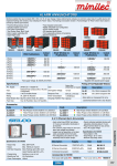
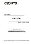
ELECTRONICS, LTD
700 SERIES
SCPC
Satellite Receivers
ZEPHYRUS ELECTRONICS, LTD
168 South 122 East Avenue,
Tulsa, OK 74128-2405 USA
Phone 918-437-3333 Fax 918-438-7322
Web site
http://www.big-z.com
Email
[email protected]
Thank you for using our equipment. We will do our best to
earn your continuing confidence in Zephyrus and our products. Any time you need information or help, give us a
call at 918-437-3333 (US).
It's a good idea to look the equipment over for
any shipping damage as soon as it is received.
If damage is discovered, contact and file a
claim with the freight company. They are
responsible to you.
Our Limited Warranty is as follows:
We will fix or replace any product that is
defective within One year (Australia) after you
receive it. We won't cover damage from
accident or misuse. Warranty is FOB the
factory or our servicing distributor. Our
responsibility is limited to repair or
replacement only and no other expenses or
consequential damages. No other warranties
apply.
We hope it doesn't happen, but if you ever
have a problem that requires you to send
equipment back to us for repair or
replacement, Please pack a note in with the
device. Give us as much information as
possible;-- what the problem is and anything
you can tell us that might help solve it.
Customer feedback is the last line and a very Whether your warranty has expired or not,
customer support and assistance is the
vital part of our overall quality control.
backbone of our business. Our managment
It will also help both of us if you will get an
has a background in broadcasting, so we
RMA number from the service technician you
understand the seriousness of "equipment
are talking with. We will certainly accept
down." We'll do all we can. --Your referral
products for service without a number, but any
to a friend might even be our next sale!
notes that the tech makes in his phone calls
with you might not get tied to your unit when it
gets here.
We make quality affordable
thankyou.sam
OPERATING THE ZEPHYRUS 700 SERIES
SCPC SATELLITE RECEIVER
Table of Contents
SECTION 1
General Information
-An overview and summary description of the system
describing features and design philosophy.
-System specifications and typical operating criteria.
SECTION 2
Front Panel Layout and Operation
-Meter operation and calibration, control information.
-Details of Readout Display and Keypad Data Entry.
SECTION 3
Installation of the 700 Receiver system
-Dish and polarity optimization.
-Notes on signal quality problems.
SECTION 4
SYSTEM OPERATION AND CUSTOMIZATION
-Components to make up a 700 system.
-External connections.
-Locations and use of customer usable jumpers and internal
adjustments.
ZEPHYRUS ELECTRONICS, LTD
168 South 122nd East Avenue
Tulsa, Oklahoma 74128-2405 USA
Pho 918 437-3333 Fax 438-7322
MA700TBL.SAM
Operating the Zephyrus 700 Series
SCPC Satellite Receiver
General information
The 700 receiver system is contained in a 3½" frame
and features microcomputer electronics that control
and monitor operation of either one or two receiver
modules and the LNB. Primary power is normally
117 vac with 240 volt units available. Rack mounting
is optional.
v Input signal to the receiver is L band at
950-1450 MHz and is usually supplied by an
LNB with ±50 kHz stability.
v
v A "relative" RF signal meter monitors amplitude
of the carrier at the demodulator of the first audio
channel. The position of the meter needle may
be changed with the adjustment directly below
the meter. Any variation from this setting will
then be due to a change in the strength of the
received signal. Therefore, it may be used for
peaking the dish and/or day to day monitoring of
system stability, such as dish movement or
cable problems.
v Frequencies of the C or Ku band satellite and
the SCPC frequency are entered through a
keypad. --We use the satellite frequency, rather
than a transponder number, because of the total
lack of any industry standard relating to a
transponder numbering system.
They are
displayed on the top line of the backlit
alphanumeric readout. The bottom line of the
readout gives the results of the fault-monitoring
duties of the processor. The front panel of the
700 frame is sloped to make it easy to read the
LCD display and enter data through the keypad.
v The audio meters are backlit with LED's (low
brightnes level is normal). Light is red if the
channel is in a signal failure (squelch) mode and
is green in normal or squelch defeat operation.
v Squelch of the output audio signal is provided by
circuits that listen for high noise levels. The
squelch may be defeated with front panel
switches located next to the audio meters.
Standard receiver modules are for 15 or 7.5 kHz
audio signals, with others available on special order.
Baby boards on the receiver modules contain audio
process/companding circuits for the particular
system. Deemphasis time is selected with jumpers.
Both balanced and unbalanced output connectors
are provided on the rear panel.
A 70 MHz output is provided for use with external
demodulators. Mode C contacts of a fault-alarm
relay are available at the back panel
General Information MA700OVW.sam
SECTION 11
Zephyrus 700 SCPC Satellite Receiver
Specifications and Typical Operating Criteria
PHYSICAL:
General:
No. of carriers:
Weight:
Size:
Operating range:
Front panel is sloped back for easy viewing and data entry.
Analog meters for signal values. Keypad entry tuning. Illuminated
LCD readout of frequencies and operating status. Audio level
controls on front panel.
One basic with front panel devices included for optional second
channel.
7½ pounds
3½" high, 11½" deep, 16¾" wide (19" with rack ears)
4° - 38° C, non-condensing
ELECTRICAL:
Input Power
Power to LNB
OPERATING:
Satellite Freq.
LNB frequency
Input signal level
SCPC frequencies
RF bandwidth
Audio Bandwidth
Freq. response
Companding
Noise Floor
Distortion
Output
105-125 VAC, 60 Hz, <30 watts (240 VAC 50Hz available)
18 VDC, electronically shut down when shorted
3700-4200 MHz or 11700-12200 (to match tuning logic)
Other frequencies available
950-1450 MHz
-40 dbm max to -85 dbm min typical
50-90 MHz
70 kHz for 7.5 kHz audio, 140 kHz for 15 kHz audio
50 - 15,000 Hz or 50 - 7,500 Hz, per order
within ±1 dB over operating range
2:1 or 3:1, per order
-70 db (2:1), -90db (3:1) typical
<1% @ 1 kHz
+18 dBm max balanced (level meters internally adjustable)
ZEPHYRUS ELECTRONICS, LTD
168 South 122nd East Avenue, Tulsa, Oklahoma 74128-2405 USA
918-437-3333 Fax 918-438-7322
MA700SPC.SAM
SECTION 1, PAGE 2
700 Front Panel Operation
Refer to illustration in Section 1
The 700 is flexible, easy to operate, and provides you with the information needed
to tell what's "going on."
The RELATIVE RF meter actually indicates the amount of limiting taking place in the
CARRIER 1 IF/Demod section. The adjustment, directly beneath it, lets the meter be
set to a convenient operating range for your particular signal. The meter is used for a
peaking indicator while positioning the dish or polarizing the feedhorn. Once the
installation is complete, set the meter to an easy-to-remember number. Any future
deterioration of that setting provides a reason to check for system changes or
problems. NOTE: The meter setting will probably change if a different SCPC carrier
is tuned.
CARRIER 1 & CARRIER 2 meters indicate the audio output levels of each receiver.
CARRIER 1 is always the active channel in single channel (mono) systems. Normal
factory default setting of the meters is Zero dBm into 600 ohms at the balanced output
for a reading of 100 (Zero VU). Output audio level is adjustable with the controls
below each meter. An internal jumper at the very front of the audio demod circuit board
permits an alternate Zero VU setting to indicate +8 dBm out. Custom zero settings
can be set internally also. --See AUDIO OUTPUTS in Section 4, System Operation
and Customization.
Audio squelch is activated by the presence of a high audio noise level. Whenever
squelch occurs, a red LED illuminates the meter face. Audio muting from the squelch
circuitry can be canceled by depressing the tops of the SQUELCH DEFEAT switches.
-Although the squelch defeat disables the red meter lamps, the alarm relay action is
not affected.
The DISPLAY is a backlit two-line LCD readout. The bottom line of text is for fault
messages. The top line shows operating frequencies as follows:
TRANSPONDER: Center frequency of the satellite signal in MHz. C band
transponder frequencies must be entered as a number between 3700 and 4200.
Ku band (for the Americas) must be between 11700 and 12200.
CARRIER 1 & 2: Operating frequency of the individual SCPC carrier as down
converted to the "70 MHz Band." Valid frequencies that may be entered are between
50.00 and 90.00 MHz. Four digits must be entered whether needed or not. -For
example, 81.3 MHz is entered as 8130 and is displayed as 8130.
Front Panel MA700FNT.SAM
SECTION 21
An attempt to enter frequencies outside the permissible range will yield an error
message indicating an INVALID FREQ.
Other FAULT MESSAGES are:
LNBO
Little or no current is flowing to the LNB (LNB Open)
LNBS
Abnormally low resistance on the LNB line (LNB Short)
FAULT-
(followed by any combination of the digits 1,2,3,4,or5)
1,2,3 indicate loss of Tuner, Audio 1, Audio 2 synthesis lock.
4,5 indicate squelch of audio 1 and 2 respectively.
The KEYPAD is used to tune the system. A summary of its use is screened on the back
panel of the receiver. Entry procedure is as follows:
1: The keypad is enabled by punching #Y.
2: Punch 1 to enter transponder frequency or
Punch 2 to enter Audio 1 frequency or
Punch 3 to enter Audio 2 frequency.
3: Enter the appropriate frequency (see DISPLAY, above); four digits for audio or
five digits for a transponder. Ku transponder frequencies are five digits and are
entered directly. C band transponder frequencies are entered as four digits, such
as "3760" followed by a # (3760#).
Caution: If a wrong number is punched in step 2, it can be cancelled by depressing
the Y key. However, once you have started entering any frequency, that
entry must be completed before anything else can be done. Thus, if you have
inadvertently started entering undesired input in the place of previously correct
information, you must complete your entry and then re-enter the original number.
The PANIC BUTTON duplicates the power-on-reset function to the microcomputer. It is
used much the same as a computer reset button. It can not be used to overcome
an incorrect entry as mentioned in the previous paragraph, because the micro writes
frequency entries into non-volatile memory.
Front Panel MA700FNT.SAM
SECTION 22
Installation of the 700 Receiver system
We assume your dish has been mounted and installed
correctly and that you know how to make polarization
and position adjustments.
INPUT SIGNAL to the 700 is via the F connector labeled LNB 950-1450 MHZ. This
signal must be supplied from an LNB or block-converter that is frequency stable to
within ±50 kHz or better.
If you are making a new dish installation, be sure any system gaskets are in place.
Use a connector sealer material, such as "Coax Seal" or a putty type sealer sold by air
conditioner supply stores, around the coax connector. Take care to do a good job as
moisture invading the LNB or cable is one of the most common causes of
system failure.
POINTING AND OPTIMIZING the dish: If you don't have access to equipment other than
your Zephyrus 700 package, take the 700 out to the dish along with a
speaker-amplifier and hook everything up and turn it on. Be sure the signal you are
going to pick up is on the air. Tune the receiver to the correct transponder and SCPC
frequencies with the keypad. Turn on the SQUELCH DEFEAT switch. You will hear
white-noise on the speaker if the system is not aligned.
Use a compass to point the dish to the approximate point in the sky where you expect
to find the satellite. If you don't know where this is, give us a call with the name of the
satellite and your location and we can give you the pointing instructions. -(We have a
short computer satellite locator file called LOOKANGLE that we will be glad to pass on
if you would like).
If you are properly polarized, you will hear the program audio as you zero in on the
satellite. NOTE: If you are having difficulty hearing the audio, it may help to temporarily disable the
Frequency Search feature of the receiver at this time. -See System Operation and Customization.
When you get to this point, use the RELATIVE RF meter to peak your adjustments.
Reset the meter sensitivity pot, if necessary, to keep the meter in an operating range.
Indication of weak signal: Misadjustment of the dish/polarity, LNB trouble, moisture in
the cable connectors, or front end trouble in the satellite receiver can all cause a weak
signal to the demod in the receiver. Any of these can have the effect of causing "pops"
in the program audio as the problem develops. As the problem worsens, the pops get
more frequent, eventually turning to "static" and activating the squelch in the receiver.
The effect is much the same as driving out of range of an FM broadcast station with
your car radio. This type of "front-end" trouble does not affect the tonal quality of the
Installation MA700NST.SAM
SECTION 31
audio. Program audio that has no popping or static noise, but which is distorted (or is
the wrong level) does not come from the above areas. Distortion problems come from
audio processing circuits. This can be in the transmission processing, or the receiver
demod and audio circuits.
BACK INDOORS
When you install your 700 in the rack, the first thing you may notice is that the meter has
a lower reading than it did outdoors. The reason for this is that the metering circuit is
indicating the loss in your cable. Readjust the meter sensitivity to a center value and
make a note of it. If the value drops in the future, look for dish movement, ice or snow in
the dish, water in cables, etc.
Sun fades occur for periods of a few days in the spring and fall and last for a few
minutes. You can verify if this is your signal loss by looking at the sun shadow in the
dish. It will be dead center when this happens.
Notes on Cable: RG-59 cable is usually OK for runs up to 125 to 150 feet. Longer
runs require a heavier cable such as RG-6, or preferably RG-11. The DC resistance of
light duty cables eats up the supply voltage to the LNB on long runs. Any cable you use
must have substantial braid. Foil-only outer conductors are OK to run TV signals
around your house, but not much else. "L" Band line amplifiers can be used for long
runs between the dish and receiver. We have gone as far as 700 feet in special cases.
If you use cables other than RG-59, it is a good idea to use short jumpers of RG-59 on
the ends of the heavy cable. The "F" connectors that go on larger cables often have
such a big center conductor that they can stretch or damage the female connectors on
your LNB or receiver.
In cases of extreme RF fields, you may want to look at triple shield cable such as
Belden 9060. You can probably get some from your nearest Cable TV company if you
don't have a cable dealer nearby.
Installation MA700NST.SAM
SECTION 32
System Operation and Customization
The 700 Series SCPC system can be assembled in a
large variety of configurations to meet specific
requirements.
COMPONENTS to make up a 700 system consist of the following:
1: Basic chassis/case which contains power supply, microcomputer control, and a
complete front panel. See "700 Front Panel Operation" for control and display details.
2: A receiver card (CARRIER 1) for the #1 SCPC carrier, which also contains the L band
transponder tuner. Optionally, the CARRIER 1 card can be supplied without L band
reception. In this configuration, the system functions as a 70 MHz receiver
3: An optional receiver card (CARRIER 2) for the #2 SCPC carrier. This card receives a
70MHz IF signal from the Carrier 1 card. -The Carrier 2 card has an IF buffer so that
the 70 MHZ IF is available to loop to other demodulators, if needed.
4: Audio processor "baby boards" for the receiver cards. These contain companding
circuits (3:1 or 2:1 typical) and deemphasis, if used.
COAX CONNECTIONS and their functions -back panel (see Fig.2) :
J10 is the LNB (or block converter) connector. Besides providing the input signal to
the 700, it provides 18 volt DC power to the LNB. This power output is protected
against short circuit with a "crowbar" circuit that shuts down power in the event of a
momentary flow of excess current. Once a short has occurred, it may be necessary to
completely open the LNB cable feed, or momentarily disconnect primary power before the
crowbar circuit will permit resumption of DC.
The 18 VDC output for the LNB is diode protected, so multiple 700 receivers can be
connected to a common LNB via L band splitters without concern. If it becomes
necessary to remove the DC voltage from the coax, the jumper wire closest to the back
of the tuner, looping down to the circuit board can be clipped. (see Fig. 1)
If multiple receivers are connected to an LNB, the display can indicate LNB Open on any
receiver that is not furnishing enough current to extinguish the LNBO warning. -This condition
will NOT activate the alarm relay.
70 MHz IF loops are made with RG59 "F" jumpers. A two channel receiver requires a
jumper from J9-IF OUT to J4-IF IN. J5-IF OUT is the 70 meg source for external
devices. NOTE: As the squelch system runs on noise, the squelch will not operate if the 70
System Operation MA700SYS.SAM
SECTION 41
MHz feed is removed from an operating demod causing AFC to lock out of range. It may
require up to a minute for lockup when the 70 MHz baseband feed is restored.
ALARM RELAY (J-1) NO and NC contacts are available to drive external customer
equipment. The alarm relay is a miniature type (rated at 1 amp AC max) and is
intended to drive control type circuits only.
AUDIO OUTPUTS: Both balanced and unbalanced outputs are provided. Balanced
outputs are 600 ohms with a 300 ohm source termination in each leg. The unbalanced
output is tapped off of one of the "hot" balanced terminals with an additional 300 ohms
in series to the output phono jack.
The factory meter calibration is made to the balanced output with a 600 ohm load. If
only the unbalanced output is used into 600 ohms, the signal will be 6 dB down. If the
600 ohm balanced output is used for program purposes and the unbalanced output is
used for monitoring, the unbalanced load should be Hi-Z to preclude unbalancing the
program output.
METER CALIBRATION: (see Fig. 1) Two factory calibrations are provided for audio
output; 0 dBm and +8. The 700 is shipped in the zero mode. To change to the +8
mode, remove the top cover of the receiver and locate the 3-pin header J 10. Move
the shorting plug from pins 2 and 3 over to pins 1 and 2.
If a level other than +8 or 0 is desired, change the output level of the receiver to the
level desired, using the front panel level adjustment. Note meter calibration pots VR5
and VR6 at each end of the header. Each pot sets the calibration of the respective
end of the header pins. These pots can be adjusted to calibrate the meter to a
customer defined value in either or both positions.
FREQUENCY SEARCH (and disable of same): Whenever the audio noise level
becomes high, a noise-sensing squelch circuit is activated. In addition to muting the
audio and causing the alarm relay to close, the receiver AFC is disabled and replaced
by a variable tuning voltage. This voltage scans frequencies to 50 kHz below and
above the specified SCPC carrier frequency, thus compensating for LNB
downconverters which might be off frequency.
This feature can be disabled by removing the jumper on header J2 on the receiver
board (see Fig.1).
AUDIO PROCESSOR BOARDS are the baby boards mounted in a vertical direction on
the edge of the receiver cards. Companding schemes and adjustments are to the
customer's specification and are not field adjustable.
Deemphasis time is alterable with jumper placement. Instructions for settings from 0
to 100 microsecond time are etched on the top of the boards.
System Operation MA700SYS.SAM
SECTION 42
Figure 1
Channel 1 Receiver Board
(Channel 2 is similar but less tuner)
System Operation MA700SYS.SAM
SECTION 43
SECTION 4, PAGE 4
Figure 2
700 Receiver Back Panel
MA700SYX.SAM