1
98
Remote Control
Machine Control Function
The 01V96i can control the transport functions and select
tracks on external recording machines that support MMC by
transmitting commands via the MIDI OUT port or USB port.
Note: Controllable parameters vary depending on the connected
devices. Refer to the User’s Manual for the external device for
more information on controllable parameters.
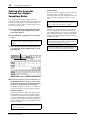
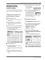
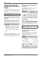
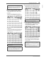
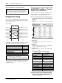
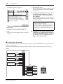
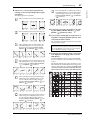
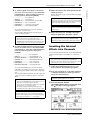
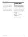
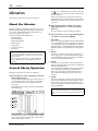
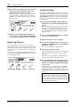
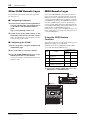
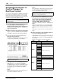
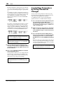
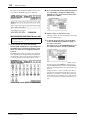
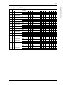
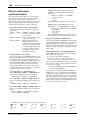
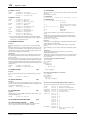
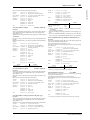
1. Refer to the diagram below for information
on connecting the 01V96i to an external
device.
• MIDI .................MIDI port
• USB....................USB port
• SLOT .................Slot with an MY16-mLAN (mLAN card)
installed
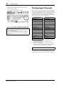
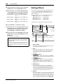
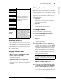
If USB is selected, move the cursor to the adjacent parameter box (on the right), and select one of eight ports.
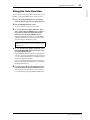
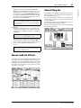
4. Move the cursor to the DEVICE ID parameter
box, then rotate the Parameter wheel to set
the 01V96i MMC Device ID to the same ID
number as the external device.
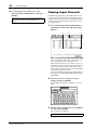
MMC commands are effective on devices that use the
same Device ID. Therefore, the MMC Device ID needs to
match the ID of the devices you wish to control.
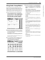
5. Press the DISPLAY ACCESS [DIO/SETUP] butMIDI OUT
MIDI IN
CH1-4
1
2
3
4
5
6
7
8
9
10
11
MIDI OUT
CH5-8
12
13
15
MIDI IN
CH9-12
PHANTOM +48V
L
A
A
A
A
A
A
A
A
A
A
A
A
B
B
B
B
B
B
B
B
B
B
B
B
14
16
R
IN
INPUT
ton repeatedly until the DIO/Setup | Machine
page appears.
OUT
2TR
(BAL)
-10dBV (UNBAL)
PHONES
INSERT
OUT IN
(UNBAL)
INSERT I/O
INSERT I/O
INSERT I/O
INSERT I/O
INSERT I/O
INSERT I/O
INSERT I/O
INSERT I/O
INSERT I/O
INSERT I/O
INSERT I/O
INSERT I/O
20dB
20dB
20dB
20dB
20dB
20dB
20dB
20dB
20dB
20dB
20dB
20dB
CH15/16
2TR IN
MONITOR
2TR IN
PAD
+4 GAIN -26
+4 GAIN -26
0
LEVEL
10
MONITOR
OUT
-16
-60
-16
-60
-16
-60
-16
-60
-16
-60
-16
-60
-16
-60
-16
-60
-16
-60
-16
-60
-16
-60
GAIN
GAIN
GAIN
GAIN
GAIN
GAIN
GAIN
GAIN
GAIN
GAIN
PEAK
SIGNAL
PEAK
SIGNAL
PEAK
SIGNAL
PEAK
SIGNAL
PEAK
SIGNAL
PEAK
SIGNAL
PEAK
SIGNAL
PEAK
SIGNAL
PEAK
SIGNAL
PEAK
SIGNAL
PEAK
SIGNAL
DISPLAY ACCESS
DIO/SETUP
SCENE
-16
+4 GAIN -26
-60
GAIN
GAIN
PEAK
SIGNAL
13
0
LEVEL
+4 GAIN -26
PEAK
14 15
SIGNAL
PEAK
16
SIGNAL
SCENE MEMORY
MIDI
UTILITY
PAIR/
GROUP
PATCH
STORE
RECALL
SOLO
10
PHONES
MMC-supported
machine
2
1
CLEAR
OVER
PAN/
/ INSERT/
ROUTING
DELAY
0
-3
-6
EQ
DYNAMICS
EFFECT
DEC
INC
-9
VIEW
-12
FADER MODE
-15
-18
-24
-30
AUX 1
AUX 2
AUX 3
AUX 4
-36
HIGH
Q
-48
STEREO
AUX 5
AUX 6
AUX 7
AUX 8
HIGH-MID
FREQUENCY
HOME (METER)
LOW-MID
LAYER
ENTER
1-16
17-32
LOW
GAIN
MASTER REMOTE
ST IN
SEL
SEL
SEL
SEL
SEL
SEL
SEL
SEL
SEL
SEL
SEL
SEL
SEL
SEL
SEL
SEL
SOLO
SOLO
SOLO
SOLO
SOLO
SOLO
SOLO
SOLO
SOLO
SOLO
SOLO
SOLO
SOLO
SOLO
SOLO
SOLO
ON
ON
ON
ON
ON
ON
ON
ON
ON
ON
ON
ON
ON
ON
ON
ON
1
2
3
4
5
6
7
8
9
10
11
12
13
14
15
16
+10
0 +10
5
0 +10
5
0
0
5
0
5
0
10
0
10
0 +10
5
0
0 +10
5
5
5
0
10
0
0
5
5
0
10
10
10
10
15
15
20 10
20 10
20 10
20 10
20 10
20 10
20 10
20 10
20
20
30 15
30 15
30 15
30 15
30 15
30 15
30 15
30 15
30 15
30 15
30 15
30 15
30 15
30 15
30 15
30
30
20
40 20
40 20
40 20
40 20
40 20
40 20
40 20
40 20
40 20
40 20
40 20
40 20
40 20
40 20
40 20
40
40
30
50 30
60 40
70
50
50 30
60 40
70
50
50 30
60 40
70
50
50 30
60 40
70
50
50 30
60 40
70
50
50 30
60 40
70
50
50 30
60 40
70
50
50 30
60 40
70
50
50 30
60 40
70
50
50 30
60 40
70
50
50 30
60 40
70
50
50 30
60 40
70
50
50 30
60 40
70
50
50 30
60 40
70
50
50 30
60 40
70
50
50
50
60
70
60
70
5
15
5
15
20 10
40
50
1
5
15
20 10
2
5
15
20 10
3
4
5
15
5
5
15
6
5
15
7
5
15
5
15
20 10
8
5
15
20 10
9
5
15
10
5
15
20 10
20 10
11
12
5
15
13
5
15
14
SEL
SOLO
ON
ON
ST IN 1
15
10
SEL
SOLO
ON
ST IN 2
5
5
0
10
0 +10
5
5
0
10
10
0 +10
5
5
5
0
10
0 +10
5
5
5
0
10
0 +10
0 +10
5
5
0
10
0 +10
5
5
0
10
0 +10
5
5
0
10
0 +10
5
5
0
10
0 +10
5
5
5
10
0 +10
0 +10
5
5
SEL
5
15
15
5
USER DEFINED
KEYS
1
2
3
4
5
6
7
8
16
17
18
19
20
21
22
23
24
25
26
27
28
29
30
31
32
AUX 1
AUX 2
AUX 3
AUX 4
AUX 5
AUX 6
AUX 7
AUX 8
BUS 1
BUS 2
BUS 3
BUS 4
BUS 5
BUS 6
BUS 7
BUS 8
STEREO
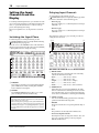
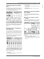
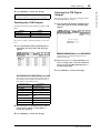
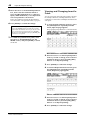
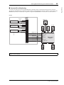
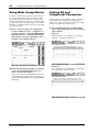
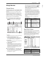
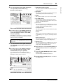
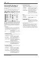
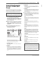
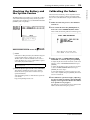
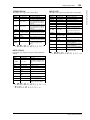
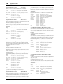
2. Press the DISPLAY ACCESS [DIO/SETUP] button repeatedly until the DIO/Setup |
MIDI/Host page appears.
4
3
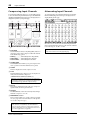
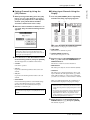
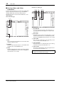
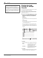
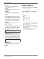
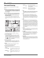
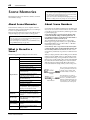
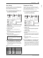
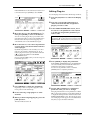
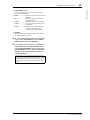
This page contains the following parameters:
1 LOCATE/TIME section
1
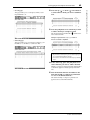
3. Move the cursor to the PORT parameter box
in the MACHINE CONTROL section (1), then
rotate the Parameter wheel to select the
MMC destination.
The following ports and slot are available as the MMC
destination.
01V96i—Reference Manual
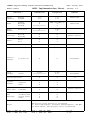
This section enables you to set the locate points.
• LOCATE 1–8..........These buttons locate the positions
(specified by the TIME values) on
external machines.
• RTZ...........................This Return To Zero button locates
the zero timecode position on external machines.
• TIME........................Locate points are specified in
hour/minute/second/frame format.
• CAPTURE ..............These buttons capture the current
position on external machines and
import the information into the
TIME column.
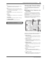
2 TRACK ARMING section
This section controls the tracks on external machines.
• 1–24 buttons...........These buttons turn external tracks
1–24 on or off, and set or cancel their
Record Ready mode.
• ALL CLEAR............Turning on this button switches all
buttons (1–24) simultaneously.