1
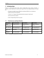
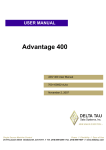
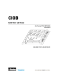
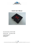
Prostar User’s Manual
Document Number : MN-RPS 0301
Revision Date:
28 October, 2008
© VisionXtreme Pte Ltd
Singapore 339416
www.vxgp.com
Blk 25 Kallang Ave #06-04 Kallang Basin Industrial Estate Singapore 339416 Tel: (65) 6392 0900 Fax: (65) 6392 2103 Company Registration No.:
200104387H
Table of Contents
Table of Contents
1 Introduction ...........................................................................................................4
1.1
Performance and Specification.................................................................................4
1.2
Mechanical Specifications.........................................................................................5
1.3
Environmental Requirements....................................................................................6
1.3.1
Temperature and Humidity...................................................................................6
1.3.2
Ventilation ............................................................................................................6
1.4
Precautions.................................................................................................................6
1.4.1
Input Power..........................................................................................................6
1.4.2
Transportation......................................................................................................6
1.4.3
Warranty precautions...........................................................................................6
2 Prostar Interface ................................................................................................7
2.1
General Description ...................................................................................................7
2.1.1
2.2
Connector Details ................................................................................................7
Pin Assignments ........................................................................................................8
2.2.1
15-pin D-sub connector interface of Prostar ........................................................8
2.2.2
3-pin male connector of Prostar...........................................................................8
2.2.3
DC Power socket for power supply......................................................................8
2.2.4
37-pin D-Sub Connector for Light Head Connection............................................8
2.3
Physical Interface.....................................................................................................10
2.3.1
Camera Interface to Prostar...............................................................................10
2.3.2
I/O card or Parallel Port Interface to Prostar ......................................................10
2.3.3
Light head Interface to Prostar...........................................................................10
3 Hardware and Software Installation................................................12
3.1
Requirements ...........................................................................................................12
3.2
Software Installation ................................................................................................12
3.2.1
Installation Procedures ......................................................................................12
3.2.2
Custom design Application.................................................................................15
3.2.3
Light controlling libraries ....................................................................................15
3.3
Hardware Installation ...............................................................................................16
Prostar User’s Manual
2
Table of Contents
4 Operations and Features .........................................................................18
4.1
Hardware Configuration ..........................................................................................18
4.1.1
16/32 Segment Selection for one channel .........................................................18
4.1.2
Positive / Negative Trigger (strobe) from Camera..............................................18
4.2
Software Configuration............................................................................................18
4.2.1
Controllers For 16 Segment Light Head ............................................................20
4.2.2
Controllers For 32 Segment Light Head: ...........................................................21
4.2.3
Channels ...........................................................................................................23
4.2.4
External Strobe Mode ........................................................................................24
4.2.5
Bank Switching ..................................................................................................25
4.2.6
All Lights ............................................................................................................25
4.2.7
Saving/Loading multiple configurations .............................................................25
4.3
Steps to be followed for configuring the Prostar ..................................................26
Prostar User’s Manual
3
1Introduction
1 Introduction
Prostar is a Dual Board High Power Strobe Programmable Light Intensity Controller. It
operates in Strobe Mode with an external strobe signal. Some of the important features of Prostar
are
• Provides a Very High Current of 220mA for strobed and 50mA for non-strobed per
segment channel of the Light Head
• Control 16 or 32 segment Light Head selection by jumper for each board
• External Strobe Mode (Default)
• Positive / Negative Edge selection by jumper
1.1
Performance and Specification
Specification
32CH non-strobed
32CH strobed
64CH strobed
Power
Requirements
+24VDC, 2.1A max
+24VDC, 8.0A max
(Pulsed)
+24VDC, 15.0A max
(Pulsed)
Bank Switching
High speed Bank Switching
for 16 segment Light
High speed Bank Switching
for 16 segment Light
High speed Bank Switching
for 16 segment Light
Strobe Pulse
Time
Non-strobed
8 milliseconds (max)
8 milliseconds (max)
Dimension
257 X 190 X 82 MM
257 X 190 X 82 MM
257 X 190 X 82 MM
Table 1.1: Performance Specifications of Prostar
Prostar User’s Manual
4
1Introduction
1.2
Mechanical Specifications
Figure 1.1: Prostar(64 channel strobed) Mechanical Dimension
Prostar User’s Manual
5
1Introduction
1.3
Environmental Requirements
1.3.1 Temperature and Humidity
Housing temperature during operation:
0° C … + 50° C (+ 32° F … +122° F)
Storage temperature:
- 20° C … + 80° C (-4° F … +176° F)
Humidity during operation:
20% … 80% relative, without condensation
Storage humidity:
20% … 80% relative, without condensation
1.3.2 Ventilation
The Prostar housing is provided with ventilation fan so as to maintain the temperature below 40ºC
during operation.
1.4
Precautions
Read the Prostar user’s manual carefully before using the product
1.4.1 Input Power
Reversing of the polarity of the input power to the Prostar connector will damage it.
1.4.2 Transportation
Transportation of the product should be done in the same packaging.
1.4.3 Warranty precautions
•
Opening the casing
Do not open the casing. If the product is disassembled, reworked or repaired by other than
recommended service person, we will not take the responsibility of any subsequent
malfunctioning of the product.
•
Keep out of foreign matters
Be careful not to allow liquid, flammable, or metallic material inside the housing. If operated
with any foreign matter inside, the Prostar may fail or malfunction
Prostar User’s Manual
6
2 Prostar Interface
2 Prostar Interface
This section provides the detailed information on connector pin-out, physical interface and voltage
requirements for the Prostar.
2.1
General Description
The Prostar is interfaced with either I/O card installed in PC or printer port.
2.1.1 Connector Details
There are five types of connectors in Prostar.
•
15-pin D-Sub Connector for interface with I/O or parallel port
•
3-pin male Connector for strobe from camera
•
DC Power socket for power supply
•
37-pin D-Sub Connector for Light Head Connection
The different connector views are shown in the below figures
Prostar User’s Manual
7
2 Prostar Interface
2.2
Pin Assignments
2.2.1 15-pin D-sub connector interface of Prostar
The 15-Pin D-sub connector is used to provide control signals and data to the Prostar. The pin
assignment of 15-pin D-sub connector is shown below
15-pin Connector (Master)
Signal Description
1
SELECT1 BIT0
2
SELECT1 BIT1
3
SDA1/ SCL1
4
SDA2/ SCL2
7
LEDSTR
8
BANK SW
10
GND
Table 2.1: Pin out of 15-Pin D-sub connector to control Prostar
2.2.2 3-pin male connector of Prostar
The pin assignment of the male connector of Prostar with respect to the signals from camera is
shown in Table 2.2.
Signals from camera
Strobe
GND
NA
3-pin male connector
1
2
3
Table 2.2: Pin out of 3-Pin male connector
2.2.3 DC Power socket for power supply
The power requirement of Prostar is +24V, 14.1A(current depends on light head). Table 2.3 shows
the pin assignments between the power supply and the Prostar
Signals from Power
supply
+12V
GND
DC Power socket
1
2
Table 2.3: Power supply interface with Prostar.
2.2.4 37-pin D-Sub Connector for Light Head Connection
The 37-Pin connector of Prostar is used to provide the light intensity output from Prostar to the
16/32 segment Light Head.
Prostar User’s Manual
8
2 Prostar Interface
26-pin Connector
Pin
1
Signal
+24V
2
Input1
3
Input2
4
Input3
5
Input4
6
Input5
7
Input6
8
Input7
9
Input8
10
+24V
11
Input9
12
Input10
13
Input11
14
Input12
15
Input13
16
Input14
17
Input15
18
Input16
19
Input17
20
Input18
21
Input19
22
Input20
23
Input21
24
Input22
25
Input23
26
Input24
27
Input25
28
Input26
29
Input27
30
Input28
31
Input29
32
Input30
33
Input31
34
Input32
35
NC
36
NC
37
NC
Table 2.1: Pin out of 37-Pin D-sub connector to control Lighthead
Prostar User’s Manual
9
2 Prostar Interface
2.3
Physical Interface
2.3.1 Camera Interface to Prostar
The Prostar is set to External Strobe Mode by default. The camera interface provides a control
signal called “Strobe” from Camera to the Prostar.
Signals from camera
STROBE
GND
3-pin male Connector
1
2
Table 2.4: Camera Interface with Prostar
2.3.2 I/O card or Parallel Port Interface to Prostar
The parallel port interface to the Prostar provides the data and control signals from PC to the
Prostar. The pin assignments between the Parallel port, I/O port and the 15-pin D-Sub connector
are shown in Table 2.5.
25-pin connector
(Parallel)
2
25-pin connector
(I/O)
2
3
4
15-pin Connector
Signal Description
1
SELECT1 BIT0
3
2
SELECT1 BIT1
4
3
SDA1/ SCL1
5
5
4
SDA2/ SCL2
6
6
7
LEDSTR
7
7
8
BANK SW
18
18
10
GND
Table 2.5: Parallel port or I/O interface to Prostar
2.3.3 Light head Interface to Prostar
To 37-pin Lighthead Connector
32 segment Light
+ 24VDC
1, 10
2 to 9
11 to 26
Prostar User’s Manual
1,10
OUTPUT
OUTPUT
2 to 9
11 to 26
10
2 Prostar Interface
32 segment Light
37-Pin Male
(To 37-pin Lighthead
Connector)
Fig 2.5: Lighthead Cable
LED Electrical Circuitry
The lighthead can be designed according to any of the following LED connectivity options. Few
sample circuits are shown below
+ 24VDC
+ 24VDC
OR
OUTPUT
Prostar User’s Manual
OUTPUT
+ 24VDC
OR
OUTPUT
11
3 Hardware and Software Installation
3 Hardware and Software Installation
This section provides the initial hardware and software installation procedures to work with Prostar
3.1
Requirements
Following are the required hardware and software components to start the installation
1. Prostar
2. Power Supply
A power supply of +24VDC is required for powering the Prostar
3. Interfacing cables
Prostar requires 3 types of cables (Power Supply Cable, Control Cable and Strobe Cable) that
come with package. For 32CH non-strobed, strobe cable is not needed.
4. Software package
The Software package includes necessary files to install the API and driver. The application can
run in Windows 2000 or Windows XP platforms
3.2
Software Installation
This section explains in detail about the software installation of lighting controller using the setup
file provided with the installation disk.
3.2.1 Installation Procedures
Follow the steps below to install the API.
1. Double click the setup file and run
Prostar User’s Manual
12
3 Hardware and Software Installation
2. The following LightController setup wizard opens. Click Next button to continue the setup
3. Choose the folder you want to install.
Prostar User’s Manual
13
3 Hardware and Software Installation
4. Click Next to start installation.
5. Click Close the complete the installation
Prostar User’s Manual
14
3 Hardware and Software Installation
6. You can see the LightController shortcut icon automatically created in the desktop
To start working with LightController, double click on the icon.
3.2.2 Custom design Application
The Installation setup contains following items
1) Exe for LightControl Application.
2) 4 DLLS - VX_MicroProstar.dll, VX_RegularProstar.dll, VX_IcubeC.dll, VX_ParallelPort.dll
3) 3 LIB Files - VX_MicroProstar.Lib, VX_RegularProstar.Lib, VX_IcubeC.Lib
4) 3 include Files - nProstar.h, uProstar.h, IcubeCControl.h
All the above files will be located in the installation folder after installation ( Default installation
location is" ProgramFiles\VisionXterme\LightController"). The user can design their own application
using the library and dlls provided as below
•
•
•
The library file VX_RegularProstar.lib has to be referenced in the project.
The DLL file VX_RegularProstar.dll and VX_ParallelPort.dll are used for light control and
parallel port communication respectively.
The header file RegularProstar.h with the function declarations, to be included in a project.
All function calls are explained in the next section 3.2.3
End users also have option to develop their own communication library instead of parallel port
(VX_ParallelPort.dll) and link dynamically.
3.2.3 Light controlling libraries
1) int Initialize (int cardNo, int portID, char* commLibrary): Loads and registers the required
communication library
cardNo: Index of Communication card being used. For Parallel port, cardNo is the
parallel port’s base address… usually 888
• portID: Port Id of the communication card. Unused for Parallel Port
• commLibrary: Name of the communication library (e.g., “Vx_ParallelPort”)
Returns 0 for success and -1 for failure.
•
2) int SetLight (int controller, int channel, int level): Sets light intensity for a particular
segment.
• controller: Prostar controller number of the segment to be controlled (0 to 7)
• channel: Prostar channel number of the segment to be controlled (0 to 3)
• level: Intensity level to be set (0 to 63)
Returns 0 for success and -1 for failure.
Prostar User’s Manual
15
3 Hardware and Software Installation
3) int SetBank (byte bank): Sets either bank0 or bank1 to be used.
• bank: Bank index to be set (0 or 1).
Returns 0 for success and -1 for failure.
4) void SetPinMap(byte* pinMap): Makes user defined pin assignments for communication
interface.
•
pinMap: A byte array of 4 elements (clock, data, bank1, address), containing pin
assignment.
5) int Free(): Releases the interface card. To be called while exiting user application.
Returns 0 for success and -1 for failure.
3.3
Hardware Installation
•
Plug in power cable into the DC Power connector of Prostar
•
Connect the Master cable from Printer port or I/O card port control connector of Prostar
•
Connect the strobe cable connector to the I/O cable connector of camera (for strobed)
•
Connect the lighthead to the other end of the Prostar
Please see picture below for connecting up the Prostar for I/O card interface
Fig 3.1: I/O card interface of Prostar
Prostar User’s Manual
16
3 Hardware and Software Installation
The Prostar can also be interfaced with PC printer port and necessary cables. Please see picture
below for connecting up the Prostar.
Fig 3.2: printer port Interface of Prostar
Prostar User’s Manual
17
4 Operations and Features
This chapter explains the basic operations and features of Prostar. Prior to the operation of Prostar,
hardware and software configurations have to be done. This section also explains the configuration
in detail.
4.1
Hardware Configuration
This section explains various hardware configurations in detail.
4.1.1 16/32 Segment Selection for one channel
Prostar can control either 16 segment Light Head in Bank Switching mode (jumper E4 at Dual
Switch) or 32 segment Light Head with Bank0 and Bank 1 configuration (jumper E4 at No Switch).
Note that this setting has to be done by authorized Customer Service Engineer by opening up the
casing.
4.1.2 Positive / Negative Trigger (strobe) from Camera
Prostar is designed to work with either Positive trigger or Negative trigger from
camera. This
can be achieved by setting the jumper E1 (Positive) or E2 (Negative) on board. Please note that
E1 and E2 should not be ON together at any one time.
4.2
Software Configuration
The application for Prostar runs either in Windows 2000 and Windows XP platforms. This section
explains the configuration of various light patterns intensity levels using the API provided. Figure
4.1 shows the appearance of Prostar application.
Prostar User’s Manual
18
Fig 4.1: Prostar Light Controller
Once the application is opened, ensure “Regular Prostar” is selected under device. If not click on
the box as shown in Fig.4.2
Prostar User’s Manual
19
Fig. 4.2: Prostar Device Selection
4.2.1 Controllers For 16 Segment Light Head
There are 4 Controllers namely Controller 1, Controller 2, Controller 3 & Controller 4, as shown in
Figure 4.3. For example the channels for Controller 2 are shown in Figure 4.3. The “Select All”
button is provided to select all the controllers and channels.
Prostar User’s Manual
20
Fig 4.3: Channels of Controller 2
4.2.2 Controllers For 32 Segment Light Head:
There are 4 Controllers namely Controller 1, Controller 2, Controller 3 & Controller 4 for Bank 0 as
shown in Figure 4.4. There are another 4 Controllers namely Controller 1, Controller 2, Controller 3
& Controller 4 for Bank 1 as shown in Figure 4.5.
Prostar User’s Manual
21
Fig 4.4: Controllers of Bank0
Prostar User’s Manual
22
Fig 4.5: Controllers of Bank1
4.2.3 Channels
There are 4 Channels namely Channel 1, Channel 2, Channel 3 and Channel 4, per Controller. For
example the Controllers for Channel 3 are shown in Figure 4.6
Prostar User’s Manual
23
Fig 4.6: Controllers of Channel 3
4.2.4 External Strobe Mode
This feature is provided to operate Prostar with only External Strobe signal. The light head strobes
in sync with the external strobe signal connected to the board.
Strobe Pulse width variations
• This feature is provided to vary the pulse width of the strobe output from Prostar with
respect to the Trigger from camera.
• The strobe output of Prostar decides the Turn on time of the light head.
• The pulse width of the strobe output from Prostar is default at 8 milliseconds (max).
Prostar User’s Manual
24
4.2.5 Bank Switching
Bank switching feature is provided for storing two different sets of light configurations. “Bank 0” and
“Bank 1 “ are the two banks provided in the “Prostar Light Controller” application software, between
which the switching can be performed. “Bank 0” can store one set of light configuration and “Bank
1” can store another set of light configuration.
4.2.6 All Lights
The value for maximum intensity is 63 and 0 for minimum intensity. The “Switch On” and the
“Switch Off” buttons under “All Lights” option is provided to switch on all lights (all controllers and
channels) to the maximum Intensity or turned off respectively.
4.2.7 Saving/Loading multiple configurations
Save and Load Configuration features are includes in the API for strong multiple configurations and
loading the configuration on to the Prostar for quick setup.
Save Configuration:
This option is provided to save the light configuration settings. Number of configuration files saved
depends on the hard disk capacity.
Load Configuration:
This option is provided to load the saved configuration settings on to the Prostar. Pre-stored files
can be reloaded for quick setup.
Exit:
This option is provided to close the Prostar application.
Prostar User’s Manual
25
4.3
Steps to be followed for configuring the Prostar
Step 1: Bank Selection
Select the required Bank, either Bank 0 or Bank 1. (Refer note). For example, Bank 0 and Bank 1
selection is shown in figure 4.7 and 4.8.
Note: The default selection is Bank 0.
Fig 4.7: Bank 0 selection
Prostar User’s Manual
26
Fig 4.8: Bank 1 selection
Prostar User’s Manual
27
Step 2: Selection of Light segments
Choose the configuration style from below, and then follow the steps given with respect to the
required configuration style.
(a) Configuration Styles:
• Selection of all lights.
• Selection of individual light or group of lights.
(b) Selection of all lights:
• All lights (i.e. all controllers and channels) are selected by simply clicking the box as
shown in figure 4.9.
• The intensity value at selection is zero.
Fig 4.9: Selection of all lights
Prostar User’s Manual
28
(c) Selection of individual light segment:
Select the light segment required to be configured as shown in figure 4.10. For example Controller
3,Channel 1 is selected in figure 4.10.
Fig 4.10: Selection of Individual light segment (Controller 2,Channel 0)
(d) Selection of Group of Lights:
•
•
If the requirement is that all the controllers are to be selected for a particular Channel, then
click the corresponding button number of controller for that channel. Refer Fig.4.11.
If the requirement is that all the channels are to be selected for a particular Controller, then
click the corresponding button number of channel for that controller. Refer Fig.4.12
Prostar User’s Manual
29
Fig 4.11: Selecting all controllers of channel 2
Fig 4.12: Selecting all channels of Controller 3
Prostar User’s Manual
30
Step 3: Selection of Light Intensity:
• Light Intensity value can be varied from 0 to 63.The value 0 represents the minimum intensity
and the value 63 represents the maximum intensity.
• The light intensity required to be set could be obtained by moving the cursor between minimum
and maximum value as shown in figure 4.13.
Fig 4.13: Light Intensity value set to 30 for all channels of controller 4
Example: To set maximum intensity value for all light segments, first select all light segments
then move the cursor to intensity value 63. Please refer to figure 4.14 and figure 4.15.
Prostar User’s Manual
31
Fig 4.14: All light segments are selected.
Fig 4.15: Intensity value is set to 63
Prostar User’s Manual
32
Other method to Switch on all light segments with maximum intensity:
All Light segments can be switched on at one time to a maximum intensity by clicking the “Switch
On” button without selection of any controller and channel as shown in figure 4.16.
It can be switched off by clicking the “Switch Off” button.
Fig 4.16: All light segments switched on to maximum intensity
If different Light intensity values are set for different controllers and channels and if the requirement
is such that all the intensity values of the controllers and channels needs to be increased uniformly
in steps of one, then it could be implemented using the Up and Down arrow buttons in keyboard.
Example: Consider controller 1 is set to intensity value 10, controller 2 is set to 20, controller 3 is
set to 30 and controller 4 is set to 40, then by clicking the Up arrow once, the intensity value of the
controllers will get increased uniformly by one i.e., intensity value of controller 0 is set to 11,
controller 1 to 21,controller 2 to 31,controller 3 to 41.To decrease the intensity by one step, use the
Down arrow button.
Prostar User’s Manual
33
Step 4: Saving the configuration
The entire configuration set can be saved for future usage. The Configuration data can be saved in the
location/ folder, where the Prostar application is placed or in any other preferred directory. The
configuration data is saved with .pro extension. Figures 4.17 and 4.18 illustrate how to save
configuration.
Fig 4.17: Click the “Save Configuration” Button.
Prostar User’s Manual
34
Fig 4.18: Select the location where the configuration data is required to be saved.
Note: After setting the light pattern for Bank 0, light pattern for Bank 1 can also be set by
following the steps 1 to 4.
Step 5: Loading the Saved Configuration
The stored configuration can be loaded on to the Prostar by clicking the “Load Configuration”
button. Figures 4.19 and 4.20 illustrate the loading of the stored configuration on to the Prostar
Prostar User’s Manual
35
Fig 4.19: Click the “Load Configuration” button.
Prostar User’s Manual
36
Fig 4.20: Select the location, which contains the saved configuration.
Then click the “Open” Button, to load the configuration on to the Prostar.
Note: The above-mentioned steps should be followed for different light configurations as per the
user requirement.
Prostar User’s Manual
37