1
DRS Digital Recording Solution Series
Installation and Maintenance Guide
v 1.1
DRS5116
Important Notices
FCC Compliance Statement
Caution: Any changes or modifications in construction of this device which are not approved, the
party responsible for compliance could void the user's authority to operate the equipment.
NOTE: This equipment has been tested and found to comply with the limits for a Class A digital
device, pursuant to part 15 of the FCC rules.
These limits are designed to provide reasonable
protection against harmful interference when the equipment is operated in a commercial environment.
This equipment generates, uses, and can radiate radio frequency energy and, if not installed and used in
accordance with the instruction manual, may cause harmful interference to radio communications.
Operation of this equipment in a residential area is likely to cause harmful interference, in which case
the user will be required to correct the interference at his own expense.
Warning
This is a class A product.
In a domestic environment this product may cause radio interference, in which
case the user may be required to take adequate measures.
CAUTION
1.
If the battery is replaced incorrectly, an explosion is plausible. . Replace the battery with only the
same or equivalent type.
2.
Do not improperly dispose of used batteries against the government’s environmental pollution
general recommendations.
3. Do not throw the batteries into a fire, and do not heat, short-circuit or attempt to disassemble the
batteries.
4.
Do not attempt to recharge the batteries.
DRS5116
Important Notices
Important Notice
1. Do not place heavy objects on top of the DRS unit.
2. DRS units are for indoor use only.
They are not weatherproof.
environmental specifications (Temperature & Humidity).
Always referr to DRS’s
To clean the DRS, gently wipe the outside
with a clean dry cloth.
3. Be careful not to drop the DRS.
Physical shocks may harm the product.
In addition, be sure the
DRS is secured after installation.
4. If DRS does not operate properly, please contact your Wren reseller for after-sales service.
Tampering
or disassembling the product will void the warranty.
5. Security surveillance laws may differ for each location.
Therefore, please check with the local
ordinances to avoid any surveillance law violations.
DRS Power Requirements
* Be cautious not to cause electrical damage to the unit by applying
other voltages.
DRS5004
DRS5008
DRS5016
DRS5116
* 12VDC
* 12VDC
110V ~ 220VAC
110V ~ 220VAC
* Be sure to use
the DC Adaptor
provided by Wren.
directly to an AC current will damage the DRS unit.
Connecting
Table of Contents
DRS5116
Table of Contents
Overview ......................................................................................................... 10
1.
What is DRS Digital Recording Solution? .................................................................10
2.
Component List .......................................................................................................... 11
3.
Description & Function ..............................................................................................12
Installation and Connection........................................................................... 18
4.
Connecting & Running ...............................................................................................18
4.1.
Connecting Camera ..................................................................................................18
4.2.
Connecting Monitor ...................................................................................................19
4.3.
Connecting Audio......................................................................................................19
4.4.
Supplying Power .......................................................................................................20
5.
Running OSD Menu ....................................................................................................22
5.1.
Using Menu...............................................................................................................22
5.2.
Dialogue Box to Edit a Word......................................................................................23
6.
Setting Remote Controller..........................................................................................24
6.1.
Setting ID of DRS Digital Recording Solution.............................................................24
6.2.
Selecting DRS...........................................................................................................25
6.3.
Operable Range of Remote Controller.......................................................................25
6.4.
Loading the Batteries into Remote Controller.............................................................25
7.
8.
DRS Configuration......................................................................................................26
7.1.
Basic Configuration ...................................................................................................26
7.2.
Advanced Configuration ............................................................................................26
7.3.
External Storage & Backup Configuration ..................................................................27
7.4.
Internet/Intranet Configuration ...................................................................................27
DRS Basic Setting ......................................................................................................28
Wren
2003. 09. 06 (v 1.0)
4
Table of Contents
DRS5116
8.1.
Viewing Image ..........................................................................................................28
8.2.
Setting Date & Time ..................................................................................................29
8.2.1.
Time Zone..........................................................................................................29
8.2.2.
Daylight Saving ..................................................................................................29
8.2.3.
Sync with NTP ...................................................................................................29
8.2.4.
Time Format.......................................................................................................30
8.2.5.
Date...................................................................................................................30
8.2.6.
Time...................................................................................................................30
8.2.7.
Apply Date/Time.................................................................................................30
8.3.
Setting Recording Condition......................................................................................31
8.3.1.
Configuration Status ...........................................................................................31
8.3.2.
Channel Status...................................................................................................32
8.3.3.
Recording Speed/Quality....................................................................................32
8.3.4.
Speed (fps).........................................................................................................32
8.3.5.
Quality ...............................................................................................................32
8.3.6.
Audio Recording.................................................................................................32
8.3.7.
Apply..................................................................................................................32
9.
Connecting and Configuring DIO Ports.....................................................................33
9.1.
Connecting and Configuring Sensor ..........................................................................34
9.1.1.
Specification.......................................................................................................34
9.1.2.
Connecting Sensor Input ....................................................................................34
9.1.3.
Configuring Sensor at OSD Menu ......................................................................35
9.1.3.1.
Global .........................................................................................................35
9.1.3.2.
Configuration...............................................................................................35
9.2.
Connecting & Configuring Relay Out .........................................................................38
9.2.1.
Specifications.....................................................................................................38
9.2.2.
Connecting Relay Out ........................................................................................38
9.2.3.
Configuring Relay Out at OSD Menu ..................................................................39
9.3.
Connecting Serial Port ..............................................................................................40
9.3.1.
Configuring Serial Ports for Pan/Tilt/Zoom ..........................................................40
9.3.2.
Diagrams of Serial Ports.....................................................................................41
9.3.2.1.
Diagram of COM1 .......................................................................................41
9.3.2.2.
Diagram of COM2 .......................................................................................41
9.3.2.3.
Diagram of COM3 .......................................................................................42
9.3.2.4.
Diagram of COM4 .......................................................................................42
Wren
2003. 09. 06 (v 1.0)
5
Table of Contents
DRS5116
9.3.3.
View of COM3/COM4 Serial Ports ......................................................................42
9.3.4.
Configuring COM Port at OSD Menu ..................................................................43
9.4.
Connecting External Device with Serial Port ..............................................................44
9.4.1.
Connecting Text Input Device (ATM/POS/Access Control) ..................................44
9.4.2.
Configuring Serial Setup (COM1) at OSD Menu .................................................44
9.4.3.
Configuring Text .................................................................................................45
9.5.
Connecting USB Device............................................................................................46
9.6.
Connecting Video In/Output.......................................................................................47
10.
Connecting External Storage .....................................................................................48
10.1.
IEEE1394 Port.......................................................................................................48
10.2.
Connecting IEEE1394 Device ................................................................................48
11.
Network Monitoring & Managing ...............................................................................49
11.1.
Connecting Ethernet ..............................................................................................49
11.2.
Configuring DRS Network Information....................................................................50
12.
Using DVR Manager ...................................................................................................51
12.1.
PC System Requirements for running DVR Manager .............................................51
12.2.
Installing DVR Manager .........................................................................................51
12.3.
Uninstalling DVR manager.....................................................................................53
12.4.
Configstation .........................................................................................................53
12.5.
Monitor ..................................................................................................................54
12.6.
Playback................................................................................................................54
13.
Product Description ...................................................................................................55
13.1.
Front Panel DRS5016 / 5116 Models .....................................................................55
13.2.
Rear Panel DRS5016 / 5116 Models......................................................................56
13.3.
Front Panel DRS5008 Model .................................................................................57
13.4.
Rear Panel DRS5008 Models ................................................................................58
13.5.
Front Panel DRS5004 Series Models.....................................................................59
13.6.
Rear Panel DRS5004 Models ................................................................................61
13.7.
Installation Summary .............................................................................................61
Wren
2003. 09. 06 (v 1.0)
6
Table of Contents
DRS5116
Basic Configuration ....................................................................................... 62
14.
Monitoring...................................................................................................................62
14.1.
Viewing Basic Screen (Quad-Split).........................................................................62
14.2.
Viewing Single Full Screen ....................................................................................62
14.3.
Viewing Multi Screen .............................................................................................62
14.4.
Viewing all Channels with Sequence Mode ............................................................63
14.5.
Viewing an Alarm Triggered Channel .....................................................................64
14.6.
Viewing Images with Digital Zoom..........................................................................64
14.7.
Viewing with Connected PTZ .................................................................................64
14.7.1.
Controlling Pan/Tilt..........................................................................................64
14.7.2.
Controlling Zoom/Focus..................................................................................65
14.7.3.
Using Load Preset ..........................................................................................65
14.7.4.
Using Save Preset ..........................................................................................65
14.8.
Using Relay ...........................................................................................................65
14.9.
Using Screen Lock.................................................................................................66
14.10.
Using Monitor B DRS5116 Model Only...................................................................67
15.
14.10.1.
Monitoring ......................................................................................................67
14.10.2.
Multi-Channels Playback.................................................................................67
14.10.3.
1 Ch Playback ................................................................................................68
Playback......................................................................................................................68
15.1.
Playback via Various Mode ....................................................................................68
15.1.1.
Playback via Basic Screen (Full Screen).........................................................68
15.1.2.
Playback via a Split Screen (4/9/16)................................................................68
15.1.3.
Playback Ch5 to Ch16 via Quad-Split Screen..................................................69
15.1.4.
Playback with Digital Zoom .............................................................................69
15.1.5.
Various Playback Modes.................................................................................69
15.2.
Using Search Mode ...............................................................................................69
15.3.
Copy / Backup / Delete Data Manager ...................................................................71
15.3.1.
Copy Data ......................................................................................................71
15.3.2.
Backup Data ...................................................................................................72
15.3.3.
Delete Data ....................................................................................................72
Wren
2003. 09. 06 (v 1.0)
7
Table of Contents
16.
DRS5116
Configuration..............................................................................................................73
16.1.
Quick Setup...........................................................................................................73
16.1.1.
Date/Time .......................................................................................................73
16.1.2.
Recording .......................................................................................................76
16.2.
Camera .................................................................................................................77
16.3.
Normal Record. .....................................................................................................81
16.3.1.
Setting Global DRS5016 / 5116 Models Only ..................................................81
16.3.2.
Setting by Channel .........................................................................................82
16.4.
Alarm Rec..............................................................................................................85
16.4.1.
Setting Sensor ................................................................................................85
16.4.2.
Setting Motion Detection.................................................................................86
16.4.3.
Text ................................................................................................................87
16.4.4.
Setting Global Alarm Recording ......................................................................88
16.4.5.
Setting by Channel .........................................................................................90
16.5.
Alarm Act...............................................................................................................91
16.5.1.
Schedule ........................................................................................................91
16.5.2.
Setup..............................................................................................................92
16.6.
Monitor ..................................................................................................................93
16.7.
Monitor ..................................................................................................................94
16.8.
System ..................................................................................................................95
16.8.1.
Audio..............................................................................................................95
16.8.2.
Time Schedule................................................................................................96
16.8.3.
Special Time ...................................................................................................97
16.8.4.
Security ..........................................................................................................98
16.8.5.
Disk Setup......................................................................................................99
16.8.6.
Network ........................................................................................................100
16.8.6.1.
Network ....................................................................................................100
16.8.6.2.
xDSL ........................................................................................................101
16.8.6.3.
Port Setting...............................................................................................102
16.8.6.4.
NTP Setting ..............................................................................................103
16.8.7.
Serial Setup..................................................................................................104
16.8.8.
Miscellaneous...............................................................................................105
Wren
2003. 09. 06 (v 1.0)
8
Table of Contents
DRS5116
Advanced Configuration.............................................................................. 107
17.
Connecting External Device.....................................................................................107
17.1.
Using Text Device ................................................................................................107
17.1.1.
Setting at Text Menu .....................................................................................107
17.1.2.
Setting at Serial Setup’s RS232 Menu ..........................................................108
17.1.3.
Setting at Alarm Rec. Menu ..........................................................................109
17.1.4.
Setting at Normal Rec. menu ........................................................................109
17.2.
Using Keyboard ................................................................................................... 110
17.2.1.
Setting at Serial Setup’s COM1 Menu ........................................................... 110
17.2.2.
Setting at Serial Setup’s PTZ Menu............................................................... 110
Wren
2003. 09. 06 (v 1.0)
9
Overview
DRS5116
Overview
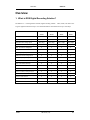
1. What is DRS Digital Recording Solution?
The DRS is a 4 - 16 analog channel network, digital recording solution. Video, Audio, and Text EventLogs are digitized and stored on/up to: two internal hard-drives and external drives up to 4 terrebyte.
DRS5004
DRS5008
DRS5016
DRS5116
series
series
series
series
Analog Video Channels
4
8
16
16
1 Channel Audio Record/Playback
Y
Y
Y
Y
Max 60ips
Max 60fps
Max 120fps
Max 240fps
30 / 25
30 / 25
30 / 25
30 / 25
Built–in software multiplexer
Y
Y
Y
Y
1/4/9/13/16 Ch Mode on Monitor/PC
Y
Y
Y
Y
4TB Storage Capacity IEEE 1394 HDD
Y
Y
Y
Y
ATM/POS Text Recording/Search
Y
Y
Y
Y
4/4
4/4
16/4
16/4
Built-in motion detection 64-division
Y
Y
Y
Y
IEEE 1394, Ethernet Back-up
Y
Y
Y
Y
RS232, RS485/422 PTZ Control
Y
Y
Y
Y
32bit True-Color Graphic OSD Menu
Y
Y
Y
Y
Dynamic IP (DHCP), Floating IP Support
Y
Y
Y
Y
IR Remote Controller/PTZ Control
Y
Y
Y
Y
Network Client Software
Y
Y
Y
Y
CCTV Monitor Output
1
1
1
2
Y–shelf
Y–shelf
Y–RM Kit
Y–RM Kit
NTSC/PAL Recording Speed
NTSC/PAL Realtime Monitoring
Sensor/Relay – Inputs/Outputs
19” Rackmountable
Wren
2003. 09. 06 (v 1.0)
10
Overview
DRS5116
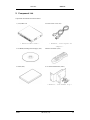
2. Component List
Unpack and check all the items shown below.
1. (1EA) DRS Unit
2. AC/DC Power Cord (1EA)
* DRS5004 / 5008 require DC
* DRS5116 model shown *
adaptor *
3. CD-ROM (Including DVR manager) (1EA)
4. Remote Controller (1EA)
5. Guide (2EA)
6. 19” RACK FIXING KIT (1SET)
* DRS5016 / 5116 models only *
Wren
2003. 09. 06 (v 1.0)
11
Overview
DRS5116
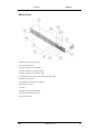
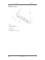
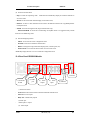
3. Description & Function
DRS5116 Front
(1) Power switch
(2) Function buttons
(3) LED
(4) I/O Port cover
(5) USB connector
(6) IEEE1394 connector
(7) Remote controller receiver
Wren
2003. 09. 06 (v 1.0)
12
Overview
DRS5116
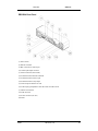
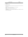
DRS5116 Rear
(8) BNC connector for video input
(9) AC power connector
(10) BNC connector for video output
(11) BNC connector for monitor A output
(12) BNC connector for monitor B output
(13) Terminal block for sensor, relay, and serial input/output
(14) IEEE1394 connecter
(15) Terminal block for RS232 & 422/485
(16) Ethernet connector
(17) GND
(18) RS232 connecter (9Pin D-Sub)
(19) Audio input/output connector
(20) S-VHS connector
Wren
2003. 09. 06 (v 1.0)
13
Overview
DRS5116
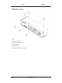
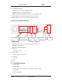
DRS5004 Front Panel
(1) LED
(2) IEEE1394 connecter
(3) Remote controller receiver
(4) USB connecter
(5) Function buttons
(6) Bracket fixing hole for rack mount
Wren
2003. 09. 06 (v 1.0)
14
Overview
DRS5116
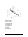
DRS5004 Rear Panel
(7) Power switch
(8) Ethernet connector
(9) BNC connector for Video input
(10) Audio input/output connector
(11) RS232 connecter (9Pin D-Sub)
(12) Terminal block for RS232 & 422/485
(13) Terminal block for Sensor input
(14) Terminal block for relay output
(15) Video output for Monitor or VCR
(16) Video input type/impedance select & remote controller switch
(17) IEEE1394 connecter
(18) USB connecter
(19) Power connector (DC12V)
(20) GND
Wren
2003. 09. 06 (v 1.0)
15
Overview
DRS5116
DRS5008 Front Panel
(1) LED
(2) IEEE1394 connecter
(3) Remote controller receiver
(4) USB connecter
(5) Function buttons
(6) Bracket fixing hole for rack mount
Wren
2003. 09. 06 (v 1.0)
16
Overview
DRS5116
DRS5008 Rear Panel
(7) Power switch
(8) Ethernet connector
(9) BNC connector for Video input
(10) Audio input / output connector
(11) RS232 connecter (9Pin D-Sub)
(12) Terminal block for RS232 & 422/485
(13) Terminal block for Sensor input
(14) Terminal block for Relay output
(15) Video output for Monitor or VCR
(16) Video input type/impedance select & remote controller switch
(17) IEEE1394 connecter
(18) USB connecter
(19) Power connector (DC12V)
(20) GND
Wren
2003. 09. 06 (v 1.0)
17
Installation and Connection
DRS5116
Installation and Connection
4. Connecting & Running
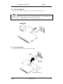
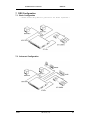
4.1. Connecting Camera
(1) Connect the CCTV camera to the DRS with the BNC cable as shown below.
<Note>
1.
The video type for all channels should be either NTSC or PAL.
2.
The DRS sets video signal’s impedance (75Ω) automatically. Impedance is set as 75Ω. When
connecting a device to video output, impedance will be “Hi-z” status.
3.
Video type (NTSC/PAL) should be changed prior to installing the DRS Unit.
video type, it is recommended to contact the closest local Wren distributor.
refer to “Appendix #2. Changing Video Type”.
To change the
When changing it,
Wren is not responsible for any service
warranty about a problem due to careless change.
Wren
2003. 09. 06 (v 1.0)
18
Installation and Connection
DRS5116
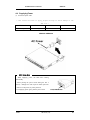
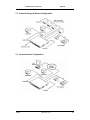
4.2. Connecting Monitor
(1) Connect the CCTV monitor to the DRS Unit with the BNC cable as shown below.
<Note>
The DRS5116 has two monitor output ports for A (Normal) and B (Spot).
When connecting only one
monitor, use monitor A. DRS5004/5008/5016 have single monitor outputs.
4.3. Connecting Audio
(1) Connect the audio signal to the DRS using the RCA cable.
Wren
2003. 09. 06 (v 1.0)
19
Installation and Connection
DRS5116
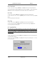
4.4. Supplying Power
(1) Connect the power cable.
* Care should be taken to apply proper voltage to avoid damage to the
DRS Unit *
DRS5004
DRS5008
DRS5016
DRS5116
12VDC supplied
12VDC supplied
110 ~ 220VAC
110 ~ 220VAC
DRS5016 & DRS5116
5000 Series Note
1. When supplying power, the DRS starts booting
automatically.
2. When pressing the power switch during the first 5
seconds, a dialogue box will require an admin password.
In order to cut off power, key in the password.
3. For supplying power again, push the power switch.
Wren
2003. 09. 06 (v 1.0)
20
Installation and Connection
DRS5116
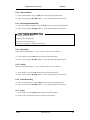
DRS5004 & DRS5008
(1) Connect the power cable.
(2) Turn on the power switch located on the DRS rear panel.
Wren
2003. 09. 06 (v 1.0)
21
Installation and Connection
DRS5116
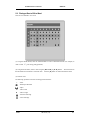
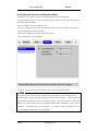
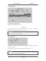
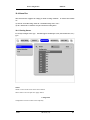
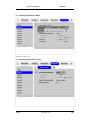
5. Running OSD Menu
5.1. Using Menu
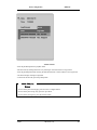
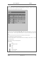
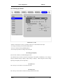
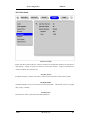
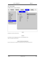
Press the [MENU] button to open the OSD Configuration menu.
(1) Main Menu
(2) Sub-Menu
(3) Setting Page
(1) Main Menu Tabs: The selected tab is shown in blue and the related sub-menus will be shown below
the tab.
To move to the previous/next Main Menu Tab, use the [◄◄/►►] arrow buttons.
To move to
a sub-menu, press the [ENTER] or [▼] buttons.
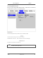
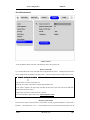
(2) Sub-Menu: The selected sub-menu is shown in blue and the related setting page will be shown to the
right of the sub-menu. Use the [▲/▼] arrow buttons to move within the sub-menu list. To move to the
setting page, press the [ENTER] button. To exit the setting page, press the [EXIT] button.
(3) Setting Page: The selected item is shown in gray.
[▲/▼] arrow buttons.
To move within each page, use the [◄◄/►►] or
Press the [ENTER] button to change the value of a setting.
value is a word, a dialogue box to edit the word will open.
When the setting value is a number, it should
be set with using the [◄◄/►►] or [▲/▼] arrow buttons.
button.
When the setting
After the value is set, press the [EXIT]
To exit the Setting Page, press the [EXIT] button.
(4) Help message: Related information for each menu/setting will be displayed here.
Wren
2003. 09. 06 (v 1.0)
22
Installation and Connection
DRS5116
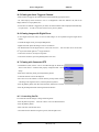
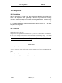
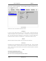
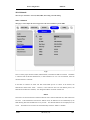
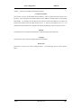
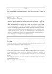
5.2. Dialogue Box to Edit a Word
There are two methods to set a word.
(1) Using the number button, enter the related numbers in order of horizontal/vertical. (For example, in
order to select “C”, press the [3] and [2] buttons)
(2) Using the arrow button, select a value using the [◄◄ / ►►] or [▲/▼] buttons.
the horizontal and vertical bar is a selected value.
The intersection of
Press the [►] button to confirm the selected value.
(3) Function word
The following symbols are used for executing specific functions:
9
: Enter
: Back Space & Delete
: Space
◄
: Move to left
►
: Move to right
: Previous Code Page
: Next Code Page
Wren
2003. 09. 06 (v 1.0)
23
Installation and Connection
DRS5116
6. Setting Remote Controller
6.1. Setting ID of DRS Digital Recording Solution
When controlling several DVRs with one remote controller, set Remote Control ID as follows:
(1) Press the [MENU] button.
(2) Select “System” using the [►►] button and press the [ENETR] or [▼] buttons.
(3) Select “Miscellaneous” from the sub-menu list using the [▼] button and press the [ENETR] button.
(4) Select “Remote Control ID,” and press the [ENETR] button.
(5) Select a value using the [◄◄/►►] buttons and press the [EXIT] button.
(6) Press the [EXIT] button to exit the Settings Page and return to the monitor mode.
<Note> Remote Control ID
Up to 16 DVRs can be controlled with a single remote controller.
Set the Remote Control ID to “Off”, if the remote controller is not being used.
Wren
2003. 09. 06 (v 1.0)
24
Installation and Connection
DRS5116
6.2. Selecting DRS
If several DVRs are set with unique ID numbers, they can be controlled with one remote controller.
To
select a specific (DRS), keep pressing the ID button on the remote controller until a buzzer sounds during
the first two seconds.
<Note>
Because the remote controller ID is sixteen, the DVR will correspond until the ID button is pressed
sixteen times.
6.3. Operable Range of Remote Controller
6.4. Loading the Batteries into Remote Controller
The remote controller requires two AAA-type batteries.
1. Remove the battery cover.
2. Taking care that the poles (+/-)
are correctly positioned.
3. Replace the battery cover.
<Note>
Batteries are not included as a packing accessory.
Wren
2003. 09. 06 (v 1.0)
25
Installation and Connection
DRS5116
7. DRS Configuration
7.1. Basic Configuration
* Camera/Sensor/Rely/Monitor Quantities are Model Dependant *
7.2. Advanced Configuration
Wren
2003. 09. 06 (v 1.0)
26
Installation and Connection
DRS5116
7.3. External Storage & Backup Configuration
7.4. Internet/Intranet Configuration
Wren
2003. 09. 06 (v 1.0)
27
Installation and Connection
8.
DRS5116
DRS Basic Setting
8.1. Viewing Image
After the initial start-up, images are displayed in a multi-split screen according to the connected channels
and specific model being installed. The following example is when four channels are connected.
<Note>
If a user password is set, a prompt for entering the password will appear.
Wren
2003. 09. 06 (v 1.0)
28
Installation and Connection
DRS5116
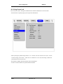
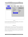
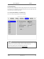
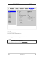
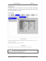
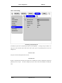
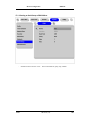
8.2. Setting Date & Time
(1) Press the [MENU] button, and select the “Quick Setup” tab.
(2) Select “Date/Time” and enter the Settings Page by pressing the [ENTER] button.
8.2.1. Time Zone
(1) Select the “Time Zone” and press the [ENTER] button to configure.
(2) Select a value using the [◄◄/►►] buttons and press the [EXIT] button when finished.
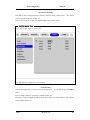
8.2.2. Daylight Saving
(1) “Daylight Saving Time” is only activated for time zones that use Daylight Savings.
If activated,
press the [ENTER] button to enter a new value.
(2) Select “On/Off” using the [◄◄/►►] buttons and press the [EXIT] button when finished.
8.2.3. Sync with NTP
In order to synchronize time with NTP (Network Time Protocol) server, select “On”.
(1) Select “Sync with NTP” using the [◄◄/►►] or the [▲/▼] buttons and press the [ENTER] button.
(2) Select “On/Off” using the [◄◄/►►] buttons and press the [EXIT] button.
Wren
2003. 09. 06 (v 1.0)
29
Installation and Connection
DRS5116
8.2.4. Time Format
(1) Select “Time Format” using the [◄◄/►►] or the [▲/▼] buttons and press the [ENTER] button.
(2) Two Time Formats are available; ‘MM/DD/YYYY’ and ‘YYYY/MM/DD’. Select a value using the
[▲/▼] buttons, and press the [EXIT] button when finished. (Default value is ‘MM/DD/YYYY’)
8.2.5. Date
(1) Select “Date” using the [◄◄/►►] or the [▲/▼] buttons and press the [ENTER] button.
(2) Select ‘MM’/‘DD’/‘YYYY’ using the [◄◄/►►] buttons, and select the value using the [▲/▼]
buttons.
(3) Press the [EXIT] button when finished.
8.2.6. Time
(1) Select “Time” using the [◄◄/►►] or the [▲/▼] buttons and press the [ENTER] button.
(2) Select ‘HH’/‘MM’ using the [◄◄/►►] buttons, and select the value using the [▲/▼] buttons.
(3) Press the [EXIT] button when finished.
8.2.7. Apply Date/Time
Most setting values are applied automatically, when exiting from the related menu page.
But
“Date” & “Time” settings are not applied automatically because they may critically affect the file
system of the recorded HDD. To apply Date/Time settings, confirm the settings with the [Apply
Date/Time] button.
(1) Select “Apply Date/Time” using the [◄◄/►►] or the [▲/▼] buttons and press the [ENTER] button.
A warning message will appear.
(2) Select “OK” using the [◄◄/►►] or the [▲/▼] buttons and press the [ENTER] button.
To cancel,
press the [EXIT] button.
Wren
2003. 09. 06 (v 1.0)
30
Installation and Connection
DRS5116
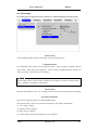
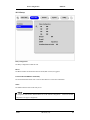
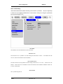
8.3. Setting Recording Condition
Recording conditions under the “Quick Setup” menu tab will apply the same values to all analog channels
1~16.
All settings are applied for 24 hours/day regardless of the values set for “Time Schedule” or
“Alarm Rec.”
(1) Press the [MENU] button, and select “Quick Setup.”
(2) Move to sub-menu by pressing the [ENTER] or the [▼] buttons.
(3) Select “Recording” using the [▲/▼] buttons and press the [ENTER] button.
8.3.1. Configuration Status
This function displays the recording configuration status.
menu, the “Quick Setup” will be shown.
When setting up through the “Quick Setup”
When setting up through the “Normal Rec.” or “Alarm Rec.,”
the “Custom Setup” will be shown.
<Note>
Only when all the DRS channels' normal recording conditions are set through 'Macro Setup' and
maintained, it is marked as 'Macro Setup'. Otherwise, it will be marked as 'Custom Setup'.
Wren
2003. 09. 06 (v 1.0)
31
Installation and Connection
DRS5116
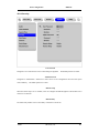
8.3.2. Channel Status
(1) Select “Channel Status” using the [▲/▼] buttons and press the [ENTER] button.
(2) Select a value using the [◄◄/►►] buttons.
Press the [EXIT] button when finished.
8.3.3. Recording Speed/Quality
(1) Select “Recording Speed/Quality” using the [▲/▼] buttons and press the [ENTER] button.
(2) Select a value using the [◄◄/►►] buttons.
Press the [EXIT] button when finished.
<Note> Recording Speed/Quality means
Low:Speed=1fps and Quality=Q5
Std.:Speed=5fps and Quality=Q5
High:Speed=15fps and Quality=Q5
Custom:Speed and Quality = Manually defined by User.
8.3.4. Speed (fps)
When “Recording Speed/Quality” is set as “Custom,” values can be set manually.
(1) Select “Speed” using the [▲/▼] buttons and press the [ENTER] button.
(2) Select a value using the [◄◄/►►] buttons.
Press the [EXIT] button when finished.
8.3.5. Quality
When “Recording Speed/Quality” is set as “Custom,” values can be set manually.
(1) Select “Quality” using the [▲/▼] buttons and press the [ENTER] button.
(2) Select a value using the [◄◄/►►] buttons.
Press the [EXIT] button when finished.
8.3.6. Audio Recording
(1) Select “Audio Recording” using the [▲/▼] buttons and press the [ENTER] button.
(2) Select a value using the [◄◄/►►] buttons.
Press the [EXIT] button when finished.
8.3.7. Apply
(1) Select “Apply” using the [▲/▼] buttons and press the [ENTER] button.
(2) Setting values are applied and the previous menu will be displayed.
Wren
2003. 09. 06 (v 1.0)
32
Installation and Connection
DRS5116
9. Connecting and Configuring DIO Ports
<Note> Wire Handling
Trimming Wire
When connecting a wire to a terminal block, follow the instructions below.
Note the different types of
wire that can be used.
Stranded Wire: Peel off the wiring cover
8~10mm and solder it.
The wire gage should
be AWG 22~26.
Solid Wire: Peel off the wiring cover 8~10mm
and solder it. The wire gage should be AWG
20~26.
Inserting & Removing Wire
To insert the wire, use a screwdriver as
shown in the diagram to the right.
Wren
2003. 09. 06 (v 1.0)
33
Installation and Connection
DRS5116
9.1. Connecting and Configuring Sensor
9.1.1. Specification
In order to run sensor input of DRS series normally, the following conditions are required:
Spec.
Input Ch.
16Ch. Photo coupler inputs *Model Dependant*
Input type
N.C. (Normal Close) / N.O. (Normal Open) type
Supported sensor
Dry contact
Connecting
Connecting the trimmed wire to terminal block
Available input pulse Min. 500ms
Performance range
Output current
Typical DC 12mA
9.1.2. Connecting Sensor Input
Connect S1 ~ S16 (Model Dependant) referring to the following.
connection.
It shows a dry contact
When connecting a non-dry contact type of sensor (e.g. Open collector output) please
contact Wren Technical Support team.
* DRS 5016/5116 Series Shown *
Wren
2003. 09. 06 (v 1.0)
34
Installation and Connection
DRS5116
9.1.3. Configuring Sensor at OSD Menu
* DRS5016 / 5116 Models *
(1) Press the [Menu] button, and select the “Alarm Source” among OSD menus.
(2) Select the “Sensor” menu and press the [Enter] button to move to the sub-menu.
9.1.3.1. Global
The “Global” is used for setting 16 sensors simultaneously to one of three types; Off/Normal Open
(NO)/Normal Close (NC).
(1) Select “Global” and set a type.
(2) Press the “Apply” button in order to confirm the setting value.
9.1.3.2. Configuration
The Configuration is used for setting 16 sensors separately.
Select and set each sensor.
(1) Select “Configuration” and press the [Enter] button.
(2) Select a sensor (S1 ~ S16) and set its type.
(3) Press the [Exit] button after setting.
Wren
2003. 09. 06 (v 1.0)
35
Installation and Connection
DRS5116
* DRS5004 Model *
(1) After a sensor is connected, it can be activated through the OSD Configuration menu.
(2)
Select the sensor number (S1, S2, etc.) and press the [Enter] button to configure.
[◄◄/►►] buttons to select “On” or “Off.”
Use the
Press the [EXIT] button when finished.
(3) When activated, the “Pre/Post Alarm” function will cause the HVR-04E to record images at the
specified speed and quality for a length of time before and/or after the sensor is triggered.
*DRS5008 Model *
Wren
2003. 09. 06 (v 1.0)
36
Installation and Connection
DRS5116
(1) After a sensor is connected, it can be activated through the OSD Configuration menu.
(2) Select the sensor number (S1, S2, etc.) and press the [Enter] button to configure.
[◄◄/►►] buttons to select “On” or “Off.”
Use the
Press the [EXIT] button when finished.
(3) When activated, the “Pre/Post Alarm” function will cause the HVR-08E to record images at the
specified speed and quality for a length of time before and/or after the sensor is triggered.
<Note>
1. This menu is used to set sensor using and sensor type.
However, recording by sensor input and
relay output should be set in another menu.
2. For recording setting by sensor input, refer to the “Alarm Rec.” part of the “ DRS Programming
Guide”.
3. For relay output, refer to the “Alarm Act.” part of the “DRS Programming Guide”.
Wren
2003. 09. 06 (v 1.0)
37
Installation and Connection
DRS5116
9.2. Connecting & Configuring Relay Out
9.2.1. Specifications
In order to operate the relay outputs of the DRS Digital Recording Solution (all models) normally, the
following conditions are required.
Spec.
Output Ch.
4Ch. Relay differential outputs
Output type
Dry Contact
Connecting type
Connect the trimmed wire to the screwless terminal block
DC
24V DC, 1.25A, 30W
Rating
125V DC, 0.24A, 30W
AC
125V AC, 0.5A, 62.5VA
9.2.2. Connecting Relay Out
When connecting R1 ~ R4 refer to the following diagram.
This diagram shows connection to a warning
light.
Wren
2003. 09. 06 (v 1.0)
38
Installation and Connection
DRS5116
9.2.3. Configuring Relay Out at OSD Menu
Each relay can be synchronized with a sensor input or with motion detection for each of the four-time
schedules: (Weekday/(Day), Weekday/(Night), Weekend/(Day), Weekend/(Night)).
Relays can also be
controlled locally by pressing the [SEARCH/RELAY] button followed by the relay number (1-4).
Relays can also be controlled remotely through the “DVR Manager software.”
* DRS5004 Model *
* DRS5008 Models *
Wren
2003. 09. 06 (v 1.0)
39
Installation and Connection
DRS5116
* DRS5016/5116 Models *
<Note>
(1) For detailed information for setting, please refer to the “ DRS Programming Guide”..
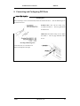
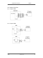
9.3. Connecting Serial Port
9.3.1. Configuring Serial Ports for Pan/Tilt/Zoom
The DRS series units have most major PTZ protocols already pre-programmed.
models not supported can still be controlled using the Transparent Protocol.
Certain makes and
For a list of supported
protocols, refer to the list on the OSD Configuration menu.
The following figure shows how to connect the PTZ camera to RS485 (COM2).
When using another
serial port, connect it with referring to each connection diagram below.
Wren
2003. 09. 06 (v 1.0)
40
Installation and Connection
DRS5116
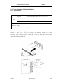
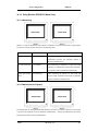
9.3.2. Diagrams of Serial Ports
9.3.2.1. Diagram of COM1
9.3.2.2. Diagram of COM2
Wren
2003. 09. 06 (v 1.0)
41
Installation and Connection
DRS5116
9.3.2.3. Diagram of COM3
9.3.2.4. Diagram of COM4
9.3.3. View of COM3/COM4 Serial Ports
Wren
2003. 09. 06 (v 1.0)
42
Installation and Connection
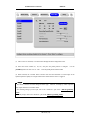
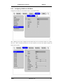
9.3.4.
DRS5116
Configuring COM Port at OSD Menu
Configure PTZ COM ports and available modes at “System/Serial Setup”.
After completing serial setup, configure the base address and port for each channel under the “Camera”
menu tab.
When connecting PTZ devices to several cameras, be sure the base address matches the
address for the camera.
Wren
2003. 09. 06 (v 1.0)
43
Installation and Connection
DRS5116
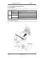
9.4. Connecting External Device with Serial Port
9.4.1. Connecting Text Input Device (ATM/POS/Access Control)
In addition to images, the DRS units can record text data received from POS/ATM through the
COM1/RS232 serial port.
Connect to COM1/RS232 (9pin D-Sub) of the DRS5116, and configure the “Serial Setup” sub-menu
under the “System” tab and “Text” sub-menu under the “Alarm Source” tab.
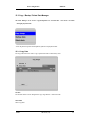
9.4.2. Configuring Serial Setup (COM1) at OSD Menu
(1) Set the “System” in OSD menus, and move to the “Serial Setup” menu.
(2) Select COM1 in the “Serial Setup”, set device as “Text”.
(3) Set Baud Rate/Parity/Stop bit/Data bit with referring to manual of the connected external device.
Wren
2003. 09. 06 (v 1.0)
44
Installation and Connection
DRS5116
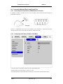
9.4.3. Configuring Text
(1) Select the “Alarm Source” menu among OSD menus.
(2) Select the “Text”, and set each value.
<Note>
Before installing any external device, consult with the local distributor. Some external devices may not
be compatible with the DVR.
Wren
2003. 09. 06 (v 1.0)
45
Installation and Connection
DRS5116
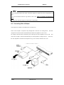
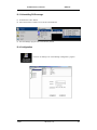
9.5. Connecting USB Device
The USB port can be used to copy up to one minute of images to a USB Flash memory disk. When
connecting a USB device, do not exceed the rated values of the USB device.
USB Spec.
Available Device
Output Voltage/Current
Ver 1.1 (Max 12M bps)
USB Memory Stick,
Max. 200mA per DC 5V Port
<Note>
The disk should be formatted with FAT32 type.
If properly connected, the disk is recognized automatically as shown in the following picture.
To copy
images, the process is as follows: Set copy range (up to 1 minute) Æ Select drive Æ Copy (press “Start”).
Wren
2003. 09. 06 (v 1.0)
46
Installation and Connection
DRS5116
<Note>
1. The USB Flash products that require a Windows program to operate may not be recognized by the
DVR.
2. For more information about the copy function, refer to the “ DRS Programming and Maintenance
Guide”.
3. Contact Wren Technical Support for Flash Product Compatibility.
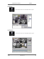
9.6. Connecting Video In/Output
Video outputs are available on the DRS5016/5116 models only.
DVR's video in/output is composed of loop through BNC connectors in an analog format.
The DVR
recognizes the connection status and automatically matches the impedance to 75Ω or Hi-z
For example, when the DVR is connected by only video input, the video impedance is set as 75Ω. And
when video in/output is connected simultaneously, the video impedance is changed as Hi-z.
In this case,
the video impedance of external video input device (e.g CCTV monitor) should be set as 75Ω.
* DRS5116 Model Shown *
Wren
2003. 09. 06 (v 1.0)
47
Installation and Connection
DRS5116
10. Connecting External Storage
10.1. IEEE1394 Port
DRS5116 series have two IEEE1394 ports for external storage device interface.
With them, the DRS
series can expand storage capacity up to 4TB.
<Note>
Some IEEE1394 bays may not be recognized by the DRS series.
Before purchasing, consult the local
distributor.
10.2. Connecting IEEE1394 Device
When using FireWire supported by external HDD, hard drive bays can be connected to one port in the
front panel or one port in the rear panel.
The DRS series does not supply power to the hard drive bay;
therefore only bays that use external power can be used.
<Note>
The DRS series detect external HDD, even though DRS series run. If not, it is recommended to
connect as follows.
Wren
1.
Power off the DRS.
2.
Connect external HDD to IEEE1394 port.
3.
Power on external device.
4.
Power on the DRS.
2003. 09. 06 (v 1.0)
48
Installation and Connection
DRS5116
11. Network Monitoring & Managing
The DRS can be accessed, controlled, and managed from a remote site via Internet/Intranet.
11.1. Connecting Ethernet
(1) Turn off the DRS power switch.
(2) Connect the DRS to hub with Ethernet cable.
(3) Turn on the DRS power switch.
<Note>
1. Supply power to the DRS after connecting Ethernet cable to protect against electrical damage
2. Check cable connection status.
3. Check LED on the DRS rear panel after supplying power.
Wren
2003. 09. 06 (v 1.0)
49
Installation and Connection
DRS5116
11.2. Configuring DRS Network Information
The following description is on based on Ethernet connection.
For more detailed information on the
Network Settings Page, please refer to the “ DRS Programming and Maintetnance Guide”.
(1) Press the [MENU] button.
(2) Select “System” using the [◄◄/►►] buttons and press the [ENTER] button.
(3) Select “Network” using the [▲/▼] buttons and press the [ENTER] button.
(4) Select “IP Addr” using the [▲/▼] buttons and press the [ENTER] button.
(5) Press the [EXIT] button after entering the IP address in the dialogue box.
(6) Select “Net Mask” using the [▲/▼] buttons and press the [ENTER] button.
(7) Press the [EXIT] button after entering Net Mask in the dialogue box.
(8) Select “Gateway” using the [▲/▼] buttons and press the [ENTER] button.
(9) Press the [EXIT] button after entering Gateway in the dialogue box.
(10) Select “DNS” using the [▲/▼] buttons and press the [ENTER] button.
(11) Press the [EXIT] button after entering DNS in the dialogue box.
(12) Press the [EXIT] button to exit the page.
Wren
2003. 09. 06 (v 1.0)
50
Installation and Connection
DRS5116
12. Using DVR Manager
12.1. PC System Requirements for running DVR Manager
Minimal Requirements
Recommended Requirements
CPU
P-Ⅲ 600MHz or above
P-Ⅲ 1GHz or above
RAM
128 MB or above
256 MB or above
VGA
16 MB or above
32 MB or above
OS
Windows 2000/XP
Windows 2000/XP
Resolution
1024 X 768 pixels or above
1024 X 768 pixels or above
Network
100 Base TX Fast Ethernet
100 Base TX Fast Ethernet
12.2. Installing DVR Manager
(1) Insert the Setup CD-ROM into the CD-ROM drive of the administrator’s PC.
(2) Doubleclick the DVR manager setup file.
Shield Wizard will be automatically installed.
(3) Click the “I Agree” button to accept the license agreement
Wren
2003. 09. 06 (v 1.0)
51
Installation and Connection
DRS5116
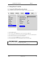
(4) Select which components to install and press the “Next” button.
(5) Browse and choose a directory if the default directory is not preferred.
Click the “Install” button,
after selecting a directory to install.
(6) Click the “Close” button after the DVR Manager program is installed successfully.
Wren
2003. 09. 06 (v 1.0)
52
Installation and Connection
DRS5116
12.3. Uninstalling DVR manager
(1) Click Windows “Start” Button.
(2) Select and click the ‘Uninstall’ icon to run the Uninstall Shield.
(3) The DVR Manager program will be automatically deleted.
12.4. Configstation
Click icon on desktop to run “DVR Manager Configstation” program.
Wren
2003. 09. 06 (v 1.0)
53
Installation and Connection
DRS5116
12.5. Monitor
Click the related icon and run the “DVR Manager Monitor” program.
12.6. Playback
Click the related icon and run the “DVR Manager Playback” program.
Wren
2003. 09. 06 (v 1.0)
54
Installation and Connection
DRS5116
Section 2
DRS Digital Recording Solution
Programming and Maintenance
(v 1.0)
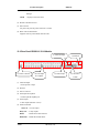
13. Product Description
13.1. Front Panel DRS5016 / 5116 Models
(2) Remote
(1) LED
Controller Receiver
(3) Power Switch
(4) IEEE 1394 &
(5) Function selection
(6) Channel
(7) Menu/Direction
USB Interface
button
Selection Button
Button
(1) LED
PWR : Displays power status.
NET
When lit, power is supplied.
: Displays the status of Ethernet connection and rate of communication.
When blinking,
data being transmitted or received over the Ethernet.
REC
: Displays image recording status. The rate of blinking indicates the speed of recording.
(i.e. When blinking rapidly, HVR-16E is recording at a high rate; when blinking slowly,
the HVR-16E is recording at a lower rate.)
PLAY
: Displays playback status.
The rate of blinking indicates the speed of playback. (i.e.
When blinking rapidly, HVR-16E is playing back at a high rate; when blinking slowly, the
HVR-16E is playing back at a lower rate.)
Wren
Its status is the same when using the DVR
2003. 09. 06 (v 1.0)
55
Product Description
DRS5116
manager.
LOCK
: Displays screen lock status
(2) Remote Controller Receiver
(3) Power Switch
For power off, press the power switch for 5 seconds.
(4) IEEE 1394 & USB Interface
Supports each one port for IEEE1394 and USB
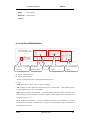
13.2. Rear Panel DRS5016 / 5116 Models
(3) Power Connector
(4) Video Input
(1) Audio In/Output
(2) Ethernet
(5) Video Output
(6) Serial Port
& Loopback
& DIO
(1) Audio In/Output
1 audio input & 1 output
(2) Ehternet
(3) Power Connector
(4) Video Input & Loopback
16 video inputs & loopback port
(5) Video Output
2 video outputs (Monitor or VCR)
(6) Serial Port & DIO
Sensor In : 16 sensor inputs
Relay Out
: 4 relay outputs
RS232
: RS232 9Pin D-Sub connector
RS422/485 : RS422/485 terminal block
Wren
2003. 09. 06 (v 1.0)
56
Product Description
RS232
DRS5116
: RJ45 connector
RS422/485 : RJ45 connector
IEE1394
13.3. Front Panel DRS5008 Model
(1) Remote Controller
Receiver
(3) LED
(2) Channel
Selection Button
(4) Function selection
button
(5) Direction/Replay
Button
(5) Remote Controller Receiver
(6) Channel Selection Button
- To select a video input channel in monitoring and playback mode
(7) LED
- PWR: Displays power status.
When lit, power is supplied.
- NET: Displays the status of Ethernet connection and rate of communication.
When blinking, data is
being transmitted or received over the Ethernet.
- REC: Displays the image recording status.
The rate of blinking indicates the speed of recording. (i.e.
When blinking rapidly, HVR-08E is recording at a high rate; when blinking slowly, the HVR-08E is
recording at a lower rate.)
- PLAY: Displays playback status.
The rate of blinking indicates the speed of playback. (i.e. When
blinking rapidly, HVR-08E is playing back at a high rate; when blinking slowly, the HVR-08E is
playing back at a lower rate.)
Wren
2003. 09. 06 (v 1.0)
57
Product Description
DRS5116
(8) Function selection button
- SEQ: To select the sequencing mode.
HVR-08E will automatically display all connected channels in
successive order.
- MULTI: To select the multi-channel display (4-9-divided screen).
- SELECT: To select a video channel for PTZ control in the Monitor mode and for Copy/Backup/Delete
in Playback mode
- ZOOM: To activate the digital zoom (single channel mode only).
RELAY/SEARCH: To search the recorded image in Playback mode or to toggle the Relay On/Off
function in the Monitoring mode.
(9) Direction/Replaying Button
-
MENU: To set PTZ and access Configuration menu.
-
ENTER: To enter and confirm the selected menu.
-
HELP: To change the image information display (Date, Transfer speed, etc).
-
EXIT/LOCK: To exit from the selected menu or lock current screen.
Arrow key: Replay function or to move inside the Configuration menu
13.4. Rear Panel DRS5008 Models
(6) Power
(1) Serial Port
(2) Audio
& DIO
port
(3) Video
(4) Video
Output
Input
(5) Ethernet
(1 )Serial Port & DIO
-
Serial: RS232 9Pin D-Sub Connector & RS232/422/485 terminal block
-
Sensor In: 4 sensor inputs
-
Relay Out: 4 Alarm Relay outputs
(2) Audio port
-
1 audio input & 1 output
(4) Video Output
Wren
2003. 09. 06 (v 1.0)
58
Product Description
-
DRS5116
1 monitor output & 1 VCR output
(5) Video Input
-
8 video inputs
(7) Ethernet
(8) Power
13.5. Front Panel DRS5004 Series Models
(3) LED
(1) Remote
(2) Channel
Controller Receiver
Selection Button
(4) Function
(5) Direction/Replay
selection button
Button
(1) Remote Controller Receiver
(2) Channel Selection Button
-
To select video input channel in monitoring and playback mode
(3) LED
-
PWR: Displays power status.
When lit, power is supplied.
-
NET: Displays the status of Ethernet connection and rate of communication.
When blinking, data
being transmitted or received over the Ethernet.
-
REC: Displays image recording status.
The rate of blinking indicates the speed of recording. (i.e.
When blinking rapidly, HVR-04E is recording at a high rate; when blinking slowly, the HVR-04E is
recording at a lower rate.)
-
PLAY: Displays playback status.
The rate of blinking indicates the speed of playback. (i.e. When
blinking rapidly, HVR-04E is playing back at a high rate; when blinking slowly, the HVR-04E is
playing back at a lower rate.)
Wren
2003. 09. 06 (v 1.0)
59
Product Description
-
DRS5116
ALARM: 1~4
(4) Function selection button
-
SEQ: To select the sequencing mode. HVR-04E will automatically display all connected channels in
successive order.
-
MULTI: To select the multi-channel display (4-9-16-13 divided screen).
-
SELECT: To select video channel for PTZ control.
-
ZOOM: To activate the digital zoom (single channel mode only).
-
SEARCH/RELAY: To search the recorded image in Playback mode or to toggle the Relay On/Off
function in the Monitoring mode
Wren
2003. 09. 06 (v 1.0)
60
Product Description
DRS5116
(5) Direction/Replaying Button
-
MENU: To set PTZ and access Configuration menu.
-
ENTER: To enter and confirm the selected menu.
-
HELP: To change the image information display (Date, Transfer speed, etc).
-
EXIT/LOCK: To exit form the selected menu or lock current screen.
Arrow key: Replay function or to move inside the Configuration menu.
13.6. Rear Panel DRS5004 Models
(1) Serial Port
(2) Audio port
& DIO
(3) Video
(4) Video (5) Ethernet
Output
Input
(6) Power
(1) Serial Port & DIO
-
Serial: RS232 9Pin D-Sub Connector & RS232/422/485 terminal block
-
Sensor In: 4 sensor inputs
-
Relay Out: 4 Alarm Relay outputs
(2) Audio port
-
1 audio input & 1 output
(3) Video Output
-
1 monitor output & 1 VCR output
(4) Video Input
-
4 video inputs
(5) Ethernet
(6) Power
13.7. Installation Summary
- Connect Camera
- Connect Monitor
- Connect Ethernet (This is optional to view an image on a remote location)
- Connect Audio
- Connect Power & Run
Wren
2003. 09. 06 (v 1.0)
61
Basic Configuration
DRS5116
Basic Configuration
14. Monitoring
Once power is applied to the DRS Digital Recording Solution, all connected channels will be displayed
by the 4/8/16 split monitoring mode.
The following steps apply for all DRS Digital Recording
Solution’s monitoring menus.
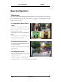
14.1. Viewing Basic Screen (QuadSplit)
- Insert the AC cord’s plug in a wall outlet, and
apply power to the unit. The LED will come on
and the DRS will start booting.
- After start-up, the basic screen (quad/split) is
displayed.
- If user password is set, a dialogue box for
entering the password will appear.
14.2. Viewing Single Full Screen
- Press the desired channel number button on the
front panel of the DRS.
- To return to the multi-view screen, press the
[MULTI] button.
14.3. Viewing Multi Screen
- Press the [MULTI] button to view several
channels simultaneously.
- To change the split screen configuration, press
the [MULTI] button.
Wren
4 / 9 / 16 / 13 split screens will be displayed.
2003. 09. 06 (v 1.0)
62
Basic Configuration
DRS5116
14.4. Viewing all Channels with Sequence Mode
- All channels can be viewed in successive order automatically using the [SEQ] button.
- Press the [MENU] button on the front panel to set-up the sequential cycle. (The default value is 3
seconds per channel for display.)
- Select the “Monitor” tab of Configuration menu.
- Move to “Configuration” below “Monitor” using the down arrow button on the HVR-16E front panel.
- Press the [ENTER] button to enter the menu.
- Select “Seq. Switching(sec)” and press the [ENTER] button.
- Set any value between 1 and 60 seconds.
- In order to move to the sequence mode from any viewer mode, press the [SEQ] button.
<Note>
The sequence mode can run only when connected and activated cameras are more than split screen.
With the single full screen mode, there should be two or more activated cameras.
With the quad-split
screen mode, there should be five or more activated cameras. With the 9-split screen mode, there
should be ten or more activated cameras. (SEQUENCE MODE ONLY SUPPORTS 4- AND 9- SPLIT
SCREENS).
The channel order cannot be changed.
For example, with the quad-split screen, Ch.
1/2/3/4 are displayed and then Ch.5/6/7/8 are displayed.
- To end sequence function, press the [SEQ] button
Wren
2003. 09. 06 (v 1.0)
63
Basic Configuration
DRS5116
14.5. Viewing an Alarm Triggered Channel
- When an alarm is triggered, the related channel will automatically pop-up full screen.
- Set ‘Alarm Pop-up Screen’ function to “On” in “Configuration” under the “Monitor” tab, and set the
display duration in “Pop-up Hold (sec)”
- If more than one channel is triggered by an alarm, the related channels will be displayed simultaneously
in a split-screen.
In order to move the current screen, press any button.
14.6. Viewing Images with Digital Zoom
- In the Single Full Screen mode, live and recorded images can be expanded using the Digital Zoom
feature.
- To enable the digital zoom, press the [ZOOM] button.
- Digital Zoom will expand the image to twice its normal size.
- The default location of the digital zoom is in the center of screen.
th
The zoom box can be moved each
th
10 step to the left and right and 7 step up and down.
- To move the zoom box, use the [Arrow] button.
- To cancel the zoom box, press the [ZOOM] button once more.
14.7. Viewing with Connected PTZ
- Pan/Tilt/Zoom (PTZ) devices can be controlled through the HVR-16E
when a PTZ device is connected and properly configured under “Serial
Setup.”
- While in the monitoring mode, press the [SELECT] button.
- A Channel selection icon will be displayed.
- Move the icon to the channel to control with the [Arrow] button. (When
controlling in the single full screen, select the [SELECT] button.)
- Press the [MENU] button, then PTZ menu (Pan/Tilt, Zoom/Focus, Load Preset, Save Preset) will appear.
- Press the [ENTER] button after selecting the desired function
14.7.1. Controlling Pan/Tilt
To control Pan and Tilt during live image monitoring mode:
- Press the [SELECT] button.
Move the “Select” icon to the desired channel.
- Press the [MENU] button.
- Select ‘Pan/Tilt’ from the PTZ menu.
- Control Pan and Tilt function using the up, down, left and right arrows.
Wren
2003. 09. 06 (v 1.0)
64
Basic Configuration
DRS5116
14.7.2. Controlling Zoom/Focus
To control Zoom and Focus during live image monitoring mode:
- Press the [SELECT] button.
Move the “Select” icon to the desired channel.
- Press the [MENU] button.
- Select ‘Zoom/Focus’ from the PTZ Menu.
- Control Zoom and Focus functions using the up, down, left and right arrows of front panel.
14.7.3. Using Load Preset
To load preset for dome camera during live monitoring mode:
- Press the [SELECT] button.
Move the “Select” icon to the desired channel.
- Press the [MENU] button.
- Select ‘Load Preset’ from the PTZ Menu.
- Press the number button for desired preset on the front panel.
14.7.4. Using Save Preset
To set a new preset point for dome camera during live monitoring mode:
- Move dome camera to the desired position using the ‘Pan/Tilt’ and ‘Zoom/Focus’ menus.
- Press the [SELECT] button.
- Press the [MENU] button.
- Select ‘Save Preset’ from the PTZ Menu.
- Designate a number for the preset position by pressing a number button on the front panel.
14.8. Using Relay
To set relay on/off. (HVR-16E supports four relay outputs):
- Press the [ACK/RELAY] button.
- The icon “Relay On” shows on the screen.
- Press the relay number button between 1 and 4, and then the related relay out signal will be transmitted.
- In order to set relay off, press the [ACK/RELAY] button again.
- The “Relay On” will show because the relay keeps being set as on.
- Press the [ACK/RELAY] button again, and the icon “Relay Off” will show.
Wren
2003. 09. 06 (v 1.0)
65
Basic Configuration
DRS5116
14.9. Using Screen Lock
The screen lock is used to lock againt unauthorized users when the administrator is not at his desk.
- For this function to operate properly, the user password should be set.
- While pressing the [EXIT/LOCK] button for 2~3 seconds, the Lock mode will run with a “Screen
Locked” message on the screen.
When the “User Password” is set to off, the message “Enable user
password first” shows on the screen.
- If lock mode is enabled, all function buttons will be unoperational.
- In order to cancel lock mode, user password must be entered.
Wren
2003. 09. 06 (v 1.0)
66
Basic Configuration
DRS5116
14.10. Using Monitor B DRS5116 Model Only
14.10.1.Monitoring
Monitor A is used for monitoring multi-channels, and Monitor B is used for monitoring a single-channel.
The user can monitor channels as shown in the following tables.
Monitor A
16-split screen mode
Monitor B
Remarks
1ch monitoring
When monitoring 16 channels in Monitor A,
administrator monitors the important channel in
Monitor B simultaneously.
13-split screen mode
User sequence
When monitoring 12 channels by 13-split screen mode
in Monitor A, administrator monitors four channels by
user sequence mode in Monitor B simultaneously.
Quad split sequence 1ch monitoring
When monitoring all channels by each quad split
mode
sequence mode, administrator monitors the important
channel in Monitor B simultaneously.
14.10.2.Multi-Channels Playback
The administrator can search/playback multi-channels by the split screen mode in Monitor A, and monitor
1 channel by the single full screen in Monitor B simultaneously. Namely, the administrator can monitor
and playback with two monitors simultaneously.
Wren
2003. 09. 06 (v 1.0)
67
Basic Configuration
DRS5116
14.10.3.1 Ch Playback
The administrator can monitor multi-cahnnels by split screen mode in Monitor A, and search/playback
one channel by single full screen in Monitor B simultaneously.
15. Playback
Playback is used to replay recorded images in full screen or a split screen (4/9/16) mode depending on
the model installed.
15.1. Playback via Various Mode
15.1.1. Playback via Basic Screen (Full Screen)
- Press the Play [►] button in the monitoring mode.
- The Play [►] button will begin playback of the last 30 seconds of recorded video at 1X speed.
<Note>
When pressing the play button in the multi-monitoring mode, channel 1 is always the channel displayed.
More specifically, images recorded on Channel 1 during the last 30 seconds are always displayed.
However, pressing the playback button in the single-channel monitoring mode will display the selected
channel.
To display another channel, press the corresponding number button on the front of the DRS
Unit.
15.1.2. Playback via a Split Screen (4/9/16)
- Press the [MULTI] button during basic (single-channel) playback mode.
- Channels 1 to 4 will be displayed in the quad-split screen.
- To display a single channel, press the corresponding number button on the front of the DRS.
Wren
2003. 09. 06 (v 1.0)
68
Basic Configuration
DRS5116
15.1.3. Playback Ch5 to Ch16 via Quad-Split Screen
- Press the [SELECT] button in the quad-split mode.
- Select a split position.
- When a channel number is selected, the related image is played in the position.
15.1.4. Playback with Digital Zoom
- Press the [ZOOM] button during the basic (single-channel) playback mode.
- The Digital Zoom will expand the image to twice its normal size.
- The default location of the digital zoom is in the center of screen.
th
The zoom box can be moved each
th
10 step to the left and the right and 7 step up and down.
- To move the zoom box, use the [Arrow] button.
- To cancel the zoom box, press the [ZOOM] button once more.
15.1.5. Various Playback Modes
► (PLAY)
: To begin playback mode and replay at 1x speed.
After pressing PAUSE
(▌▌), PLAY will advance recorded images frame by frame.
■ (STOP)
: To stop replaying
▌▌ (PAUSE)
: To pause replaying
►► (FFW)
: Each press of the button will increase playback speed gradually (x1, x2, x4,
x8, x16)
◄◄ (FRW)
: Each press of the button will increase playback speed gradually (x1, x2, x4,
x8, x16)
STEP FORWARD
: Pressing the [►, PLAY] or [►►, FFW] buttons from the PAUSE status,
will replay an image frame by frame.
In order to go back to the normal
playback mode, press the [■, STOP] button, then press the [►, PLAY] or
[►►, FFW] buttons.
STEP REWIND
: Pressing the [◄◄, FRW] button from the PAUSE status, will replay an
image frame by frame.
In order to go back to the normal playback mode,
press the [■, STOP] button then press the [►, PLAY] or [►►, FFW]
buttons.
15.2. Using Search Mode
The Search mode is used to search and play specific data directly in the playback mode. Data can be
searched by specific Time and Date or by the Event Log browser.
Wren
2003. 09. 06 (v 1.0)
69
Basic Configuration
DRS5116
<Button control>
- Press the [SEARCH] button in playback mode.
- Search for data by entering Date/Time or by selecting an event from the Event Log browser.
- Press the [ENTER] button after entering the desired Date/Time or select from the Event Log browser.
- The selected images will begin to playback.
- To exit from search mode, press the [EXIT] button.
<Note> Using Log
Browser
1. To move to the previous/next page, press the "Left" or "Right" buttons.
2. To move to the previous log entry, press the "Up" button.
3. To move to the next log entry, press the "Down" button.
Wren
2003. 09. 06 (v 1.0)
70
Basic Configuration
DRS5116
15.3. Copy / Backup / Delete Data Manager
The Data Manager can be used to copy/backup/delete the recorded data. This menu is activated
duringthe playback mode.
- Press the [SELECT] button and the [MENU] button in the playback mode.
15.3.1. Copy Data
The Copy Data function is used to copy a specific data with a USB memory stick.
Seconds
The Seconds menu is used to designate the copy range between 1 and 60 seconds.
Select Disk
Select copy disk.
Wren
2003. 09. 06 (v 1.0)
71
Basic Configuration
DRS5116
15.3.2. Backup Data
Start Date & Time / End Date & Time
This menu is used to designate a backup range.
Select Disk
The Select Disk menu is used to select which storage will be used as a backup device.
To change the
disk status, use the “Disk Manager” menu under the “System” tab.
<Note>
The Backup Manager does not support USB devices.
The Backup Manager will ONLY work with
devices connected through IEEE1394/FireWire ports.
15.3.3. Delete Data
The Delect File is used to delete a specific file range from the current recording HDD. This menu does
not affect the backup disk.
The beginning of the range is always the beginning of the recording on the HDD.
<Note>
The block unit of the DVR’s file system is 64MB, and the DVR deletes by block.
Therefore, the data
may not be deleted correctly, even though time is designated.
Wren
2003. 09. 06 (v 1.0)
72
Basic Configuration
DRS5116
16. Configuration
16.1. Quick Setup
There are three menus for recording setup; Quick Setup, Normal Recording and Alarm Recording
menus in the Configuration Menu.
Quick Setup is the easiest set-up,which activates all analog
cameras (4 ~16 Model Dependant) to record with the same settings and conditions. Normal recording
is the standard recording setting and can be customized based on time and channel. Alarm recording
is the recording schedule based on alarm conditions (Motion Detection, Sensors, etc.) Also, Quick
Setup has a time setting menu.
16.1.1. Date/Time
At the time of factory installation, the time zone will be set as “UTC 00:00 Dublin”.
Set the time to the local time zone.
Changing the DRS Digital Recording Solution time may cause time conflict with the recorded images.
In this case, it is strongly recommended to re-format the hard drives after making changes.
be taken to have the correct time programmed prior to rerecording the video.
Care should
Setting Daylight Savings
time after installation will not affect the recorded images.
<Button control>
- Press the [MENU] button on the DRS front panel.
- Move to the “Quick Setup” menu (the first tab on the Configuration menu).
- Move to “Date/Time” below “Quick Setup” using the downward arrow button on the DRS5116 front
panel.
- Press the [ENTER] button on the DRS front panel.
- Set time (the following picture will be displayed when setting time menu).
Wren
2003. 09. 06 (v 1.0)
73
Basic Configuration
DRS5116
- In order to access each menu, press the [ENTER] button after selecting it with the
upward/downward arrow buttons on the DRS front panel.
Time Zone
Set the time zone using the left/right arrow button on the DRS front panel. Every time you press the
left/right arrow button, the time zone will change.
Select the desired time zone.
To move to the
previous menu, press the [EXIT] button on the DRS front panel.
Daylight Saving
The Daylight Savings option is linked to the time zone.
zones that use Daylight Savings.
Daylight Savings is only activated for time
For example, selecting GMT – 7:00 Arizona will disable the option for
Daylight Savings because Daylight Savings is not used in Arizona.
Zone” menu.
This menu is linked with the “Time
Namely, if selecting a daylight saving area in the time zone, this menu will be activated.
Oppositely, if the selected time zone is not enforced, it will not be used.
It is based on MS Windows.
So this menu is used for setting whether you apply ON/OFF (using the left/right arrow buttons on the
DRS front panel) in the daylight saving area.
Wren
2003. 09. 06 (v 1.0)
74
Basic Configuration
DRS5116
Sync with NTP
It is to synchronize time with NTP (Network Time Protocol) server.
<Note>
For more detailed information about the NTP setting, please refer to the “Network Configuration”
(System Æ Network Æ NTP Settings).
Time Format
Set the time format between “MM/DD/YYYY” and “YYYY/MM/DD” using the the left/right arrow
buttons on the DRS front panel.
Date/Time
Set date and time. To move from Month to Day to Year/Hour to Minute, use the left/right arrow buttons.
To select each month, each day, etc, use the up/down arrow buttons.
Apply Date/Time
Press the {Apply Date/Time} button to confirm the above settings.
the possibility of time conflict with recorded images.
A window will pop-up warning of
It is strongly recommended to format the HDD
after making changes to the time menu.
<Note>
Most setting values are applied automatically, when exiting from the related menu page.
But “Date” &
“Time” settings are not applied automatically because they may critically affect the file system of the
recorded HDD.
Wren
To apply Date/Time settings, confirm settings with the [Apply Date/Time] button.
2003. 09. 06 (v 1.0)
75
Basic Configuration
DRS5116
16.1.2. Recording
Its recording values are applied to all active channels (4~16 Model Dependant) for all time periods.
<Button control>
- Press the [MENU] button and select “Recording” from the “Quick Setup” tab.
Configuration Status
The Configuration Status displays the recording setup status.
“Quick Setup”, ’Macro Setup’ will be displayed.
If the recording is configured with the
If the recording is configured with the “Normal” and
“Alarm” recording, ‘Custom Setup’ will be displayed.
<Note>
When all analog cameras' normal recording conditions are set identically, the status is marked as 'Macro
Setup'.
Otherwise, it is marked as 'Custom Setup'.
Channel Status
When the Channel Status is set as “On,” all analog channels will record based on the Quick Setup settings.
Recording Speed/Quality
There are five conditions (No Rec./Low/Standard/High/Custom).
All conditions except “Custom” will synchronize “Speed (fps)” and “Quality” automatically;
(1) “Low” setting is 1fps/Q5
(2) “Standard” setting is 5fps/Q5
(3) “High” setting is 15fps/Q5
(4) “Custom” setting, Speed (fps) and Quality can be set separately
Wren
2003. 09. 06 (v 1.0)
76
Basic Configuration
DRS5116
Audio Recording
If the audio is set as “On,” and “Audio Synch with” is set as “All” (in the “Audio” menu under the
“System” tab), the audio will be available in the playback mode with all channels.
Apply
The “Apply” button confirms the Quick Setup Recording settings.
The DRS will begin recording after
pressing the “Apply” button and exiting from the recording menu.
16.2. Camera
This menu is used for configuring individual cameras.
In Quick Setup, the camera status is
automatically set as “On.” Settings such as Brightness and Contrast can be set for each channel.
The values assigned will apply for both monitoring and playback modes.
* DRS5016/5116 OSD Menu *
* DRS5008 Model OSD Menu *
Wren
2003. 09. 06 (v 1.0)
77
Basic Configuration
DRS5116
* DRS5004 Model OSD Menu *
<Button control>
- Press the [MENU] button and use the [ARROW] keys to move to each channel below the “Camera” tab.
Name
Assign a customized name to the channel.
Press the [ENTER] button to open the necessary dialogue box.
Wren
2003. 09. 06 (v 1.0)
78
Basic Configuration
DRS5116
<TIP>
When assigning a name to a channel, the following dialogue box will appear.
This box is also used
later in the system, but the method is always the same.
- To select a letter, use the [ARROW]/(◄◄ and ►► ) buttons or the number buttons, “0” to “9” on the
DRS5116 front panel.
When using the [ARROW] buttons, use the [PLAY]/ (►) button to select each
choice.
- The intersection between the horizontal and the vertical bar is the selected choice.
- Press the (►) button to confirm the selected value.
- Or enter the related numbers in order of horizontal/vertical. (For example, in order to select “C”, press
the [3] and [2] buttons)
- After setting all values, press the [Exit] button.
- Function Keys
9
: Enter
: Back Space & Delete
: Space
◄
: Left
►
: Right
: Previous Code Page
: Next Code Page
Status
Wren
2003. 09. 06 (v 1.0)
79
Basic Configuration
DRS5116
Set “On/Off” using the [◄◄/►►] buttons.
Type
The type menu displays the NTSC/PAL video type set with the internal jumper. NTSC is the factory
default.
Color
Select Color/BW using the [◄◄/►►] buttons.
AGC (Auto Gain Control)
Select “ON/OFF” using the [◄◄/►►] buttons.
Brightness/Contrast
Set the value between –9 and +9 using the [◄◄/►►] buttons.
Covert
If setting “Covert” as “On”,the channel will be hidden in the monitoring mode.
After pressing the [ENTER] button, set “On/Off” using the [◄◄/►►] buttons.
PTZ Home/PTZ Idle Time
If there is not any movement during "PTZ Idle Time”, the camera will move to the already desingnated preset
point.
Set the preset number and time using the [◄◄/►►] buttons.
PTZ Port
Set the value using the [◄◄/►►] buttons.
Address
Press the [ENTER] button to open the dialogue box.
Wren
2003. 09. 06 (v 1.0)
80
Basic Configuration
DRS5116
16.3. Normal Record.
This menu is used for configuring the normal recording settings based on the channel and timetable.
If recording values were programmed with the Quick Setup Menu, the previous Quick Setup values
will be replaced by the Normal Recording settings.
16.3.1. Setting Global DRS5016 / 5116 Models Only
This screen is used for setting all channels to the same conditions.
* DRS5016/5116 OSD Menu *
<Note>
1. Different from Quick Setup’s recording condition; the global setting doesn’t have a “Audio
Recording” menu, a “Special Time Recrding” menu or an “Event Recording” menu.
2. To confirm the configured values, you should press the “Apply” button.
3. For more information, please refer to the section “Setting by Channel”.
Wren
2003. 09. 06 (v 1.0)
81
Basic Configuration
DRS5116
16.3.2. Setting by Channel
Time Schedule
Each camera can be set to record based on four time schedules:
(1) Weekday (Day)
(2) Weekday (Night)
(3) Weekend (Day)
(4) Weekend (Night)
Each schedule can be configured under the “System” tab.
Wren
2003. 09. 06 (v 1.0)
82
Basic Configuration
DRS5116
<Setting Time
Schedule>
Used to set time schedule, move to “System” menu.
Weekday Start/End
Press the [ENTER] button to access the Time Setting.
Set the range for “Weekday” between Monday
and Sunday using the [◄◄/►►] buttons. “Weekend” is set automatically based on the “Weekday”
range.
Day Start/End
Set the range for “Day” using the up/down buttons.
The “Night” range is set automatically based on the
“Day” range.
Recording Speed/Quality
All conditions except “Custom”, synchronize “Speed (fps)” and “Quality” automatically:
No Record
Low ~ 1fps/Q5
Standard ~ 5fps/Q5
High ~ 15fps/Q5
Custom ~ fps and quality can be set separately
Wren
2003. 09. 06 (v 1.0)
83
Basic Configuration
DRS5116
Special Time Recording
This menu is used to designate different recording conditions during “Special Times.”
The “Special
Time” is designated under the “System” tab.
There are five conditions; No Rec./Low/Standard/High/Custom (same as above).
<Setting Special Time>
To set ”Special Time,” move to “System” tab.
Up to four zones can be designated as “Special Time.”
Event Recording
Press the [ENTER] button to access the Event Recording feature.
Set “On/Off” using the [◄◄/►►]
buttons.
Event recording condition is set under the “Alarm Recording” tab.
This setting is used to configure the DRS to record data according to an alarm condition, such as Motion
Detection (MD), sensors, etc.
Wren
2003. 09. 06 (v 1.0)
84
Basic Configuration
DRS5116
16.4. Alarm Rec.
This menu isused to configure the settings for alarm recording conditions. To activate this schedule
set:
(1) Turn the “Event Recording” under the “Normal Recording” tab to “On.”
(2) The “Alarm Source” should be set before the alarm recording menu.
16.4.1. Setting Sensor
It is used for settingthe sensor type. The DRS supports Normal Open (N.O.) and Normal Close (N.C.)
types.
Global
Global is ssed to set all sensors to the same condition.
Select: Off/N.O./N.C.and press the “Apply” button.
Configuration
Configuration is used to set each sensor separately
Wren
2003. 09. 06 (v 1.0)
85
Basic Configuration
DRS5116
16.4.2. Setting Motion Detection
This screen is used for setting each MD condition per channel. “Global” means to set all channels by
same MD condition. It is possible to set each channel separately.
Motion Detection
Choose from among four sensitivity conditions; Off, Low, Standard, and High.
MD Area
Customize the MD area among 64 sectors (8 sectors x 8 sectors).
The default value is “Select All”. Select “Custom Area” to move to the setting page.
Include Video Loss
Set whether no video situation is set as MD or not.
<Note>
After setting it as “Global”, press the “Apply” button.
Wren
2003. 09. 06 (v 1.0)
86
Basic Configuration
DRS5116
<Setting MD Area>
Designate a specific area for motion detection triggered event.
Press the “Custom Area” button, to customize the motion detection area.
The area is divided into 64
blocks (8 x 8).
The selected MD area is indicated in dark gray.
To remove blocks from motion detection, select the
block using the [ARROW] buttons and press the [ENTER] button.
Press the [EXIT] button when
finished.
16.4.3. Text
The DRS can display and playback text data of Access Control/POS/ATM with relevant video. This
Wren
2003. 09. 06 (v 1.0)
87
Basic Configuration
DRS5116
menu is used to set input text information. For text recording, the “COM1” port should be also set in
the “SystemÆSerial Setup” menu.
Sync Text With
This function is used to set the channel to synchronize with text.
Seek Header
If a protocol is built in DRS, like Star Finger 007, this setting is needless.
recognize which parameter value is inputed to theDRS.
Otherwise,the DRS cannot
All information has a starting point and ending
point. The header means that the starting point is always inserted.
So when this header data is
transmitted, the DRS can recognize it as the starting point. A maximum of two headers can be set.
Delimiter
Because the delimiter value may be different, refer to the manual of the related device
Timeout (ms)
The following “Lines” mean maximal text line that can be included within a data.
However, the length
of each data may be different Because the DRS cannot recognize it automatically, the timeout menu is
needed.
If specific time passes after the DRS receives the last line, the DRS will regard it as normal data
and decide to record.
Lines
Lines are used to set maximal line of a data.
16.4.4. Setting Global Alarm Recording
This screen is used to set all analog channesl bythe same condition.
Wren
2003. 09. 06 (v 1.0)
88
Basic Configuration
DRS5116
Sensor/MD
Set the co-work of sensor/MD.
Pairing means thechannel runs sensor/MD by 1 to 1.
Text
In order to display or record text with an image, it should be set as “On”.
<Note>
1. After setting it as “Global”, press the “Apply” button.
2. For more information, please refer to the section “Setting by Channel”.
Wren
2003. 09. 06 (v 1.0)
89
Basic Configuration
DRS5116
16.4.5. Setting by Channel
Alarm Source (*=All)
- With the “Alarm Source” menu, it is possible to select up to 4 sensor/MD and text input.
- For setting sensor/MD, press the related number button.
- Set text as “On/Off” with the [ARROW] button.
- Set a PTZ preset position according to the alarm input.
Recording Speed/Quality
There are four conditions; Low/Standard/High/Custom.
All conditions except “Custom” synchronize “Speed (fps)” and “Quality” automatically; “Low” setting is
1fps/Q5; “Standard” setting is 5fps/Q5; “High” setting is 15fps/Q5. When using the “Custom” setting,
Speed (fps) and Quality can be set separately.
Pre Alarm (sec)
Set a value up to 10 seconds to record video Pre-Alarm.
Post Alarm (sec)
Set a value up to 60 seconds to maintain recording conditions Post-Alarm.
Wren
2003. 09. 06 (v 1.0)
90
Basic Configuration
DRS5116
16.5. Alarm Act.
The Alarm Act is used to set relay command for each time schedule; Weekday(Day), Weekday(Night),
Weekend(Day), Weekend(Night). In order to make alarm action run after setting schedule, the Relay,
Buzzer, and E-mail should be also configured.
16.5.1. Schedule
Select Action Source
In the menus of Relay1~Relay4, Buzzer, and E-mail, Sensor or MD can be set upto 4EA or ANY.
And
Text can be set as “On/Off”.
For selecting sensor/MD, press the channel number to set.
Special Time
Enable “Special Time”in order to apply the relay schedule to the Special Time Zone.
<Note>
1. “Global” means to set all time schedules by same condition.
2. After setting it as “Global”, press the “Apply” button.
Wren
2003. 09. 06 (v 1.0)
91
Basic Configuration
DRS5116
16.5.2. Setup
Relay Configuration
The Relay Configuration enables R1~R4.
Buzzer
The Buzzer enables an alarm buzzer when an alarm (MD or sensor) is triggered.
E-mail Notification DRS5116 Model Only
The E-mail Notification allows user to enter E-mail address to receive alarm information.
SMTP
The SMTP enters the DNS of mail relay server.
<Note>
For using the E-mail function, DNS should be set in the Network configuration.
Contact the On-Site
IT Department for proper configuration.
Wren
2003. 09. 06 (v 1.0)
92
Basic Configuration
DRS5116
16.6. Monitor
This menui s used to display an image on Monitor A & Monitor B.
Alarm Pop-up (sec)
This function is used to set the alarm pop-up screen. . The pop-up duration time can be set between 5 and
10 seconds.
If the setting is set on “Keep”, the pop-up screen keeps holding.
In order to cancel the
keep mode, press another channel button.
Seq. Switching(sec)
This function is used to set sequence time between 1 and 60 seconds.
<Note>
If channel 1 pops up and channel 2 also pops up during pop-up hold time, the screen is changed to a
quad-split screen and channel 1 and 2 are shown.
The pop-up hold time is extended automatically
(up to 8 channels).
User Sequence Configuration
This function is used to set the user sequence mode.
Wren
2003. 09. 06 (v 1.0)
93
Basic Configuration
DRS5116
16.7. Monitor
This menu is used to displayan image on monitor A & monitor B.
Alarm Pop-Up (sec)
This function is used to set the alarm pop-up screen.
10 seconds.
The pop-up duration time can be set between 5 and
If the setting is set on “Keep”, the pop-up screen keeps holding.
In order to cancel the
keep mode, press another channel button.
Seq. Switching(sec)
This function is used to set sequence time between 1 and 60 seconds.
<Note>
If channel 1 pops up and channel 2 also pops up during pop-up hold time, the screen is changed to a
quad-split screen and channel 1 and 2 are shown.
The pop-up hold time is extended automatically
(up to 8 channels).
User Sequence Configuration
This function is used to set the user sequence mode.
Wren
2003. 09. 06 (v 1.0)
94
Basic Configuration
DRS5116
16.8. System
16.8.1. Audio
The DRS units support 1 channel audio input. This single audio channel can be replayed with any
connected channel or with all of them.
Recording
Set to “On” using the [ENTER] button and the [ARROW] buttons to record audio.
Audio Gain
This function increases or decreases the sensitivity to the audio signal; It can be set between –7 and +8.
+20dB
This function is used to amplify the audio input signal. This should ONLY be used when using an
external microphone.
Sync Audio with
Designate which channel(s) to synchronize audio with during playback.
Wren
2003. 09. 06 (v 1.0)
95
Basic Configuration
DRS5116
16.8.2. Time Schedule
This screen is used to designate Weekday/Weekend and Day/Night.
Weekday Start/End
Press the [ENTER] button to access the Time Setting.
and Sunday using the [◄◄/►►] buttons.
Set the range for “Weekday” between Monday
The “Weekend” is set automatically based on the
“Weekday” range.
Day Start/End
Set the range for “Day” using the up/down buttons. The “Night” range is set automatically based on the
“Day” range.
Wren
2003. 09. 06 (v 1.0)
96
Basic Configuration
DRS5116
16.8.3. Special Time
Up to four zones can be designated as “Special Time.”
Wren
2003. 09. 06 (v 1.0)
97
Basic Configuration
DRS5116
16.8.4. Security
User Password
Designate a User’s Password for access to monitoring and playback.
The default password is “0000”.
Admin Password
Designate an Administrator’s Password to control access to the Configuration menu and full system
control authority.
The default password is “9999”.
Remote Setup
When the remote setup is set to “Enable,” users can configure the DRS through the S/W interface from a
remote site via network.
Remote Relay
The remote relay enables access to the “Relay” menu from a remote site.
Wren
2003. 09. 06 (v 1.0)
98
Basic Configuration
DRS5116
16.8.5. Disk Setup
Auto Del. (Normal)
Images and data recorded under the “Normal” condition are automatically deleted as the hard-drive(s)
reach capacity.
Images are written over based on a first-in/first-out basis.
Images recorded based on
“Alarm” conditions are not written over.
Auto Del. (Alarm)
If enabled, all images, “Normal” and “Alarm,” will be written over based on a first-in/first-out basis.
Backup Reminder
A Backup Reminder can be set to remind users to backup the HDD.
The reminder can be set to appear
daily, weekly, or monthly.
Day/Date/Time
This function is used to set the time for the Backup Reminder.
Wren
2003. 09. 06 (v 1.0)
99
Basic Configuration
DRS5116
16.8.6. Network
There are five sub-menus: Network, xDSL, HRS, Port Setting, and NTP Setting.
16.8.6.1. Network
This page is used to define the network type and se tthe network addresses for the DRS.
Type
This is to select proper network interface (Ethernet/xDSL) with which the DRS is connected.
If theDRS
is connected with an Internet dedicated line, a cable modem line or on a LAN environment, select the
network interface as ‘Ethernet’.
If the DRS is connected on xDSL line that needs PPPoE process to connect to the Internet, the
administrator should select ‘xDSL.’
However, if the xDSL line does not need PPPoE process, the
administrator should select ‘Ethernet,’ even though the DRS is connected on xDSL line.
DHCP
This menu is for the lines that have Ethernet interfaces such as Internet dedicated line, cable modem line
and LAN.
If the administrator activates the ‘DHCP’ menu, all addresses are set automatically by the
DRS detecting them from the DHCP server of your ISP.
screen.
Wren
The detected addresses are not displayed on the
The addresses do not need to be entered manually unless the ‘DHCP’ is disabled
2003. 09. 06 (v 1.0)
100
Basic Configuration
DRS5116
DHCP can also be used for xDSL (PPPoE) interface.
Sometimes, all computers on a Local Area
Network (LAN) share a single Floating / Dynamic IP address.
a private IP address and have the DHCP enabled.
In this case, the DRS should be assigned
Users on the LAN can connect to the DRS using the
private IP address and outside users can connect to the DRS over the Internet.
IP Address, NetMask, and Gateway Address, DNS
The administrator may configure IP address, subnet mask, gateway address, and DNS addresses of the
DRS.
16.8.6.2. xDSL
If the DRS is connected on xDSL line and needs PPPoE process, the network administrator should
configure the user ID and password for PPPoE. ID. The password may be acquired from the ISP
that installed the line. Once configured, the DRS will receive an IP address when it is connected on
xDSL line.
User ID/Password
When the DRS is connected to xDSL, the access ID and Password should be entered.
Status
This function displays the DRS connection status.
Wren
2003. 09. 06 (v 1.0)
101
Basic Configuration
DRS5116
16.8.6.3. Port Setting
Monitoring Port/Playback Port
The DRS uses port 8001 for monitoring and port 8105 for playback.
To change the port number to an
open port (some firewalls and/or ISPs block certain ports), press the [ENTER] button and use the
dialogue box.
TP Server Port
This port is used for Transparent Protocol server.
Firewall / Port
If there is a firewall on the network and a unique port is available, the user may configure the monitor and
playback ports as one port.
In order to change a port, select “Port” menu, and configure a suitable port
value.
Wren
2003. 09. 06 (v 1.0)
102
Basic Configuration
DRS5116
16.8.6.4. NTP Setting
NTP (Network Time Protocol) makes the time of Network devices synchronize.
They are composed of
a central server for supplying standard time via Network and a client for receiving the synchronized
time with connecting the server.
NTP Mode
Set the DRS5116’s NTP mode between Client and Server.
NTP Server Loc.
The NTP Server Loc is possible to set after setting the NTP Mode as “Client”. Set whether the NTP
server is on the Local Network or Internet (Public).
NTP Local Server IP
The NTP Local Server IP is possible to set after setting NTP Server Loc. as “Local”.
address.
Set the server’s IP
Set the NTP server’s IP address on the Local Network or the IP address of DRS5116 that is set
as server in NTP mode.
Interval (min)
Set a synchronizing interval.
Wren
2003. 09. 06 (v 1.0)
103
Basic Configuration
DRS5116
16.8.7. Serial Setup
TheDRS Units have a total of 4 COM ports.
Device
Designate the connected external device.
Interface
The interface is used to designate the protocol on the RS422/RS485 menu.
COM1 and COM3 are fixed as RS232.
Baud rate/Parity/Stop (bit)/Data (bit)
Each value should be set according to the specifications of the connected external device.
Wren
2003. 09. 06 (v 1.0)
104
Basic Configuration
DRS5116
16.8.8. Miscellaneous
<Button control>
- Press the [MENU] button and select “Miscellaneous” below the “System” tab.
Remote Control ID
Up to sixteen DRS units can be controlled with a single IR Remote Control.
unique number under the ‘Remote Control ID’ menu.
Designate each unit with a
When not using remote controller, set it as “Off”.
<How to set remote controller
>
- Aim the remote controller at the DRS5116.
- Press the “ID” button of the remote controller until the DRS reacts.
- If the remote controller’s ID agrees with the DRS, all the LEDs on the front panel of the DRS will
light up and a buzzer will sound.
- OSD menus can now be set with the remote controller.
- For more information, please refer to the “ DRS Installation Guide”.
Keyboard Control Addr
This function is used to set the keyboard’s control address in order to operate all DRS5116’s menus with a
keyboard.
Wren
The default value is “32”. If several DRS5116s are connected with one keyboard, it can be
2003. 09. 06 (v 1.0)
105
Basic Configuration
collided.
DRS5116
In this case, the default value should be changed.
Keyboard PTZ Addr
This function is used to set the keyboard’s PTZ address in order to operate each PTZ camera with a
keyboard. When setting the first camera’s address of each DRS5116, another cameras’ are designated
automatically.
For example, the first DRS has five cameras and the second DRS has six cameras, the
keyboard PTA address of the fisrt DRS should be set as “1” and the second DRS be set as “6”.
Be
cautious that the PTZ addresses are assigned to all cameras automatically in spite of a non PTZ camera.
DVR ID
The DVR ID is for use with the DVR Manager to control and manage several DRS Units.
Language
This function is used to select the language used for the OSD menu.
Reset Values
This function is used to reset current configured values.
To reset the DSR, press the “Reset Values”
button.
Wren
2003. 09. 06 (v 1.0)
106
Advance Configuration
DRS5116
Advanced Configuration
17. Connecting External Device
17.1. Using Text Device
In order to use the text device, the following four menus should be set; Text menu, Serial Setup’s
RS232 menu, Alarm Rec. menu, and Normal Rec. menu
17.1.1. Setting at Text Menu
- Set both recording and monitoring as “On”.
- Set “Synch Text with” value.
- If the connected device is Star Finger 007, select it at the “Device” menu.
If not, set ”Manual” and
each sub-menu.
Wren
2003. 09. 06 (v 1.0)
107
Advance Configuration
DRS5116
17.1.2. Setting at Serial Setup’s RS232 Menu
-
Wren
Set RS232’s device menu as “Text”.
Then set the baud rate, parity, stop, and data.
2003. 09. 06 (v 1.0)
108
Advance Configuration
DRS5116
17.1.3. Setting at Alarm Rec. Menu
- Set the text event as “On”.
17.1.4. Setting at Normal Rec. menu
Wren
2003. 09. 06 (v 1.0)
109
Advance Configuration
DRS5116
- Set the event recording as “On” for each time schedule.
<Note>
Whenever pressing the “Help” button, information of the displayed image is different.
The default value of the monitoring mode is to show only the channel number.
Then the next step is to
show the channel name and text, event status, and HDD status.
The default value of the playback mode is to show all information. The next level is to show the
channel name and text, event status, and channel number.
So in order to view text data, press the “Help” button once at both the monitoring and playback modes.
17.2. Using Keyboard
In order to use the keyboard, the following two menus should be set; the Serial Setup’s RS232 menu
and, the Serial Setup’s PTZ menu
17.2.1. Setting at Serial Setup’s COM1 Menu
- Set RS232 (COM1)’s device menu as “Keyboard”.
Then set the baud rate, parity, stop, and data.
17.2.2. Setting at Serial Setup’s PTZ Menu
- Set the PTZ camera to control with the keyboard. For more detailed technical solution, please contact
the closest local distributor.
Wren
2003. 09. 06 (v 1.0)
110
Advance Configuration
DRS5116
WARRANTY INFORMATION
Wren warranties all of its DVRs for one (1) year. The hard disk drives
are under warranty for one (1) year from date of sale against any defects
in material or workmanship as long as the product is used for the
purposes for which it was intended.
DAMAGED EQUIPMENT
Wren merchandise is thoroughly inspected and carefully packed prior to
distribution. If damaged merchandise is received, keep all original
shipping materials, including packaging and documentation. All claims
for damages--apparent or concealed--and shortages must be made
immediately and noted on the freight bill. Failure to notify the
appropriate party (as detailed below) within 15 days of receipt will result
in refusal of the claim.
Prepaid Freight
If damage is apparent upon delivery, list damages and ask driver to
acknowledge by signing the corresponding freight bill. Immediately
notify Wren who will initiate claim with the carrier. Failure to comply
with this process will result in Wren refusing to honor claim. If damage
is concealed and not discovered until opening the carton, notify Wren
immediately for further instruction. Wren may issue a call tag to
retrieve damaged merchandise.
Collect Freight
Customer is responsible for taking appropriate action with carrier.
RETURNS
In order to return parts to the factory for repair or credit, please call the
factory at (800) 881-2249 or (573) 893-2249 to obtain a Return
Authorization number. Goods returned for credit should be in their
original condition and packaging and clearly identified with the assigned
RA number and freight should be prepaid. All merchandise returned
without a valid Return Authorization (RA) number printed clearly on the
outside of the carton(s) will not be accepted, and will be returned to the
sender.
All merchandise returned by the buyer for credit and accepted by Wren,
may be subject to a 20% restocking and/or refurbishing charge.
Products returned within 30 days of the purchase date are not subject to
a restocking fee. Products returned within 31-90 days from the
purchase date will be subject to a 20% restocking fee. Products may not
be returned more than 91 days from the purchase date. Custom and
OEM products may not be returned at any time. The purchase date is
recorded as the ship date on Wren’s invoice.
TECHNICAL SUPPORT
If technical assistance is needed during the installation or running of the
DVR programs, please contact (800) 881-2249.
Wren
2003. 09. 06 (v 1.0)
111
Advance Configuration
DRS5116
Wren
124 Wren Parkway
Jefferson City, MO 65109
Toll free: (800) 881-2249
Phone: (573) 893-2249
Fax : (877) 893-2317
www.wrenassociates.com
[email protected]
Wren and the Wren logo are trademarks of Wren Associates, Ltd. All other trademarks and/or registered
trademarks mentioned herein are properties of their respective owners and are used for reference purposes
only. The use of these trademarks does not indicate any affiliation with or sponsorship of or by Wren
Associates, Ltd. ©2005 Wren Associates, Ltd. All rights reserved.
Wren
2003. 09. 06 (v 1.0)
112