1
BD9:AL&-')
&%=N7G>9I67A:H6L
l$:MI:CH>DCI67A:
DLC:GHB6CJ6A
;DGBD9:AHB6CJ;68IJG:9H>C8:($&&
E]dcZ/(+%,()"()-'Dca^cZIZX]c^XVaHjeedgi/iZX]"hjeedgi5h]de[dm#W^o
8DENG><=IB6N!'%&&7NLDD9HID8@>CI:GC6I>DC6A!>C8#G:K>H:96J<JHI!'%&&IG
232857
L6GC>C</CDEDGI>DCD;I=>HB6CJ6AB6N7:G:EGD9J8:9>C6CNH=6E:DG;DGBL>I=DJI
I=:LG>II:C6EEGDK6AD;LDD9HID8@>CI:GC6I>DC6A!>C8#
&(--+?7IH
Eg^ciZY^c8]^cV
K_`jdXelXcgifm`[\jZi`k`ZXcjX]\kp`ejkilZk`fejfek_\gifg\ij\klg#
fg\iXk`fe#dX`ek\eXeZ\#Xe[j\im`Z\f]k_`jdXZ_`e\&kffc%JXm\k_`j
[fZld\ek#i\]\ikf`kf]k\e#Xe[lj\`kkf`ejkilZkfk_\ifg\iXkfij%
=X`cli\kfi\X[#le[\ijkXe[Xe[]fccfnk_\`ejkilZk`fej`ek_`jdXelXc
dXpi\jlck`e]`i\fij\i`fljg\ijfeXc`ealipÇ`eZcl[`e^XdglkXk`fe#
\c\ZkifZlk`fe#fi[\Xk_%
K_\fne\if]k_`jdXZ_`e\&kffc`jjfc\cpi\jgfej`Yc\]fi`kjjX]\lj\%
K_`ji\jgfej`Y`c`kp`eZcl[\jYlk`jefkc`d`k\[kfgifg\i`ejkXccXk`fe`e
XjX]\\em`ifed\ek#g\ijfee\ckiX`e`e^Xe[ljX^\Xlk_fi`qXk`fe#
gifg\i`ejg\Zk`feXe[dX`ek\eXeZ\#dXelXcXmX`cXY`c`kpXe[Zfdgi\$
_\ej`fe#Xggc`ZXk`fef]jX]\kp[\m`Z\j#Zlkk`e^&jXe[`e^&^i`e[`e^kffc
`ek\^i`kp#Xe[k_\ljX^\f]g\ijfeXcgifk\Zk`m\\hl`gd\ek%
K_\dXel]XZkli\in`ccefkY\_\c[c`XYc\]fi`ealipfigifg\ikp
[XdX^\]ifde\^c`^\eZ\#`dgifg\ikiX`e`e^#dXZ_`e\df[`]`ZXk`fejfi
d`jlj\%
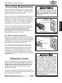
Jfd\[ljkZi\Xk\[Ypgfn\ijXe[`e^#jXn`e^#^i`e[`e^#[i`cc`e^#Xe[
fk_\iZfejkilZk`feXZk`m`k`\jZfekX`ejZ_\d`ZXcjbefnekfk_\JkXk\f]
:Xc`]fie`XkfZXlj\ZXeZ\i#Y`ik_[\]\Zkjfifk_\ii\gif[lZk`m\_Xid%
Jfd\\oXdgc\jf]k_\j\Z_\d`ZXcjXi\1
C\X[]ifdc\X[$YXj\[gX`ekj%
:ipjkXcc`e\j`c`ZX]ifdYi`Zbj#Z\d\ekXe[fk_\idXjfeipgif[lZkj%
8ij\e`ZXe[Z_ifd`ld]ifdZ_\d`ZXccp$ki\Xk\[cldY\i%
Pflii`jb]ifdk_\j\\ogfjli\jmXi`\j#[\g\e[`e^fe_fnf]k\epfl
[fk_`jkpg\f]nfib%Kfi\[lZ\pfli\ogfjli\kfk_\j\Z_\d`ZXcj1
Nfib`eXn\ccm\ek`cXk\[Xi\X#Xe[nfibn`k_Xggifm\[jX]\kp\hl`g$
d\ek#jlZ_Xjk_fj\[ljkdXjbjk_XkXi\jg\Z`Xccp[\j`^e\[kf]`ck\i
flkd`ZifjZfg`ZgXik`Zc\j%
SAFETY ...............................................6
Standard Machinery Safety Instructions ...... 6
Additional Safety for Table Saws .............. 8
Kickback ........................................... 9
PARTS ............................................... 74
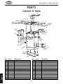
Cabinet & Table ................................ 74
Trunnion & Switch Breakdown ............... 75
Trunnion & Switch Parts List ................. 76
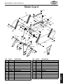
Blade Guard ..................................... 77
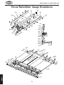
Fence/Rails/Miter Gauge Breakdown ....... 78
Fence/Rails/Miter Gauge Parts List ......... 79
Label Placement ............................... 80
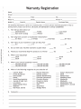
WARRANTY ........................................ 85
G8IKJ
LJ<K?<HL@:B>L@;<G8><C89<CJKFJ<8I:?FLK@E=FID8K@FE=8JK
J<IM@:<
For Your Own Safety Read Owner's Manual
Before Operating Saw
a) Wear eye protection.
b) Use saw-blade guard and riving knife
for every operation for which it can be
used, including all through sawing.
c) Keep hands out of the line of saw blade.
d) Use a push-stick when required.
e) Pay particular attention to instructions
on reducing risk of kickback.
f) Do not perform any operation freehand.
g) Never reach around or over saw blade.
D8@EK<E8E:<
SHOP-MADE SAFETY ACCESSORIES ............ 44
Featherboards .................................. 44
Push Sticks ...................................... 47
Push Blocks ...................................... 48
SERVICE ............................................ 56
General .......................................... 56
Belt Service ..................................... 56
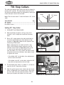
Tilt Stop Collars ................................ 58
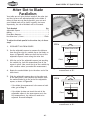
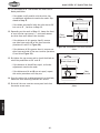
Miter Slot to Blade Parallelism............... 60
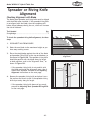
Spreader or Riving Knife Alignment ......... 63
Fence Adjustments ............................. 65
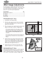
Miter Gauge Adjustments ..................... 68
Electrical Safety Instructions................. 69
Wiring Diagram ................................. 70
Electrical Components ........................ 71
Troubleshooting................................. 72
FG<I8K@FEJ
OPERATIONS ....................................... 22
General .......................................... 22
Basic Controls ................................... 22
Operation Overview ........................... 23
Workpiece Inspection .......................... 23
Non-Through & Through Cuts ................ 24
Blade Size Requirements ...................... 25
Blade Selection ................................. 25
Blade Installation .............................. 27
Blade Guard Assembly ......................... 28
Riving Knife ..................................... 31
Ripping ........................................... 32
Crosscutting ..................................... 33
Miter Cuts ....................................... 34
Blade Tilt Cuts .................................. 34
Dado Cutting .................................... 35
Rabbet Cutting ................................. 38
Resawing ......................................... 40
MAINTENANCE .................................... 54
Schedule ......................................... 54
Cleaning ......................................... 54
Lubrication ...................................... 55
J<KLG
SETUP............................................... 13
Unpacking ....................................... 13
Needed for Setup .............................. 13
Inventory ........................................ 14
Machine Placement ............................ 15
Cleaning Machine............................... 15
Assembly ......................................... 16
Dust Collection ................................. 20
Test Run.......................................... 21
Recommended Adjustments .................. 21
ACCESSORIES ...................................... 52
Table Saw Accessories ......................... 52
<C<:KI@:8C
ELECTRICAL ....................................... 10
Circuit Requirements .......................... 10
Grounding Requirements ...................... 11
Extension Cords ................................ 11
Voltage Conversion ............................. 12
Narrow-Rip Auxiliary Fence & Push Block .. 49
Outfeed & Support Tables .................... 51
Crosscut Sled.................................... 51
J8=<KP
INTRODUCTION .....................................2
Woodstock Technical Support .................. 2
Controls and Features ........................... 2
Machine Specifications .......................... 3
@EKIF;L:K@FE
:fek\ekj
@EKIF;L:K@FE
Df[\cN(/)+('?pYi`[KXYc\JXn
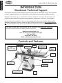
INTRODUCTION
Woodstock Technical Support
This machine has been specially designed to provide many years of trouble-free service. Close attention
to detail, ruggedly built parts and a rigid quality control program assure safe and reliable operation.
Woodstock International, Inc. is committed to customer satisfaction. Our intent with this manual is to
include the basic information for safety, setup, operation, maintenance, and service of this product.
We stand behind our machines! In the event that questions arise about your machine, please contact
Woodstock International Technical Support at (360) 734-3482 or send e-mail to: k\Z_$jlggfik7j_fg]fo%
Y`q. Our knowledgeable staff will help you troubleshoot problems and process warranty claims.
If you need the latest edition of this manual, you can download it from _kkg1&&nnn%j_fg]fo%Y`q.
If you have comments about this manual, please contact us at:
Nff[jkfZb@ek\ieXk`feXc#@eZ%
8kke1K\Z_e`ZXc;fZld\ekXk`feDXeX^\i
G%F%9fo)*'0
9\cc`e^_Xd#N80/)).
<dX`c1dXelXcj7nff[jkfZb`ek%Zfd
Controls and Features
Miter Gauge
Fence
Blade Guard
Left
Extension Wing
Right
Extension Wing
Extension
Table
Fence
Rail Tube
Blade Tilt
Handwheel & Lock
START/STOP
Switch
4" Dust Port
Blade Height
Handwheel & Lock
Tilt
Scale
Figure 1. Model W1824 identification.
-2-
@EKIF;L:K@FE
Df[\cN(/)+('?pYi`[KXYc\JXn
02'(/:
+<%5,'7$%/(6$::,7+(;7(16,217$%/(
##$$%'
*$+$ *
; <;=<;
$+$ <;
>
?@ J?<;
?<;
Q<X
# J<*Y
Z'@[$ +$$$ >;$\]$^
\$ _'[$$@
`@'@\]@$ <
X^{=$$| <}Q@@~
X'$\\| <<<<<}
@@@@~
X'$\{$| <<<J}J@@~
`@'@] =J
\ _<>Q
?$[$Y Q=
?$[$ Q<X
?$[$\$ $@_'[$
`@'@]#'?<]$ >=
`@'@]#'?Q]$ >=J
`@'@XX\>$ <
`@'@X_\ $[* [Y QQ
[Y]
[Y| >=
]$[#$\ J
]$[\?`@'@#' >=
-3-
@EKIF;L:K@FE
Df[\cN(/)+('?pYi`[KXYc\JXn
#@|>+=*]
Y_ >=
Y >=
Y* >=
X '$'[
X_ Q>Q=
X X* >Q=
$' >
$'Y =
$'Y* =
[ $>$'#%$
#%$
#@+=_+$'$
#[ $>$@
$' #%$
?@[ +*]
X $' ?'@'@
'$ #$
+$#
Z'@[$]'$ ]'$Y [\ ]<Q?
!
<[
}>>~`]}$>>[|~`* Q
`J`<
$}_`~ <`>=
!
"#
#$[$=|
# J
[
_``* <`J`
"$
#$[$
# [
_``* ``
"%
#$[$
# X
[
_``* J`Q`
-4-
&
+$X'$@ <;=<;J<*Y
$+$; <;
'>_#'$$X J?<;
?<;
@'@#$'Y <?<;<?<;
+; <;
#$_ J
#$' '
'%'
%'' Z?J><$<;
X@@'=' Z?Q><$<;
%$ %<<
#'$$ #
$$ $
$Z'@[$_ %]_[#[
?@[@ ?$`@*'$
$>$'$[
#$$'
'$
>@$'
#@|>+*]
@
+$
'|>$$^|['$@[
{'$|[$'
%'$'$[[$
]^['$+[=[>||[|+
-5-
@EKIF;L:K@FE
Df[\cN(/)+('?pYi`[KXYc\JXn
Df[\cN(/)+('?pYi`[KXYc\JXn
J8=<KP
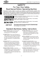
SAFETY
J8=<KP
For Your Own Safety,
Read Manual Before Operating Machine
K_\ gligfj\ f] jX]\kp jpdYfcj `j kf XkkiXZk pfli Xkk\ek`fe kf gfjj`Yc\ _XqXi[flj Zfe[`k`fej% K_`j
dXelXclj\jXj\i`\jf]jpdYfcjXe[j`^eXcnfi[j`ek\e[\[kfZfem\pk_\c\m\cf]`dgfikXeZ\f]k_\
jX]\kpd\jjX^\j%K_\gif^i\jj`fef]jpdYfcj`j[\jZi`Y\[Y\cfn%I\d\dY\ik_XkjX]\kpd\jjX^\jYp
k_\dj\cm\j [f efk \c`d`eXk\ [Xe^\i Xe[ Xi\ efk X jlYjk`klk\ ]fi gifg\i XZZ`[\ek gi\m\ek`fe d\X$
jli\jÇk_`ji\jgfej`Y`c`kp`jlck`dXk\cplgkfk_\fg\iXkfi
@e[`ZXk\jXe`dd`e\ekcp_XqXi[fljj`klXk`fen_`Z_#`]efkXmf`[\[#
N@CCi\jlck`e[\Xk_fij\i`flj`ealip%
@e[`ZXk\jXgfk\ek`Xccp_XqXi[fljj`klXk`fen_`Z_#`]efkXmf`[\[#
:FLC;i\jlck`e[\Xk_fij\i`flj`ealip%
@e[`ZXk\jXgfk\ek`Xccp_XqXi[fljj`klXk`fen_`Z_#`]efkXmf`[\[#
D8Pi\jlck`ed`efifidf[\iXk\`ealip%
EFK@:<
K_`jjpdYfc`jlj\[kfXc\ikk_\lj\ikflj\]lc`e]fidXk`feXYflk
gifg\ifg\iXk`fef]k_\\hl`gd\ek#Xe[&fiXj`klXk`fek_XkdXp
ZXlj\[XdX^\kfk_\dXZ_`e\ip%
Standard
Machinery Safety Instructions
JkXe[Xi[DXZ_`e\ipJX]\kp@ejkilZk`fej
FNE<IËJD8EL8C% Read and understand this
owner’s manual BEFORE using machine.
Untrained users can be seriously hurt.
?<8I@E>GIFK<:K@FE% Always wear hearing
protection when operating or observing
loud machinery. Extended exposure to this
noise without hearing protection can cause
permanent hearing loss.
<P<GIFK<:K@FE% Always wear ANSI-approved
safety glasses or a face shield when operating
or observing machinery to reduce the risk of
eye injury or blindness from flying particles.
Everyday eyeglasses are not approved safety
glasses.
D<EK8C8C<IKE<JJ% Be mentally alert when
running machinery. Never operate under the
influence of drugs or alcohol, when tired, or
when distracted.
?8Q8I;FLJ;LJK% Dust created while using
machinery may cause cancer, birth defects,
or long-term respiratory damage. Be aware
of dust hazards associated with workpiece
materials, and always wear a NIOSH-approved
respirator to reduce your risk.
;@J:FEE<:K@E>GFN<IJLGGCP% Always
disconnect machine from power supply before
servicing, adjusting, or changing cutting tools
(bits, blades, cutters, etc.). Make sure switch
is in OFF position before reconnecting to avoid
an unexpected or unintentional start.
N<8I@E>GIFG<I8GG8I<C% Do not wear
clothing, apparel, or jewelry that can become
entangled in moving parts. Always tie back
or cover long hair. Wear non-slip footwear to
avoid accidental slips which could cause a loss
of workpiece control.
;8E><IFLJ<EM@IFED<EKJ% Do not use
machinery in wet or rainy locations, cluttered
areas, around flammables, or in poorly-lit
areas. Keep work area clean, dry, and welllighted to minimize risk of injury.
-6-
Df[\cN(/)+('?pYi`[KXYc\JXn
JK89C<D8:?@E<% Unexpected movement during
operations greatly increases the risk of injury
and loss of control. Verify machines are
stable/secure and mobile bases (if used) are
locked before starting.
=FI:@E>D8:?@E<IP% Do not force machine. It
will do the job safer and better at the rate for
which it was designed.
FECPLJ<8J@EK<E;<;% Only use machine for
its intended purpose. Never modify or alter
machine for a purpose not intended by the
manufacturer or serious injury may result!
8NBN8I;GFJ@K@FEJ% Keep proper footing and
balance at all times when operating machine.
Do not overreach! Avoid awkward hand
positions that make workpiece control difficult
or increase the risk of accidental injury.
LJ<I<:FDD<E;<;8::<JJFI@<J% Consult
this owner’s manual or the manufacturer for
recommended accessories. Using improper
accessories will increase the risk of serious
injury.
LE8KK<E;<;FG<I8K@FE% Never leave machine
running while unattended. Turn machine off
and ensure all moving parts completely stop
before walking away.
:?@C;I<E9PJK8E;<IJ% Keep children and
bystanders a safe distance away from work
area. Stop using machine if children or
bystanders become a distraction.
D8@EK8@EN@K?:8I<% Follow all maintenance
instructions and lubrication schedules to
keep machine in good working condition. An
improperly maintained machine may increase
the risk of serious injury.
I<DFM<8;ALJK@E>KFFCJ% Never leave
adjustment tools, chuck keys, wrenches, etc.
in or on machine—especially near moving
parts. Verify removal before starting!
:?<:B;8D8><;G8IKJ% Regularly inspect
machine for damaged parts, loose bolts,
mis-adjusted or mis-aligned parts, binding,
or any other conditions that may affect safe
operation. Always repair or replace damaged
parts, wires, cords, or plugs before operating
machine.
J<:LI@E>NFIBG@<:<% When required, use
clamps or vises to secure workpiece. A secured
workpiece protects hands and frees both of
them to operate the machine.
=<<;;@I<:K@FE% Unless otherwise noted, feed
work against the rotation of blades or cutters.
Feeding in the same direction of rotation may
pull your hand into the cut.
D8@EK8@EGFN<I:FI;J%When disconnecting
cord-connected machines from power, grab
and pull the plug—NOT the cord. Pulling the
cord may damage the wires inside. Do not
handle the cord/plug with wet hands. Avoid
cord damage by keeping it away from heated
surfaces, high traffic areas, harsh chemicals,
and wet or damp locations.
>L8I;J:FM<IJ% Guards and covers can
protect you from accidental contact with
moving parts or flying debris. Make sure
they are properly installed, undamaged, and
working correctly before using machine.
<OG<I@<E:@E>;@==@:LCK@<J% If at any time you
are experiencing difficulties performing the
intended operation, stop using the machine!
Contact our Technical Support for help at
(360) 734-3482.
E<M<IJK8E;FED8:?@E<% Serious injury or
accidental contact with cutting tool may
occur if machine is tipped. Machine may be
damaged.
-7-
J8=<KP
8GGIFM<;FG<I8K@FE% Untrained operators
can be seriously hurt by machinery. Only
allow trained or properly supervised people
to use machine. When machine is not being
used, disconnect power, remove switch keys,
or lock-out machine to prevent unauthorized
use—especially around children. Make
workshop kid proof!
Df[\cN(/)+('?pYi`[KXYc\JXn
J8=<KP
Additional Safety for Table Saws
HAND POSITIONING. Touching a spinning
saw blade will cause serious laceration or
amputation injuries. Never purposely touch
a saw blade during operation. Always keep
hands/fingers out of the blade path; place
them where they cannot slip into the blade
accidentally. Never reach around, behind, or
over the blade.
FEEDING WORKPIECE. Feeding the workpiece
incorrectly will increase risk of kickback. Never
start the saw with a workpiece touching the
blade; allow the blade to reach full speed
before cutting. Only feed the workpiece against
the direction of blade rotation. Always use
some type of guide (fence, miter gauge, sliding
table or sled, etc.) to feed the workpiece in
a straight line. Never back a workpiece out of
a cut or try to move it backwards or sideways
after starting a cut. Feed cuts all the way
through to completion. Never perform any
operation “freehand” (making a cut without
using a fence, miter gauge, or other guide).
BLADE GUARD. Operating the saw with the
blade guard removed greatly increases the risk
of severe laceration or amputation injuries
from accidental blade contact. Use the
blade guard for all “through cuts”. A through
cut is an operation where the blade cuts
completely through the top of the workpiece.
Make sure the blade guard is installed and
adjusted correctly; promptly repair or replace
it if damaged. Always re-install blade guard
immediately after operations that require its
removal.
PUSH STICKS/BLOCKS. Use push sticks or push
blocks whenever possible to keep your hands
farther away from the blade while cutting. In
the event of an accident, these devices will
often take damage that would have happened
to hands/fingers.
RIVING KNIFE. The riving knife keeps the kerf
open behind the blade, which reduces the
risk of kickback. Use the riving knife for all
“non-through cuts”. A non-through cut is
an operation where the blade does not cut
through the top of the workpiece. Make sure
the riving knife is aligned and positioned
correctly; and promptly repair or replace it
if damaged. Using the riving knife incorrectly
will increase the risk of kickback or accidental
blade contact.
CUT-OFF PIECES. Never use your hands to move
cut-offs away from the blade while the saw is
running. If a cut-off becomes trapped between
the blade and table insert, turn the saw OFF
and allow the blade to completely stop before
removing it.
BLADE ADJUSTMENTS. Adjusting the blade
height or tilt during operation increases the
risk of crashing the blade and sending metal
fragments flying with deadly force at the
operator or bystanders. Only adjust the blade
height and tilt when the saw is turned OFF and
the blade is completely stopped.
KICKBACK. Kickback occurs when the saw
blade ejects the workpiece back toward the
operator. Know how to reduce the risk of
kickback, and learn how to protect yourself if
it does occur.
DAMAGED SAW BLADES. Never use blades that
have been dropped or otherwise damaged.
Damaged blades can fly apart and strike the
operator with shards of metal.
FENCE. Using or adjusting the fence incorrectly
will increase risk of kickback. Make sure the
fence remains properly adjusted and parallel
with the blade. Always lock the fence in place
before operation.
DADO AND RABBET OPERATIONS. DO NOT
attempt dado or rabbeting operations without
first reading those sections in this manual.
Dado and rabbeting operations require special
attention because they must be performed
with the blade guard removed.
-8-
Df[\cN(/)+('?pYi`[KXYc\JXn
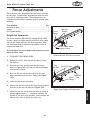
Kickback
The splitter or riving knife maintains the kerf
in the workpiece, reducing the chance of
kickback. Always use the riving knife for all
non-through operations, unless a dado blade
is installed. Always use the splitter with the
blade guard for all through cuts.
•
Feed cuts through to completion. Anytime
you stop feeding a workpiece in the middle
of a cut, the chance of kickback is greatly
increased.
•
Keep the blade guard installed and in
good working order. Only remove it when
performing non-through cuts and immediately
re-install the blade guard when finished.
Remember, always use the riving knife for all
non-through operations, unless a dado blade
is installed.
•
Make multiple, shallow passes when
performing a non-through cut. Making a deep
non-through cut will greatly increase the
chance of kickback.
Kickback is a high speed expulsion of the
workpiece from the saw blade, which occurs when
the saw blade grabs the workpiece instead of cuts
it.
The danger of kickback is that it happens faster
than the operator can react, so if the operator’s
hands are in a bad position, they could get pulled
into the blade. Also, kickback can cause serious
impact injuries if the operator is struck by the
ejected workpiece.
The lack of warning and high risk of injury from
kickback makes it extremely important to: (1)
avoid doing anything that will increase the risk
of occurrence, and (2) work carefully to protect
yourself in case it does occur.
Avoiding Kickback
•
•
•
•
DO NOT cut a workpiece that is excessively
warped or twisted. The workpiece must be
able to slide across the table and fence in a
stable manner without any rocking, rotating,
or shifting—if any of these movements occur
during the cut, kickback will likely occur.
Workpieces that have minor warping must
be cut with the cupped-side down against
the table; the edge of the workpiece that is
placed against the fence must be straight or
straightened with a jointer.
Protecting Yourself from Kickback
Never attempt freehand cuts. Always use
the rip fence or miter gauge to support
the workpiece. If the workpiece is not fed
parallel with the blade, kickback will likely
occur.
Make sure the splitter or riving knife is
aligned with the blade. A misaligned splitter
or riving knife can cause the workpiece
to catch or bind, increasing the chance of
kickback. If you think that your splitter or
riving knife is not aligned with the blade,
check it immediately!
Ensure that the rip fence locks parallel with
the blade; otherwise, the chances of kickback
are extreme.
-9-
•
Stand to the side of the blade during every
cut. If kickback does occur, the thrown
workpiece usually travels directly in front of
the blade.
•
Wear safety glasses or a face shield. In the
event of kickback, your eyes and face are the
most vulnerable part of your body.
•
Never, for any reason, place your hand behind
the blade. Should kickback occur, your hand
will be pulled into the blade.
•
Use a push stick to keep your hands farther
away from the moving blade. If kickback
occurs, the push stick will most likely take
the damage that your hand would have
received.
•
Use featherboards or anti-kickback devices to
prevent or slow down kickback.
<C<:KI@:8C
•
Df[\cN(/)+('?pYi`[KXYc\JXn
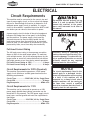
ELECTRICAL
Circuit Requirements
<C<:KI@:8C
This machine must be connected to the correct size and
type of power supply circuit, or fire or electrical damage
may occur. Read through this section to determine if an
adequate power supply circuit is available. If a correct
circuit is not available, a qualified electrician MUST install
one before you can connect the machine to power.
K_\ dXZ_`e\ dljk Y\ gifg\icp j\k lg
Y\]fi\ `k `j jX]\ kf fg\iXk\% ;F EFK
Zfee\Zk k_`j dXZ_`e\ kf k_\ gfn\i
jfliZ\ lek`c `ejkilZk\[ kf [f cXk\i `e
k_`jdXelXc%
A power supply circuit includes all electrical equipment
between the breaker box or fuse panel in the building
and the machine. The power supply circuit used for
this machine must be sized to safely handle the fullload current drawn from the machine for an extended
period of time. (If this machine is connected to a circuit
protected by fuses, use a time delay fuse marked D.)
Full-Load Current Rating
The full-load current rating is the amperage a machine
draws at 100% of the rated output power. On machines
with multiple motors, this is the amperage drawn by the
largest motor or sum of all motors and electrical devices
that might operate at one time during normal operations.
Full-Load Current Rating at 220V ....................8 Amps
Full-Load Current Rating at 110V .................. 16 Amps
Circuit Requirements for 220V (Prewired)
This machine is prewired to operate on a 220V power
supply circuit that has a verified ground and meets the
following requirements:
Circuit Type ...............220V/240V, 60 Hz, Single-Phase
Circuit Size ............................................. 20 Amps
Plug/Receptacle .................................... NEMA 6-20
Circuit Requirements for 110V
This machine can be converted to operate on a 110V
power supply (details about voltage conversion can be
found later in this manual). The 110V power supply circuit
must have a verified ground and meet the requirements
that follow:
Circuit Type ............... 110V/120V, 60 Hz, Single-Phase
Circuit Size ............................................. 20 Amps
Plug/Receptacle .................................... NEMA 5-20
-10-
@eZfii\Zkcp n`i`e^ fi ^ifle[`e^ k_`j
dXZ_`e\ZXeZXlj\\c\ZkifZlk`fe#]`i\#
fidXZ_`e\[XdX^\%Kfi\[lZ\k_`ji`jb#
fecp X hlXc`]`\[ \c\Zki`Z`Xe fi j\im`Z\
g\ijfee\c j_flc[ [f Xep i\hl`i\[
\c\Zki`ZXcnfib]fik_`jdXZ_`e\%
EFK@:<
K_\ Z`iZl`k i\hl`i\d\ekj c`jk\[ `e k_`j
dXelXc Xggcp kf X [\[`ZXk\[ Z`iZl`kÇ
n_\i\fecpfe\dXZ_`e\n`ccY\ilee`e^
Xk X k`d\% @] k_`j dXZ_`e\ n`cc Y\
Zfee\Zk\[ kf X j_Xi\[ Z`iZl`k n_\i\
dlck`gc\ dXZ_`e\j n`cc Y\ ilee`e^ Xk
k_\ jXd\ k`d\# Zfejlck X hlXc`]`\[
\c\Zki`Z`Xekf\ejli\k_Xkk_\Z`iZl`k`j
gifg\icpj`q\[]fijX]\fg\iXk`fe%
Df[\cN(/)+('?pYi`[KXYc\JXn
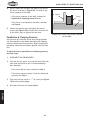
Grounding Requirements
This machine MUST be grounded. In the event of certain
types of malfunctions or breakdowns, grounding provides
a path of least resistance for electric current to travel—in
order to reduce the risk of electric shock.
Check with a qualified electrician or service personnel
if you do not understand these grounding requirements,
or if you are in doubt about whether the tool is
properly grounded. If you ever notice that a cord or
plug is damaged or worn, disconnect it from power, and
immediately replace it with a new one.
GROUNDED
6-20 RECEPTACLE
Current Carrying Prongs
6-20 PLUG
Grounding Prong
Figure 2. NEMA 6-20 plug & receptacle.
For 220V Connection (Prewired)
This machine is equipped with a power cord that has an
equipment-grounding wire and NEMA 6-20 grounding plug.
The plug must only be inserted into a matching receptacle
(see Figure) that is properly installed and grounded in
accordance with local codes and ordinances.
GROUNDED
5-20 RECEPTACLE
Hot
Neutral
5-20 PLUG
For 110V Connection (Must be Rewired)
A NEMA 5-20 plug has a grounding prong that must be
attached to the equipment-grounding wire inside the
included power cord. The plug must only be inserted
into a matching receptacle (see Figure) that is properly
installed and grounded in accordance with all local codes
and ordinances.
Extension Cords
We do not recommend using an extension cord with this
machine. Extension cords cause voltage drop, which may
damage electrical components and shorten motor life.
Voltage drop increases with longer extension cords and
the gauge smaller gauge sizes (higher gauge numbers
indicate smaller sizes).
Any extension cord used with this machine must contain a
ground wire, match the required plug and receptacle, and
meet the following requirements:
Minimum Gauge Size at 220V ...................... 12 AWG
Maximum Length (Shorter is Better).................50 ft.
-11-
Grounding Prong
Figure 3. NEMA 5-20 plug & receptacle.
;F EFK df[`]p k_\ gifm`[\[ gcl^ fi
lj\ Xe X[Xgk\i `] k_\ gcl^ n`cc efk ]`k
pfli i\Z\gkXZc\% K_`j `j Xe `e[`ZXk`fe
k_Xk pfli gfn\i jlggcp Z`iZl`k [f\j
EFK d\\k k_\ i\hl`i\d\ekj ]fi k_\
dXZ_`e\2 _Xm\ Xe \c\Zki`Z`Xe `ejkXcc
k_\ Zfii\Zk gfn\i jlggcp Z`iZl`k% @]
k_\ dXZ_`e\ dljk Y\ i\Zfee\Zk\[ ]fi
lj\ fe X [`]]\i\ek kpg\ f] \c\Zki`Z
Z`iZl`k# k_\ i\Zfee\Zk`fe j_flc[ Y\
dX[\ Yp X hlXc`]`\[ \c\Zki`Z`Xe fi
j\im`Z\ g\ijfee\c2 X]k\i i\Zfee\Zk`fe#
k_\dXZ_`e\dljkZfdgcpn`k_XcccfZXc
Zf[\jXe[fi[`eXeZ\j%
<C<:KI@:8C
Improper connection of the equipment-grounding wire will
increase the risk of electric shock. The wire with green
insulation (with/without yellow stripes) is the equipmentgrounding wire. If repair or replacement of the power
cord or plug is necessary, do not connect the equipmentgrounding wire to a live (current carrying) terminal.
K_\ dXZ_`e\ dljk Y\ gifg\icp j\k lg
Y\]fi\ `k `j jX]\ kf fg\iXk\% ;F EFK
Zfee\Zk k_`j dXZ_`e\ kf k_\ gfn\i
jfliZ\ lek`c `ejkilZk\[ kf [f cXk\i `e
k_`jdXelXc%
200MFD
(As Recommended)
60MFD
Ground
250VAC
300VAC
Neutral
Model W1824 10" Hybrid Table Saw
Hot
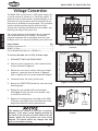
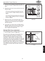
Voltage Conversion
ELECTRICAL
The Model 1824 is prewired for a 220V power supply, but
Motor Rewired
it can be rewired to operate
on a 110V power supply. To
for 110V
reduce the risk of electrocution, machine damage, or an
electrical fire, this procedure must be performed by an
electrician or qualified service personnel. The procedure
involves moving terminal jumpers inside the motor
junction box, replacing the machine circuit breaker, and
replacing the plug on the power cord.
The require machine circuit breaker can be purchased
from an authorized Shop Fox dealer. The required
<gdjcY
plug and receptacle can be purchased from your local
hardware store or it may be provided by your electrician.
110V/220V
Hot
MOTOR
Hot
Motor Prewired
for 220V
Ground
Rewired for 110V
Loosen
These
Screws
Center Jumpers
<gdjcY
Items Needed
Qty
Figure 4. Locations of screws to be
Phillips Screwdriver #2..........................................1
loosened.
NEMA 5-20 Plug...................................................1
Rewired for 110V
Circuit Breaker 20A (Part No. X1824204-1)..................1
To convert the table saw to 110V, do these steps:
Motor Rewired
for 110V
Motor Prewi
for 220V
1. DISCONNECT TABLE SAW FROM POWER!
2. Open the motor junction box, then loosen the four
screws indicated in Figure 4.
3. Remove the two center jumpers (they are stacked
together), reposition them as shown in Figure 5,
then re-tighten the four screws loosened in Step 2.
<gdjcY
New Jumper Locations
4. Close and secure the motor junction box.
5. Remove the START/STOP switch box from the switch
mounting plate.
Figure 5. Relocated jumpers.
Rewired for 110V
6. Replace the pre-installed 10A circuit breaker
(see Figure 6) with the 20A circuit breaker, then
re-install the switch box.
7. Replace the existing power cord plug with a NEMA
5-20 plug, according to the instructions and wiring
diagram provided by the plug manufacturer.
This manual was current at the time of printing.
However, if the motor wiring diagram provided on
the inside of the junction box cover differs from this
manual, always use the junction box cover wiring
diagram. This should reflect any changes that may
have occurred after printing.
-12-
Circuit
Breaker
Figure 6. Location of switch circuit
breaker.
Df[\cN(/)+('?pYi`[KXYc\JXn
SETUP
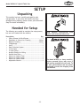
Unpacking
This machine has been carefully packaged for safe
transportation. If you notice the machine has been
damaged during shipping, please contact your authorized
Shop Fox dealer immediately.
Needed for Setup
The following are needed to complete the setup process,
but are not included with the machine:
-13-
J<KLG
Description
Qty
• Safety Glasses for Each Person ..........................1
• Degreaser or Solvent for Cleaning ................Varies
• Rags for Cleaning ....................................Varies
• Straightedge ................................................1
• Level .........................................................1
• Dust Collection System ...................................1
• 4" Dust Hose ................................................1
• 4" Hose Clamp..............................................1
• Another Person for Lifting ...............................1
• Needle Nose Pliers ........................................1
• Wrench or Socket 17mm .................................1
• Wrench or Socket 14mm .................................1
• Wrench or Socket 10mm .................................1
• Adjustable Wrench ........................................1
B\\g dXZ_`e\ [`jZfee\Zk\[ ]ifd
gfn\ilek`c`ejkilZk\[fk_\in`j\%
The Model W1824 is a heavy machine.
Serious personal injury may occur if
safe moving methods are not used. To
be safe, get assistance and use power
equipment to move the shipping crate
and machine.
Df[\cN(/)+('?pYi`[KXYc\JXn
Inventory
The following is a description of the main components
shipped with the Model W1824. Lay the components out
to inventory them.
J<KLG
Efk\1 If you can't find an item on this list, check the
mounting location on the machine or examine the
packaging materials carefully. Occasionally we pre-install
certain components for safer shipping.
A
Shipping Inventory: (Figures 7–10)
Qty
A. Cabinet Assembly ..........................................1
B. Extension Wings............................................2
C. Saw Blade 10" x 40T.......................................1
D. Wrench 7⁄16" x 13mm ....................................1
E. Arbor Wrench 24mm ......................................1
F. Access Door .................................................1
G. Blade Guard Assembly & Riving Knife ........... 1 Each
H. Push Stick ...................................................1
I. Handwheel Handles .......................................2
J. Miter Gauge ................................................1
K. Hex Wrench 6-Piece Set 2.5-8mm ......................1
L. Dado Table Insert ..........................................1
M. Fence Rail Tube 58" w/Scale ............................1
N. Rear Rail 53" (6-Holes) ....................................1
O. Front Rail 53" (6-Holes)...................................1
P. Fence Assembly ............................................1
Q. Extension Table ............................................1
Hardware (Not Shown)
Qty
• Cap Screws M5-.8 x 12 (Mag Switch) ...................2
• Lock Washers 5mm (Mag Switch) .......................2
• Flat Washers 5mm (Mag Switch) ........................2
• Flat Head Screws M8-1.25 x 35 (Front Rail/Tables)..6
• Flat Washers 8mm (Front Rail/Tables) .................8
• Lock Washers 8mm (Front Rail/Tables) ................6
• Hex Nuts M8-1.25 (Front Rail/Tables) ..................6
• Cap Screws M6-1 x 16 (Front Rail/Tube)...............5
• Flat Washers 6mm (Front Rail/Tube) ...................5
• Lock Washers (Front Rail/Tube) .........................5
• Hex Bolts M10-1.5 x 25 (Rear Rail/Table) .............2
• Flat Washers 10mm (Rear Rail/Table) ..................2
• Lock Washers 10mm (Rear Rail/Table) .................2
• Hex Bolts M8-1.25 x 35 (Rear Rail/Wing/Ext Table) .4
• Hex Nuts M8-1.25 (Rear Rail/Wing/Ext Table) ........4
• Flat Washers 8mm (Rear Rail/Wing/Ext Table) .......8
• Lock Washers 8mm (Rear Rail/Wing/Ext Table) ......4
Figure 7. Cabinet assembly.
B
Figure 8. Extension wings.
F
C
E
D
G
J
L
H
I
K
Figure 9. Small components.
M
N
O
P
Q
Figure 10. Fence components.
-14-
Df[\cN(/)+('?pYi`[KXYc\JXn
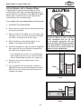
Machine Placement
=cffiCfX[1 This machine distributes a
heavy load in a small footprint. Some
residential floors may require additional
bracing to support both machine and
operator.
Nfib`e^:c\XiXeZ\j1 Consider existing and
anticipated needs, size of material to be
processed through the machine, and space
for auxiliary stands, work tables or other
machinery when establishing a location for
your table saw.
C`^_k`e^1 Lighting should be bright enough
to eliminate shadow and prevent eye strain.
<c\Zki`ZXc1Electrical circuits must be
dedicated or large enough to handle
amperage requirements. Outlets must be
located near each machine, so power or
extension cords are clear of high-traffic
areas. Follow local electrical codes for
proper installation of new lighting, outlets,
or circuits.
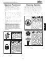
The table and other unpainted parts of your
table saw are coated with a waxy grease that
protects them from corrosion during shipment.
Clean this grease off with a solvent cleaner or
citrus-based degreaser. DO NOT use chlorinebased solvents such as brake parts cleaner or
acetone—if you happen to splash some onto a
painted surface, you will ruin the finish.
E<M<IZc\Xen`k_^Xjfc`e\
fi fk_\i g\kifc\ld$
YXj\[jfcm\ekj%Dfjk_Xm\
cfn ]cXj_ gf`ekj# n_`Z_
dXb\ k_\d \oki\d\cp
]cXddXYc\% 8 i`jb f]
\ogcfj`fe Xe[ Ylie`e^
\o`jkj `] k_\j\ gif[lZkj
Xi\lj\[%J\i`fljg\ijfeXc
`ealip dXp fZZli `] k_`j
nXie`e^`j`^efi\[
8CN8PJ nfib `e n\cc$
m\ek`cXk\[Xi\Xj]Xi]ifd
gfjj`Yc\ `^e`k`fe jfliZ\j
n_\e lj`e^ jfcm\ekj kf
Zc\Xe dXZ_`e\ip% DXep
jfcm\ekj Xi\ kfo`Z n_\e
`e_Xc\[ fi `e^\jk\[% Lj\
ZXi\ n_\e [`jgfj`e^
f] nXjk\ iX^j Xe[
kfn\cj kf Y\ jli\ k_\p
;F EFK Zi\Xk\ ]`i\ fi
\em`ifed\ekXc_XqXi[j%
LJ< _\cg\ij fi gfn\i
c`]k`e^ \hl`gd\ek kf c`]k
k_`j dXZ_`e\% Fk_\in`j\#
j\i`flj g\ijfeXc `ealip
dXpfZZli%
D8B< pfli j_fg ÈZ_`c[
jX]\%É <ejli\ k_Xk pfli
nfibgcXZ\ `j `eXZZ\jj`Yc\
kf Z_`c[i\e Yp Zcfj`e^ Xe[
cfZb`e^Xcc\ekiXeZ\jn_\e
pflXi\XnXp%E<M<IXccfn
lekiX`e\[ m`j`kfij `e pfli
j_fg n_\e Xjj\dYc`e^#
X[aljk`e^ fi fg\iXk`e^
\hl`gd\ek%
-15-
J<KLG
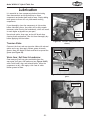
Cleaning Machine
Df[\cN(/)+('?pYi`[KXYc\JXn
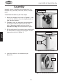
Assembly
Assembly consists of installing minor components, the
extension wings and table, fence rails, fence, and blade
guard.
Shipping Brace
To assemble the table saw, do these steps:
Remove the shipping brace shown in Figure 11, then
re-install the fasteners. Save the shipping brace for
later machine transport.
2.
Thoroughly clean the heavy-duty rust preventative
off the gears inside the cabinet and coat them
with an appropriate metal protectant (refer to
Lubrication on Page 55 for the location of gears).
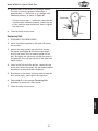
3.
Pull the switch out of the cabinet cavity, then attach
the access door by inserting the hinge pins into the
hinge sockets shown in Figure 12.
Figure 11. Location of the shipping brace.
Access Door
J<KLG
1.
Hinge
Sockets
Figure 12. Access door attached.
4.
Install the handles on the handwheels (see
Figure 13).
Handle
Figure 13. Handwheel handle installed.
-16-
Df[\cN(/)+('?pYi`[KXYc\JXn
5.
6.
Remove the (6) cap screws, flat washers, and lock
washers from both sides of the main table.
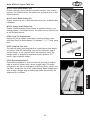
Extension Wings
Inspect the extension wings and main table mating
surfaces for burrs or foreign materials that may
inhibit assembly.
For a correct fit, the mating edges of the table and
wings must be clean, smooth, and flat. If necessary,
use a wire brush or file to remove any flashing,
dings, or high spots.
7.
While a helper holds the extension wings in place,
attach them to the main table with the (6) M10-1.5
x 25 cap screws, 10mm lock washers, and 10mm flat
washers removed in Step 5, as shown in Figure 14.
8.
Place a straightedge across the extension wings and
main table to make sure that the combined table
surface is flat.
x6
Figure 14. Extension wings attached.
J<KLG
— If the combined table surface is flat, skip to
Step 9.
— If the outside end of the extension wing tilts
down, place one or more strips of masking tape
along the bottom edge of the main table to shim
the end of the extension wing up (see Figure 15).
— If the outside end of the extension wing tilts up,
place one or more strips of masking tape along the
top edge of the main table to shim the end of the
extension wing down (see Figure 16).
Note: After reinstalling wings, remove all excess
masking tape with a razor blade.
Figure 15. Masking tape location for
shimming the wing up.
Figure 16. Masking tape location for
shimming the wing down.
-17-
Df[\cN(/)+('?pYi`[KXYc\JXn
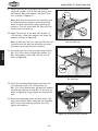
9.
Attach the front rail to the table and extension
wings with (4) M8-1.25 x 35 flat head screws, 8mm
flat washers, 8mm lock washers, and M8-1.25 hex
nuts, as shown in Figure 17.
:fjVa
Note: Make sure the top of the rail is parallel with
the table top surface along its entire length and
below the miter slots before fully tightening the
fasteners. This will ensure that the fence will ride
evenly across the table top.
x4
10. Attach the rear rail to the table with (2) M10-1.5
x 25 hex bolts, 10mm lock washers, and 10mm flat
washers, as shown in Figure 18.
J<KLG
Note: As with the front rail, make sure the rear rail
is parallel with the table top and below the miter
slots before fully tightening the fasteners.
Figure 17. Front rail attached parallel
with the table top.
11. Secure the rear rail to the extension wings with (2)
M8-1.25 x 35 hex bolts, (4) 8mm flat washers, (2)
8mm lock washers, and (2) M8-1.25 hex nuts, as
shown in Figure 18.
x2
x2
Figure 18. Rear rail attached parallel with
the table top.
12. Install the extension table between the front and
rear rails with (2) M8-1.25 x 35 hex bolts, (2)
M8-1.25 x 35 flat head screws, (8) 8mm flat washers,
(4) 8mm lock washers, and (4) M8-1.25 hex nuts, as
shown in Figure 19. Finger tighten the fasteners for
now.
13. Place the straightedge across the main table, right
wing, and extension table, make sure the extension
table is even with other top surfaces, then fully
tighten the fasteners.
x2
x2
x2
Figure 19. Extension table installed.
-18-
Df[\cN(/)+('?pYi`[KXYc\JXn
14. Attach the fence rail tube to the front rail with (5)
M6-1 x 16 cap screws, 6mm flat washers, and 6mm
lock washers, as shown in Figure 20. Finger tighten
the fasteners for now.
15. While standing in front of the fence rail tube, pull it
toward you as far as possible, then fully tighten the
fasteners installed in Step 14. This will help make
sure there is enough room for the fence to slide.
16. Install the blade as instructed in the Blade
Installation procedure on Page 27.
x5
17. Place the fence assembly onto the fence rail tube,
as shown in Figure 21.
Figure 20. Fence rail tube attached.
18. Perform the Miter Slot to Blade Parallelism
procedure as instructed on Page 60.
19. Perform the Fence Adjustments procedure as
instructed on Page 65.
J<KLG
If the table or fence is not properly aligned with the
blade, the workpiece could bind during a cutting
operation, which could result in kickback injuries.
The miter slot and fence MUST be correctly aligned
with the blade before continuing to Step 20.
Figure 21. Fence assembly installed.
20. Move the fence over so that it just touches the
blade, and verify that the indicator line is directly
over the zero line.
— If you need to correct the position of the indicator
line, loosen the screws on the pointer window,
adjust it so that the line is over the zero line on
the scale (see Figure 22), then re-tighten the
screws.
21. Install the blade guard as instructed in the Blade
Guard Assembly procedure on Page 28.
Cap Screws
Indicator
Line
Pointer Window
Figure 22. Fence pointer window
alignment.
-19-
Df[\cN(/)+('?pYi`[KXYc\JXn
22. Attach the switch to the bottom left-hand side of
the front rail using (2) M5-.8 x 12 cap screws, (2)
5mm lock washers, and (2) 5mm flat washers (see
Figure 23).
Dust Collection
Recommended CFM at Dust Port: ................ 400 CFM
J<KLG
Do not confuse this CFM recommendation with the rating
of the dust collector. To determine the CFM at the
dust port, you must take into account many variables,
including the CFM rating of the dust collector, the length
of hose between the dust collector and the machine,
the amount of branches or Y's, and the amount of other
open lines throughout the system. Due to the numerous
variables involved, we do not cover this calculation in
this manual. If you are unsure of your system, consult an
expert or purchase a good dust collection "how-to" book.
x2
Figure 23. Switch installed.
DO NOT operate this machine without an adequate
dust collection system. This machine creates
substantial amounts of wood dust while operating.
Failure to use a dust collection system can result in
short and long-term respiratory illness.
Tools Needed
Qty
Dust Collection System ........................................1
Dust Hose 4" .....................................................1
Hose Clamps 4" ..................................................2
To connect a dust hose to the table saw, do these
steps:
1.
Fit a 4" dust hose over the dust port, as shown in
Figure 24, and secure it tightly in place with a hose
clamp.
2.
Tug the hose to make sure it does not come off.
Figure 24. Dust hose secured to the table
saw.
Note: A tight fit is necessary for proper
performance.
Tip: To make the job of attaching the dust hose
easier, we recommend using the Model W1038 Quick
Disconnect (see Figure 25). This will be especially
helpful if the table saw is mounted on a mobile
base.
Figure 25. Model W1038 Quick Disconnect.
-20-
Df[\cN(/)+('?pYi`[KXYc\JXn
Test Run
Once the assembly is complete, test run the machine to
make sure it runs properly for regular operations.
The test run consists of verifying the following: 1) The
motor powers up and runs correctly, and 2) the safety
disabling mechanism on the switch works correctly.
If, during the test run, you cannot easily locate the source
of an unusual noise or vibration, stop using the machine
immediately, then review Troubleshooting on Page 72.
If you still cannot remedy a problem, contact our Tech
Support at (360) 734-3482 for assistance.
Gifa\Zk`c\j k_ifne ]ifd k_\ dXZ_`e\
Zflc[ ZXlj\ j\i`flj \p\ `ealip% N\Xi
jX]\kp ^cXjj\j kf i\[lZ\ k_\ i`jb f]
`ealip%
To test run the machine, do these steps:
1.
Make sure you understand the safety instructions
at the beginning of the manual, and verify that the
machine is set up properly.
Ensure all tools and objects used during setup are
cleared away from the machine.
3.
Connect the machine to the required power source
(see Page 10).
4.
Verify that the machine is operating correctly by
turning the machine FE.
ON / START
Button
OFF / STOP
Paddle
=`^li\)-% Switch disabling pin inserted
into ON button.
— When operating correctly, the machine runs
smoothly with little or no vibration or rubbing
noises.
— Investigate and correct strange noises or vibrations
before operating the machine further. Always
disconnect the machine from power when
investigating or correcting potential problems.
5.
Turn the machine F==.
6.
Insert the switch disabling pin through the green ON
button, as shown in =`^li\)-.
7.
Press the ON button to test the disabling feature on
the switch.
— If the machine does not start, the switch disabling
feature is working as designed.
— If the machine starts, immediately stop it. The
switch disabling feature is not working correctly.
Call Tech Support for help.
-21-
Recommended
Adjustments
For your convenience, the adjustments
listed below have been performed at the
factory and no further setup is required to
operate this machine. However, because of
the many variables involved with shipping,
we recommend that you verify the
following adjustments to ensure that this
saw cuts safely and accurately. Step-by-step
instructions for these adjustments can be
found in the SERVICE section.
Adjustments that should be verified:
•
Blade tilt stop accuracy (Page 58).
•
Spreader/riving knife alignment
(Page 63).
J<KLG
2.
Pin
Df[\cN(/)+('?pYi`[KXYc\JXn
OPERATIONS
General
This machine will perform many types of operations
that are beyond the scope of this manual. Many of these
operations can be dangerous or deadly if performed
incorrectly.
The instructions in this section are written with the
understanding that the operator has the necessary
knowledge and skills to operate this machine. If at any
time you are experiencing difficulties performing any
operation, stop using the machine!
LJ< k_`j Xe[ fk_\i dXZ_`e\ip n`k_
ZXlk`fe Xe[ i\jg\Zk% 8cnXpj Zfej`[\i
jX]\kp ]`ijk# Xj `k Xggc`\j kf pfli
`e[`m`[lXc nfib`e^ Zfe[`k`fej% Ef c`jk
f]jX]\kp^l`[\c`e\jZXeY\Zfdgc\k\Ç
\m\ip j_fg \em`ifed\ek `j [`]]\i\ek%
=X`cli\kf]fccfn^l`[\c`e\jZflc[i\jlck
`e j\i`flj g\ijfeXc `ealip# [XdX^\ kf
\hl`gd\ekfigffinfibi\jlckj%
If you are an inexperienced operator, we strongly
recommend that you read books or trade articles, or seek
training from an experienced table saw operator before
performing any unfamiliar operations. 8Yfm\Xcc#pfli
jX]\kpj_flc[Zfd\]`ijk
FG<I8K@FEJ
Basic Controls
Use the following descriptions and refer to Figure 27 to
gain an understanding of the basic controls of this table
saw.
A. Blade Height Handwheel & Lock. Adjusts the blade
height. To set the blade height, loosen the lock knob
in the center of the handwheel, turn the handwheel
to set the blade height approximately 1⁄4" higher
than the workpiece (for through cuts only), then
re-tighten the lock knob.
B.
READ and understand this entire
manual before using this machine.
Serious personal injury may occur if
safety and operational information is
not understood and followed. DO NOT
risk your safety by not reading!
A
START/STOP Switch. Starts and stops the motor.
The START button has a hole through it that
accommodates a pin to disable the switch against
unauthorized usage.
C. Fence Lock. Secures the fence in place. After
adjusting the fence to the desired width of cut, lock
it in place by firmly pushing the fence lock down
until it stops.
D
B
C
D. Blade Tilt Handwheel & Lock. Adjusts the blade
tilt. Loosen the lock knob in the center of the
handwheel, turn the handwheel to position the blade
at the desired angle, then re-tighten the lock knob.
-22-
Figure 27. Model W1824 basic controls.
Df[\cN(/)+('?pYi`[KXYc\JXn
Operation Overview
Workpiece Inspection
The purpose of this overview is to provide
the novice machine operator with a basic
understanding of how the machine is used during
a typical operation, so the controls/components
discussed later in this manual are easier to
understand.
Some workpieces are not safe to cut on this
machine or may need to be modified before they
can be safely cut.
Due to the generic nature of this overview, it is
not intended to be an instructional guide. To learn
more about specific operations, read this entire
manual, read "how to" books, and seek additional
training from experienced machine operators.
•
Material Type. This machine is intended
for cutting natural and man-made wood
products, laminate covered wood products,
and some plastics. Cutting drywall or
cementitious backer board creates extremely
fine dust and may reduce the life of the
motor bearings. This machine is NOT designed
to cut metal, glass, stone, tile, etc.; cutting
these materials with a table saw greatly
increases the risk of injury and damage to the
saw or blade.
•
Foreign Objects. Nails, staples, dirt,
rocks and other foreign objects are often
embedded in wood. While cutting, these
objects can become dislodged and hit the
operator, cause kickback, or break the blade,
which might then fly apart. Always visually
inspect your workpiece for these items. If
they can’t be removed, DO NOT cut the
workpiece.
•
Large/Loose Knots. Loose knots can become
dislodged during the cutting operation.
Large knots can cause kickback and machine
damage. Choose workpieces that do not have
large/loose knots or plan ahead to avoid
cutting through them.
•
Wet or “Green” Stock. Cutting wood
with a moisture content over 20% causes
unnecessary wear on the blades, increases
the risk of kickback, and yields poor results.
•
Excessive Warping. Workpieces with
excessive cupping, bowing, or twisting are
dangerous to cut because they are unstable
and may move unpredictably when being cut.
•
Minor Warping. Slightly cupped workpieces
can be safely supported with the cupped
side facing the table or fence; however,
workpieces supported on the bowed side
will rock during the cut, which could cause
kickback.
Before beginning the cutting operation, inspect
all workpieces for the following:
To complete a typical operation, the operator
does the following:
Examines the workpiece to make sure it is
suitable for cutting.
2.
Adjusts the blade tilt, if necessary, to the
correct angle for the desired cut.
3.
For "Through Cuts," adjusts the blade height
no more than 1⁄4" higher than the thickness of
the workpiece.
4.
Adjusts the fence to the desired width of cut,
then locks it in place.
5.
Checks the outfeed side of the machine
for proper support and to make sure the
workpiece can safely pass all the way through
the blade without interference.
6.
Puts on safety glasses and a respirator.
Locates push sticks/blocks if needed.
7.
Starts the saw.
8.
Feeds the workpiece all the way through the
blade while maintaining firm pressure on the
workpiece against the table and fence, and
keeping hands and fingers out of the blade
path and away from the blade.
9.
Stops the machine immediately after the cut
is complete.
-23-
FG<I8K@FEJ
1.
Df[\cN(/)+('?pYi`[KXYc\JXn
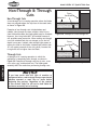
Non-Through & Through
Cuts
Non-Through Cuts
=\eZ\
JXn9cX[\
Nfibg`\Z\
A non-through cut is a sawing operation where the blade
does not protrude above the top face of the wood stock,
as shown in Figure 28.
Examples of non-through cuts include dadoes and
rabbets. Non-through cuts have a higher risk of injury
from kickback because the blade guard must be removed.
However, the riving knife MUST be installed because it
still provides some protection. When making non-through
cuts with a dado blade, do not attempt to cut the full
depth in one pass. Instead, take multiple light passes to
reduce the load on the blade. A dado blade smaller than
10" will require removal of the riving knife, because the
riving knife will be higher than the blade.
Figure 28. Example of a non-through cut.
=\eZ\
JXn9cX[\
Nfibg`\Z\
FG<I8K@FEJ
Through Cuts
A through cut is a sawing operation in which the
workpiece is completely sawn through, as shown in
Figure 29. Examples of through cuts are rip cuts, cross
cuts, miter cuts, and beveled cuts. The blade guard
assembly MUST be used when performing through cuts.
If you have never used this type of machine or
equipment before, seek training from an experienced
machine operator or read "how to" books before
beginning any projects. Regardless of the content
in this section, Shop Fox will not be held liable for
accidents caused by lack of training.
-24-
Figure 29. Example of a through cut.
Df[\cN(/)+('?pYi`[KXYc\JXn
Blade Size Requirements
When choosing a blade, make sure the blade size meets
the requirements listed below. The thickness of the
blade body and teeth can measured with calipers or any
precision measurement device.
Blade Size Requirements:
• Blade Diameter ......................................... 10"
• Body Thickness ..............0.071"–0.094" (1.8–2.4mm)
• Kerf (Tooth) Thickness .....0.102"–0.126" (2.6–3.2mm)
Using a blade that does not meet the specified blade
size requirements presents a hazardous condition
that could cause kickback, operator injuries, or
properly damage. ALWAYS use a blade that meets the
given blade size requirements.
=cXk
Kfg
9cX[\
Figure 30. Example of a ripping blade.
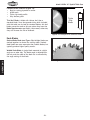
Blade Selection
8ck\ieXk\
Kfg
9\m\c
Ripping Blade Features (Figure 30):
• Best for cutting with the grain
• 20-40 teeth
• Flat-top ground tooth profile
• Large gullets for large chip removal
Crosscut Blade Features (Figure 31):
• Best for cutting across the grain
• 60-80 teeth
• Alternate top bevel tooth profile
• Small hook angle and a shallow gullet
Figure 31. Example of a crosscut blade.
Combination Blade Features (Figure 32):
• Designed to cut both with and across grain
• 40-50 teeth
• Alternate top bevel and flat, or alternate top bevel
and raker tooth profile
• Teeth are arranged in groups
• Gullets are small and shallow (similar to a cross-cut
blade), then large and deep (similar to a ripping
blade
8ck\ieXk\
Kfg
9\m\c
Xe[
=cXk
Figure 32. Example of a combination
blade.
-25-
FG<I8K@FEJ
This section on blade selection is by no means
comprehensive. Always follow the saw blade
manufacturer's recommendations to ensure safe and
efficient operation of your table saw.
Df[\cN(/)+('?pYi`[KXYc\JXn
Laminate Blade Features (Figure 33):
• Best for cutting plywood or veneer
• 40-80 teeth
• Triple chip tooth profile
• Very shallow gullet
Thin Kerf Blade: A blade with thinner kerf than a
standard blade. Since the spreader/riving knife included
with this table saw is sized for standard blades, thin kerf
blades cannot be used on this saw unless they meet the
Blade Requirements specified in this manual; otherwise,
they will increase the risk of kickback.
Ki`gc\
:_`g
9cX[\
Figure 33. Example of a laminate blade.
Dado Blades
Stacked Dado Blade (see Figure 34): Multiple blades are
stacked together to control the cutting width. Stacked
dado blades are more expensive than wobble blades, but
typically produce higher quality results.
Wobble Dado Blade: A single blade mounted at a slight
angle on an arbor hub. The blade angle is adjustable on
the hub, and the width of the dado cut is controlled by
the angle setting of the blade.
FG<I8K@FEJ
Figure 34. Stacked dado blade.
-26-
Df[\cN(/)+('?pYi`[KXYc\JXn
Blade Installation
Properly installing the blade is critical to safe cutting
operations that produce good results. Review this section,
even if your blade came pre-installed.
To install the blade, do these steps:
1.
DISCONNECT SAW FROM POWER!
2.
Remove the table insert and blade guard/riving
knife, depending on what is installed.
Before proceeding with the next step, wear leather
gloves to protect your hands while handling and
installing the blade.
Push the arbor lock in (see Figure 35) and turn the
blade until it locks in place, then use the arbor
wrench to loosen and remove the arbor nut, flange,
and blade.
4.
Slide the blade over the arbor with the teeth facing
the front of the saw, as shown in Figure 36.
5.
Re-install the arbor flange and the arbor nut, then
tighten them against the blade with the wrenches
included with the saw. DO NOT overtighten.
6.
Re-install the table insert and blade guard/riving
knife.
Arbor
Lock
Figure 35. Arbor lock location.
Figure 36. Order of blade component
installation and teeth facing to the front.
-27-
FG<I8K@FEJ
3.
The arbor nut is self-tightening by
design when a cut is made. When
installing the blade, only tighten the
arbor nut so that it firmly holds the
blade in place. Overtightening the
arbor nut may lead to nut and arbor
failure which could cause metal debris
to be thrown from the saw.
Df[\cN(/)+('?pYi`[KXYc\JXn
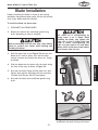
Blade Guard Assembly
The term "blade guard" refers to the assembly that
consists of the clear polycarbonate shield, the spreader,
and the anti-kickback pawls on each side of the spreader
(see Figure 37). Each of these components have
important safety functions during the operation of the
saw.
Guard
Clear Guard
Spreader
The clear polycarbonate guard allows the operator to
see the blade cut the workpiece during operation. This
guard is designed to lift as the workpiece is pushed into
the blade and remain in contact with the workpiece
throughout the entire cut.
Anti-Kickback
Pawl
Figure 37. Blade guard assembly
components.
The guard reduces injury risk by providing a barrier
around the blade that prevents accidental contact and
contains flying wood chips.
FG<I8K@FEJ
To ensure that the guard does its job effectively, the
guard must always be in the downward position against
the table during idle operation, and the hinge mechanism
must be maintained in good working condition so the
guard can freely pivot up and down to accommodate the
height of the workpiece and return to the table surface.
Spreader
The spreader is a metal plate that prevents the freshly
cut pieces of the workpiece from pinching the backside of
the blade and causing a kickback. It also acts as a barrier
behind the blade to shield hands from being pulled into
the blade if a kickback occurs.
In order to work properly, the spreader
cannot be bent or misaligned with the
blade. If the spreader gets accidentally
bent, take the time to straighten it
or just replace it. Using a bent or
misaligned spreader will increase the
risk of kickback!
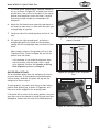
Blade Guard & Spreader Installation
Bracket
1.
DISCONNECT SAW FROM POWER!
2.
Install the standard table insert.
3.
Slide the knurled knob out (see Figure 38), then
rotate it so it engages the upper bracket.
4.
5.
Locking
Pin
Slide the blade guard spreader all the way down
into the adjustment block, then rotate the knurled
knob so it disengages the bracket and the locking pin
engages the hole in the center of the spreader.
Tug the spreader upward to verify that it is locked
and does not come out when pulled.
-28-
Knurled
Knob
Adjustment
Block
Figure 38. Knurled knob used to secure
the spreader.
Df[\cN(/)+('?pYi`[KXYc\JXn
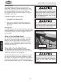
The blade guard, when properly installed, should be
set up, as shown in Figure 39. It should pivot freely
up and down, then return to the table in the resting
position and completely cover the blade. It should
also swing up high enough to accommodate the
workpiece.
6.
Adjust the flat head screws around the perimeter of
the insert to make sure it is flush with the table (use
a straightedge as a guide).
7.
Swing one side of the blade guard up and out of the
way.
8.
Lift up on the right spreader pawl, and place a
straightedge against the blade and the spreader,
making sure the straightedge does not touch a blade
tooth.
When properly aligned, the spreader will be in the
"Alignment Zone," shown in Figure 40, and will be
parallel with the blade.
— If the spreader is not inside the alignment zone
and not parallel with the blade, then it needs
to be adjusted. Perform the Spreader or Riving
Knife Alignment procedure on Page 63.
The anti-kickback pawls allow the workpiece to travel in
only one direction. If the workpiece moves backwards,
such as during a kickback, the pawls will dig into the
workpiece to slow or stop it.
To work properly, the pawls must return to their resting
position after pivoting up, as shown in Figure 41, and
they must not be engaged in the arresting hooks.
8c`^ed\ek
Qfe\
Jgi\X[\ifi
I`m`e^Be`]\
9cX[\
JkiX`^_k\[^\
Figure 40. Spreader in the "Alignment
Zone."
Arresting Hooks
Pawl
If the pawls fail to return to the resting position, the pivot
area may need to be cleaned or the spring may have been
dislodged or broken and will need to be fixed/replaced.
Figure 41. Pawls in the resting position.
-29-
FG<I8K@FEJ
Anti-Kickback Pawls
Figure 39. Blade guard and spreader
properly installed.
Df[\cN(/)+('?pYi`[KXYc\JXn
Disabling Pawls
You might disable the pawls if you are concerned
about them scratching a delicate workpiece, or if you
believe that they will obstruct a narrow workpiece and
cause feeding difficulty or loss of control. Use your
best judgment before retracting the pawls, as they are
provided for your safety.
To disable the pawls, do these steps:
1.
DISCONNECT SAW FROM POWER!
2.
Rotate one or both arresting hooks downward,
then place the pawls on each of the hooks (see
Figure 42).
Enabling Pawls
To enable the pawls, lift up on each pawl and move them
outward and down until they both touch the table surface
in the resting position, as shown in Figure 41 on the
previous page.
We do not recommend disabling the
pawls during normal operations unless
absolutely necessary. In most situations,
disabling the pawls will increase your
risk of serious personal injury in the
event of a kickback.
The pawls are sharp and can quickly
cut fingers and hands. Use caution, and
wear leather gloves when handling the
pawls to reduce the risk of injury.
FG<I8K@FEJ
When to Use the Blade Guard
The blade guard assembly MUST always be installed on
the saw for all normal through cuts (those where the
blade cuts all the way through the thickness of the
workpiece). If the blade guard is removed for specific
operations, always immediately replace it after those
operations are complete.
Arresting Hook
(1 of 2)
Pawl
When Not to Use the Blade Guard
The blade guard cannot be used on any non-through
cuts (those in which the blade does not cut all the way
through the thickness of the workpiece).
Sometimes the blade guard or its components can get in
the way when cutting very narrow workpieces or other
specialized cuts. Because the blade guard is provided to
decrease your risk of injury, it should not be used if it
gets in the way of making a safe cut. Use good judgment!
-30-
Figure 42. Pawl disabled.
Whenever the blade guard and spreader
cannot be used, the riving knife must
be used to avoid the risk of the kerf
binding on the blade and causing
kickback.
Df[\cN(/)+('?pYi`[KXYc\JXn
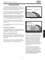
Riving Knife
The riving knife works in the same manner as the
spreader on the blade guard assembly. It is a metal plate
that prevents the newly cut workpiece from pinching the
backside of the blade and causing kickback.
D`e`dld(dd
DXo`dld,dd
?\`^_k;`]]\i\eZ\
The key difference between the spreader and the riving
knife is that the riving knife mounts below the blade's
highest point of rotation, as shown in Figure 43.
The height difference between the riving knife and the
blade allows the workpiece to pass over the blade during
non-through cuts (those in which the blade does not cut
all the way through the thickness of the workpiece).
The riving knife acts as a barrier behind the blade to
reduce the risk of hands being pulled into the blade if a
kickback occurs.
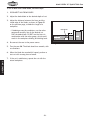
The riving knife must be spaced away from the blade, as
shown in Figure 44.
Riving Knife Installation
Figure 43. Height difference between the
riving knife and blade.
Kfg;`jkXeZ\
D`e`dld*dd
DXo`dld/dd
9fkkfd;`jkXeZ\
D`e`dld*dd
DXo`dld/dd
I`m`e^
Be`]\
KXYc\
Figure 44. Allowable distance ranges
between the riving knife and blade.
When to Use the Riving Knife
Use the riving knife for all non-through cuts made with a
standard table saw blade (i.e., dadoes or rabbet cuts, and
when using a tenoning jig), or when using a 10" diameter
dado blade.
Also, use the riving knife for those special operations
where the blade guard or its components get in the way
of safe operation, such as with very narrow cuts.
When Not to Use the Riving Knife
Do not use the riving knife with a dado
blade that has a diameter smaller than 10"
in diameter. Otherwise, the riving knife
height will exceed the blade height and
the workpiece will hit the riving knife
during the cut, forcing the operator into
a dangerous situation of trying to turn the
saw off with the workpiece stuck halfway
through the cut.
In addition, although it is possible to
use the riving knife for through-cutting
operations, the blade guard assembly offers
much more injury protection and risk
reduction than the riving knife. Therefore,
we strongly recommend that you use the
blade guard assembly instead of the riving
knife when making through cuts.
-31-
FG<I8K@FEJ
The riving knife is installed in a similar manner to the
blade guard and spreader. Refer to Blade Guard Assembly
on Page 28 for installation instructions.
I`m`e^
Be`]\
Df[\cN(/)+('?pYi`[KXYc\JXn
Ripping
Ripping means cutting with the grain of a natural wood
workpiece. In man-made materials such as MDF or
plywood, ripping simply means cutting lengthwise.
FG<I8K@FEJ
To make a rip cut, do these steps:
1.
Review Preventing Kickback on Page 9 and take the
necessary precautions to reduce the likelihood of
kickback.
2.
Inspect the board for soundness. You will need one
straight edge of the workpiece to place against the
fence when ripping. Also, if the workpiece is slightly
cupped, always place the cupped side down on the
table for stability.
3.
DISCONNECT SAW FROM POWER!
4.
Ensure that the blade guard/spreader is properly
installed.
5.
Set the fence to the desired width of cut on the
scale.
6.
Adjust the blade height so the highest saw tooth
protrudes no more than 1⁄4" above the workpiece.
7.
Set up safety devices such as featherboards or other
anti-kickback devices.
8.
Rotate the blade to make sure it does not come into
contact with any of the safety devices.
9.
Re-connect the saw to power, then turn it ON and
allow the blade to reach full speed.
Never attempt to rip a workpiece that
does not have one perfectly straight
edge on it. Always place the straight
edge against the rip fence. Failure to
do this could result in kickback and
serious personal injury.
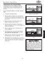
Figure 45. Example photo of a ripping
operation.
Note: The jointed edge of the workpiece must slide
against the fence during the cutting operation.
10. Use a push stick to feed the workpiece through
the saw blade, as shown in Figure 45, until it is
completely beyond the saw blade.
Keep the blade guard installed and in
the down position. Failure to do this
could result in serious personal injury
or death.
Turn OFF the saw and ALWAYS allow
the blade to come to a complete stop
before removing the cut-off piece.
Failure to follow this warning could
result in serious personal injury.
-32-
Df[\cN(/)+('?pYi`[KXYc\JXn
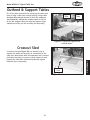
Crosscutting
Crosscutting means cutting across the grain of a natural
wood workpiece. In other man-made materials, such as
MDF or plywood, crosscutting means cutting across the
width of the workpiece.
To make a crosscut using the miter gauge, do these
steps:
DISCONNECT SAW FROM POWER!
2.
Ensure that the blade guard/spreader is properly
installed.
3.
Move the rip fence aside and position the miter
gauge in a miter slot, then adjust it to 90° from the
blade.
4.
Adjust the blade height so the teeth protrude no
more than 1⁄4" above the workpiece.
5.
Inspect the workpiece for soundness. If the
workpiece is slightly cupped, place the cupped face
down on the table.
6.
Slide the miter gauge near the blade and adjust the
workpiece so the blade will cut on the waste side of
the line.
7.
Re-connect the saw to power, then turn it ON and
allow the blade to reach full speed.
8.
Hold the workpiece firmly against the face of the
miter gauge (as shown in Figure 46), then ease the
workpiece through the blade until it is completely
past the saw blade.
-33-
Figure 46. Example photo of a
crosscutting operation.
FG<I8K@FEJ
1.
Df[\cN(/)+('?pYi`[KXYc\JXn
Miter Cuts
A miter cut is an angled crosscut. Miters are usually cut in
the same manner as crosscuts, using the miter gauge and
a predetermined mark on the workpiece.
FG<I8K@FEJ
To perform a miter cut, do these steps:
1.
DISCONNECT SAW FROM POWER!
2.
Ensure that the blade guard/spreader is properly
installed.
3.
Determine the angle of your cut. If the angle needs
to be very precise, use a protractor to set the miter
gauge to the blade.
4.
Place the face of the miter gauge against the edge
of the workpiece and place the T-slot bar across
the face of the workpiece. Use the bar as a guide
to mark your cut onto the workpiece, as shown in
Figure 47.
5.
Place the miter gauge back into the slot and hold
the workpiece firmly against the miter gauge body.
Slide the miter gauge near the blade and adjust the
workpiece so the blade will cut on the waste side of
the line.
6.
Proceed to make the cut in the same manner as
described in the Crosscutting procedure.
Figure 47. Example photo of making a
miter mark.
Blade Tilt Cuts
The blade can be tilted between 0° (perpendicular to
the table) and 45°. This feature is used most often when
cutting bevels, compound miters, or chamfers. Figure 48
shows an example of the blade when tilted 45° to the
table.
-34-
Figure 48. Blade tilted 45° to the table.
Df[\cN(/)+('?pYi`[KXYc\JXn
Dado Cutting
Commonly used in furniture joinery, a dado is a straight
channel cut in the face of the workpiece. Dadoes are
"non-through" cuts that can be made with a dado blade or
a standard saw blade. Figure 49 shows a cutaway view of
a dado cut being made with a dado blade.
The included dado table insert must be installed and used
when a dado blade is installed—unless a zero clearance
table insert is used instead.
;X[f9cX[\
=\eZ\
Nfibg`\Z\
Dado Blade Installation
Figure 49. Illustration of a dado cut.
1.
DISCONNECT SAW FROM POWER!
2.
Remove the standard table insert, the blade guard
assembly or riving knife, and the saw blade.
3.
Attach and adjust the dado blade system according
to the dado blade manufacturer’s instructions
4.
Install the dado table insert.
Dado Blade
Cut 1
Fence
Workpiece
Cut 2
Fence
Workpiece
Cutting Dados with a Dado Blade
Because dado blades are much wider than standard
blades, they place a greater amount of force against the
workpiece when cutting. This additional force increases
the risk of kickback, requiring the operator to take
additional steps when cutting to keep their injury risk at
an acceptable level.
Figure 50 demonstrates the sequential process of making
multiple, light cuts that get progressively deeper. The
actual number of cuts used should be determined by
workpiece hardness, total dado depth, and feed rate. In
general, if you hear the motor slow down during the cut,
you are cutting too deep or feeding too fast.
Cut 3
Workpiece
Fence
Finished
Dado Cut
Workpiece
Fence
Figure 50. Example of cutting a dado with
multiple light cuts, instead of one deep
cut.
-35-
FG<I8K@FEJ
Dado blades have a higher risk of kickback than
normal blades because their larger size applies
stronger forces to the workpiece. This risk increases
relative to the depth and width of the cut. To
minimize your risk of serious personal injury, ensure
that stock is flat and straight, and make multiple
light cuts (rather than one deep cut) to achieve the
desired cutting depth.
DO NOT make through cuts with a dado
blade. Dado blades are only intended
for non-through cuts. Failure to heed
this warning could result in serious
injury.
Df[\cN(/)+('?pYi`[KXYc\JXn
To cut a dado with a dado blade, do these steps:
1.
DISCONNECT SAW FROM POWER!
2.
Adjust the dado blade to the desired depth of cut.
3.
Adjust the distance between the fence and the
inside edge of the blade, as shown in Figure 51
on the previous page, to dado the length of a
workpiece.
— If dadoing across the workpiece, use the miter
gauge and carefully line up the desired cut
with the dado blade. DO NOT use the fence in
combination with the miter gauge, which could
result in the workpiece binding and kicking back.
4.
Re-connect the saw to the power source.
5.
Turn the saw ON. The blade should run smooth, with
no vibrations.
6.
When the blade has reached full speed, perform a
test cut with a scrap piece of wood.
7.
If the cut is satisfactory, repeat the cut with the
actual workpiece.
;X[f9cX[\
=\eZ\
Nfibg`\Z\
FG<I8K@FEJ
Figure 51. Illustration of a dado cut.
-36-
Df[\cN(/)+('?pYi`[KXYc\JXn
Cutting Dados with a Standard Blade
A ripping blade (described on Page 25) is typically
the best blade to use for cutting dadoes when using
a standard blade, because it removes sawdust very
efficiently.
Cut 1
Blade
Fence
Workpiece
To use a standard saw blade to cut dadoes, do these
steps:
Figure 52. First cut when using a single
blade for making a dado.
1.
DISCONNECT SAW FROM POWER!
2.
Mark the width of the dado cut on the workpiece.
Include marks on the edge of the workpiece so the
cut path can be aligned when the workpiece is lying
on the table.
Cut 2
Blade
Fence
Raise the blade up to the desired depth of cut
(depth of the dado channel desired).
Workpiece
4.
Set up the saw for the type of cut you need to
make, depending on if it is a rip cut (see Page 32) or
crosscut (see Page 33).
Figure 53. Second cut for a single dado
cut.
5.
Align the blade to cut one of the dado sides, as
shown in Figure 52.
6.
Re-connect the saw to the power source and turn
the saw ON. Allow the blade to reach full speed,
then perform the cutting operation.
7.
8.
Repeat the cutting operation on the other side of
the dado channel, as shown in Figure 53.
Make additional cuts (see Figure 54) in the center
of the dado to clear out the necessary material. The
dado is complete when the channel is completely
cleared out.
Cuts 3+
=\eZ\
Nfibg`\Z\
Figure 54. Additional single blade dado
cuts.
Always use push sticks, featherboards,
push paddles and other safety
accessories whenever possible to
increase safety and control during
operations which require that the
blade guard be removed from the saw.
ALWAYS replace the blade guard after
dadoing is complete.
-37-
FG<I8K@FEJ
3.
Df[\cN(/)+('?pYi`[KXYc\JXn
Rabbet Cutting
Commonly used in furniture joinery, a rabbet cut is
an L-shaped groove cut in the edge of the workpiece.
Rabbets can be cut with either a dado blade or a standard
saw blade.
Rabbet cutting on the edge of the workpiece with a dado
blade requires a sacrificial fence (see Figure 55). Make
the sacrificial fence the same length as the fence and
3
⁄4" thick. Attach it to the fence with screws or clamps,
making sure they are all secure and tight. Raise the blade
into the sacrificial fence to the height needed.
FG<I8K@FEJ
Cutting Rabbets with a Dado Blade
1.
DISCONNECT SAW FROM POWER!
2.
Adjust the dado blade to the height needed for the
rabbeting operation. When cutting deep rabbets,
take multiple light passes to reduce the risk of
kickback.
3.
Adjust the fence and align the workpiece to perform
the cutting operation, as shown in Figure 56.
4.
Re-connect the saw to the power source and turn
the saw ON. When the blade has reached full speed,
perform a test cut with a scrap piece of wood.
Dado blades have a higher risk of
kickback than normal blades because
their larger size applies stronger forces
to the workpiece. This risk increases
relative to the depth and width of the
cut. To minimize your risk of serious
personal injury, ensure that stock is
flat and straight, and make multiple
light cuts (rather than one deep cut) to
achieve the desired cutting depth.
I`g=\eZ\
JXZi`]`Z`Xc=\eZ\
;X[f@ej\ik
9cX[\:lk$Flk
Figure 55. Sacrificial fence installed.
— If the cut is satisfactory, repeat the cut with the
final workpiece.
Sacrificial Fence
Dado Blade
Fence
Workpiece
Figure 56. Rabbet cutting with a
sacrificial fence.
-38-
Df[\cN(/)+('?pYi`[KXYc\JXn
Cutting Rabbets with a Standard Blade
A ripping blade is typically the best blade to use for
cutting rabbets when using a standard blade because it
removes sawdust very efficiently. (See Page 25 for blade
details.) Also, a sacrificial fence is not required when
cutting rabbets with a standard blade.
To cut rabbets with the standard blade, do these steps:
1.
DISCONNECT SAW FROM POWER!
2.
Ensure that the riving knife and standard table insert
are properly installed.
3.
Mark the width of the rabbet cut on the edge of the
workpiece, so you can clearly identify the intended
cut while it is laying flat on the saw table.
4.
Raise the blade up to the desired depth of cut
(depth of the rabbet channel desired).
5.
Stand the workpiece on edge, as shown in Figure 57,
then adjust the fence so the blade is aligned with
the inside of your rabbet channel.
45
15
30
DO NOT place a tall board on edge to
perform a rabbet cut with a standard
blade. Workpieces that are too tall
to be properly supported with the
fence can easily shift during operation
and cause kickback. Instead, place the
stock flat on the saw and perform the
rabbet cut with a dado blade.
Reconnect the saw to the power source, then
perform the cut.
7.
Lay the workpiece flat on the table, as shown in
Figure 58, adjust the saw blade height to intersect
with the first cut, then perform the second cut to
complete the rabbet.
Blade
Workpiece
6.
FG<I8K@FEJ
— If the workpiece is very tall, or is unstable when
placed against the fence, lay it flat on the table
and use a dado blade to perform the rabbet cut.
Fence
Figure 57. First rabbet cut with a single
blade.
Blade
Fence
Workpiece
Figure 58. Second rabbet cut with a single
blade.
-39-
Df[\cN(/)+('?pYi`[KXYc\JXn
Resawing
Resawing is the process of cutting a thick piece of stock
into one or more thinner pieces. Although resawing can
be done with a table saw, we strongly recommend that
you use a bandsaw instead.
A bandsaw is the ideal machine for resawing, and
resawing with one is fairly easy and safe. A table saw
is not intended for resawing, and resawing with one
is difficult and dangerous due to the increased risk of
kickback from binding and deep cuts, and the increased
risk of injury from having to remove the guard.
If you insist on resawing with a table saw, DO NOT do
so without using a resaw barrier and wearing a full face
shield. The following instructions describe how to build a
resaw barrier and add an auxiliary fence to your standard
fence, to reduce the risk injury from resawing on a table
saw.
Note: To determine the maximum resawing height for this
table saw, find the maximum blade height, then double it
and subtract 1⁄8".
FG<I8K@FEJ
Making a Resaw Barrier
The resaw barrier acts in tandem with the rip fence when
resawing to provide tall support for the workpiece to
minimize the probability of it binding against the blade
and causing kickback.
Tools Needed:
Qty
Table Saw ........................................................1
Jointer and Planer ............................. Recommended
Clamps ................................................2 Minimum
Drill and Drill Bits ................................... As Needed
Components Needed for Resaw Barrier:
Wood* 3⁄4" x 5 1⁄2" x Length of Fence ........................1
Wood* 3⁄4" x 3" x Length of Fence............................1
Wood Screws #10 x 2" .........................................4
Wood Glue ........................................... As Needed
* Only use furniture-grade plywood, kiln dried hardwood,
or HDPE plastic to prevent warping.
-40-
Resawing operations require proper
procedures to avoid serious injury.
Extra care must be taken to prevent
kickback when resawing. Any tilting
or movement of the workpiece away
from the fence will cause kickback. Be
certain that stock is flat and straight.
Failure to follow these warnings could
result in serious personal injury.
Df[\cN(/)+('?pYi`[KXYc\JXn
To build the resaw barrier, do these steps:
1.
2.
Cut your wood pieces to the size specified above.
If you are using hardwood, cut the pieces oversize,
then joint and plane them to the correct size to
make sure they are square and flat.
#10 x 2"
Wood Screw
3
⁄4"
Pre-drill and countersink four holes approximately
⁄8" from the bottom of the 5 1⁄2" tall wood piece.
3
3.
Glue the end of the 3" board, then clamp the boards
at a 90° angle with the larger board in the vertical
position, as shown in Figure 59, and fasten them
together with the wood screws.
3
⁄4"
Assembled
Resaw Barrier
Figure 59. Shop-made resaw barrier.
Auxiliary Fence
The auxiliary fence is necessary if you are resawing a
workpiece that is taller than it is wide. It should be no
less than 1⁄2" shorter than the board to be resawn.
Components Needed for the Auxiliary Fence:
Wood* 3⁄4" x (Height) x Length of Fence ....................1
* Only use furniture-grade plywood, kiln dried hardwood,
or HDPE plastic to prevent warping.
FG<I8K@FEJ
Tools Needed for the Auxiliary Fence:
Table Saw ........................................................1
Jointer and Planer ............................. Recommended
Clamps ................................................2 Minimum
To build the auxiliary fence, do these steps:
1.
Cut the auxiliary fence board to size. If you are using
hardwood, cut the board oversize, then joint and
plane the board to the correct size to make sure the
board is square and flat.
2.
Unthread the fence face mounting hardware and
remove the fence face from the fence assembly.
3.
Place the auxiliary fence next to the fence face you
removed in Step 1, mark the location of the nine
mounting holes on the auxiliary fence, then drill the
holes.
4.
Use the mounting hardware you removed in Step 2
to attach the auxiliary fence. The end result should
be similar to Figure 60.
-41-
Fence
Facing
Fence
Body
Auxiliary
Fence
Figure 60. Example illustration of an
auxiliary fence installed.
Df[\cN(/)+('?pYi`[KXYc\JXn
Resawing Operation
The table saw motor is pushed to its limits when
resawing. If the motor starts to bog down, slow down
your feed rate. Motor overloading and blade wear can
be reduced by using a ripping blade. Ripping blades are
designed to clear the sawdust quickly.
The risk of kickback when resawing is
high. Always stand to the side of the
cutting path and wear a full face shield
to prevent kickback injuries when
resawing.
Components Needed for Resawing:
Zero-clearance Table Insert ...................................1
Ripping Blade 10" ...............................................1
Clamps ............................................................2
Shop Made Auxiliary Fence ....................................1
Shop Made Resaw Barrier ......................................1
FG<I8K@FEJ
To perform resawing operations, do these steps:
1.
DISCONNECT SAW FROM POWER!
2.
Remove the standard table insert and the blade
guard assembly.
3.
Install a ripping blade, install the riving knife,
lower the blade below the table, then install a zero
clearance table insert.
4.
Attach the auxiliary fence and set it to the desired
width from the blade.
Note: When setting the correct width, don't forget
to account for blade kerf and the inaccuracy of the
fence scale while the auxiliary fence is installed.
5.
Place the workpiece against the auxiliary fence and
slide the resaw barrier against the workpiece, as
shown in Figure 61. Now clamp the resaw barrier to
the top of the table saw at both ends.
6.
Lower the blade completely below the table, slide
the workpiece over the blade to make sure it moves
smoothly and fits between the resaw barrier and
fence, then remove the workpiece.
7.
Raise the blade approximately an inch, or close to
half the height of the workpiece, whichever is less.
-42-
Nfibg`\Z\
I\jXn
9Xii`\i
(Front View)
8lo`c`Xip
=\eZ\
=\eZ\
Figure 61. Example illustration of a resaw
setup.
Df[\cN(/)+('?pYi`[KXYc\JXn
8.
9.
Plug in the table saw, turn it ON, and use a push
stick or push block to feed the workpiece through
the blade, using a slow and steady feed rate.
Flip the workpiece end for end, keeping the same
side against the fence, and run the workpiece
through the blade again.
10. If necessary to complete the operation, repeat Steps
7–9 until the blade is close to half of the height of
the board to be resawn. The ideal completed resaw
cut will leave an 1⁄8" connection when the resawing
is complete, as shown in Figure 62. Leaving an 1⁄8"
connection will reduce the risk of kickback.
11. Turn OFF the table saw, then separate the parts of
the workpiece and hand plane the remaining ridge to
remove it.
The danger of kickback increases
relative to the depth of a cut. Reduce
the risk of kickback by making multiple
passes to achieve the desired depth of
cut. Failure to follow these warnings
could result in serious personal injury.
Always use push sticks or push paddles
to increase safety and control during
operations which require that the blade
guard and spreader must be removed
from the saw. ALWAYS replace the blade
guard after resawing is complete.
12. When finished resawing, remove the resaw barrier
and auxiliary fence, then re-install the blade guard/
spreader or riving knife and standard table insert.
Nfibg`\Z\
I\jXn
9Xii`\i
8lo`c`Xip
=\eZ\
=\eZ\
&/:fee\Zk`fe
Figure 62. Completed resaw operation.
-43-
FG<I8K@FEJ
(
Df[\cN(/)+('?pYi`[KXYc\JXn
SHOP-MADE SAFETY ACCESSORIES
Featherboards
Easily made from scrap stock, featherboards provide an
added degree of protection against kickback, especially
when used together with push sticks. They also maintain
pressure on the workpiece to keep it against the fence
or table while cutting, which makes the operation easier
and safer because the cut can be completed without the
operator’s hands getting near the blade. The angled ends
and flexibility of the fingers allow the workpiece to move
in only one direction.
Making a Featherboard
This sub-section covers the two basic types of
featherboards: 1) Those secured by clamps, or 2) those
secured with the miter slot.
FG<I8K@FEJ
Material Needed for Featherboard:
Hardwood 3⁄4" x 3" x 10" (Minimum) .........................1
Hardwood 3⁄4" x 6" x 28" (Maximum).........................1
Additional Material Needed for Mounting Featherboard:
Hardwood 3⁄8" x (Miter Slot Width) x 5"L ...................1
Wing Nut 1⁄4"-20 .................................................1
Flat Head Screw 1⁄4"-20 x 2" ..................................1
Flat Washer 1⁄4"-20 .............................................1
Cuts made across the grain result in
weak fingers that easily break when
flexed. When made correctly, the
fingers should withstand flexing from
moderate pressure. To test the finger
flexibility, push firmly on the ends with
your thumb. If the fingers do not flex,
they are likely too thick (the cuts are
too far apart).
10" (Minimum)
3
30°
Kerf
1
/16"-1/8"
/8"
A
2"-3"
To make a featherboard, do these steps:
Initial Cut
2"-3"
1.
Cut a hardwood board that is approximately 3⁄4"
thick to size. The length and width of the board can
vary according to your design. Most featherboards
are 10"–28" long and 3"–6" wide. Make sure the
wood grain runs parallel with the length of the
featherboard, so the fingers you will create in
Step 3 will bend without breaking.
2.
Cut a 30º angle at one end of the board.
3.
Make a series of end cuts with the grain 3⁄8"– 1⁄4"
apart and 2"–3" long, as shown in Figure 63
(A). Alternatively, start cuts at 2"–3" deep, then
make them progressively deeper, as shown in
Figure 63 (B).
-44-
1
3
B
Kerf
/16"-1/8"
/ 8"
Progressively
Longer Cuts
Figure 63. Patterns for making
featherboards.
Only Steps 1–3 are required to make a
clamp-mounted featherboard. Refer to
Page 46 for instructions on clamping
the featherboard to the table.
Df[\cN(/)+('?pYi`[KXYc\JXn
4.
5.
Rout a 1⁄4"– 3⁄8" wide slot 4"–5" long in the workpiece
and 1"–2" from the short end of the featherboard, as
illustrated in Figure 64.
1"-2"
Drill a 1⁄4" hole in the center of the bar, then
countersink the bottom to fit a 1⁄4"-20 flat head
screw.
4"-5"
Figure 64. Slot cut into the featherboard
for use with a miter slot.
(Top View)
3
7.
8.
/4"-3/8" Slot
Cut a miter bar that will fit in the table miter slot
approximately 5" long (see Figure 65).
Tip: Consider making the miter bar longer for larger
featherboards—approximately half the length of the
total featherboard—to support the force applied to
the featherboard during use.
6.
1
Mark a 4" line through the center of the countersunk
hole in the center, then use a jig saw with a narrow
blade to cut it out.
5"
Assemble the miter bar and featherboard with a 1⁄4"20 x flat head screw, flat washer, and a wing nut or
a star knob (see Figure 66). Congratulations! Your
featherboard is complete.
Tip: The length of the flat head screw depends on
the thickness of the featherboard—though 1 1⁄2" to 2"
lengths usually work.
/8"
1
/4" Hole
Countersink on Bottom
4" Slot
Figure 65. Patterns for featherboard miter
bar.
Wing Nut
(Side View)
Flat Washer
Featherboard
Miter Bar
Flat Head Screw
9.
Proceed to Mounting Featherboard in Miter Slot on
the next page.
-45-
Figure 66. Assembly order of featherboard
components for use with a miter slot.
FG<I8K@FEJ
Note: The routed slot, countersunk hole, and the
flat head screw are essential for the miter bar to
clamp into the miter slot. When the wing nut is
tightened, it will draw the flat head screw upward
into the countersunk hole. This will spread the sides
of the miter bar and force them into the walls of
the miter slot, locking the featherboard in place.
(Side View)
5"
Df[\cN(/)+('?pYi`[KXYc\JXn
Mounting Featherboard with Clamps
1.
DISCONNECT SAW FROM POWER!
2.
Lower the saw blade, then adjust the fence to the
desired width and secure it.
3.
Place the workpiece against the fence, making sure
it is 1" in front of the blade.
4.
Place a featherboard on the table so all fingers
point forward and contact the workpiece evenly (see
Figure 67 for an example).
Fence Featherboard
Clamp
5.
Secure the featherboard to the table with a clamp.
6.
Check the featherboard by pushing it with your
thumb to ensure it is secure.
Clamp
— If the featherboard moves, tighten the clamp some
more.
7.
Mount a second featherboard to the fence with
another clamp, then repeat Step 6 to ensure it is
secure (see Figure 67).
Table
Featherboard
Figure 67. Example photo of
featherboards mounted with clamps.
FG<I8K@FEJ
Mounting Featherboard in Miter Slot
1.
DISCONNECT SAW FROM POWER!
2.
Lower the saw blade, then adjust the fence to the
desired width and secure it.
Blade
3.
Place the workpiece evenly against the fence,
making sure it is 1" in front of the blade.
4.
Slide the featherboard miter bar into the miter slot,
making sure the fingers slant toward the blade, as
illustrated in Figure 68.
5.
6.
Position the fingered edge of the featherboard
against the edge of the workpiece, so that all of
the fingers contact the workpiece evenly. Slide the
featherboard toward the blade until the first finger
is nearly even with the end of the workpiece, which
should be 1" away from the blade.
Double check the workpiece and the featherboard to
ensure they are properly positioned, as described in
Step 5. Then secure the featherboard to the table.
Check the featherboard by hand to make sure it is
tight.
-46-
Featherboard
Workpiece
Figure 68. Example illustration of the
featherboard mounted in the miter slot.
The featherboard should be placed
firmly enough against the workpiece
to keep it against the fence but not
so tight that it is difficult to feed the
workpiece.
Df[\cN(/)+('?pYi`[KXYc\JXn
Push Sticks
Push Stick
Prohibition
Zone
When used correctly, push sticks reduce the risk of injury
by keeping hands away from the blade while cutting. In
the event of an accident, a push stick can absorb damage
that would have otherwise happened to hands or fingers.
Use push sticks whenever your hands will get within 12"
of the blade. To maintain control when cutting large
workpieces, start the cut by feeding with your hands then
use push sticks to finish the cut, so your hands are not on
the end of the workpiece as it passes through the blade.
Push Stick
Store Push
Stick Here
for Easy
Access
Supporting
Blade
Path
Push Stick
Feeding
Feeding: Place the notched end of the push stick
against the end of the workpiece (see inset Figure 69),
and move the workpiece into the blade with steady
downward and forward pressure.
=`^li\-0% Using push sticks to rip narrow
stock.
Supporting: A second push stick can be used to keep the
workpiece firmly against the fence while cutting. When
using a push stick in this manner, only apply pressure
before the blade; otherwise, pushing the workpiece
against or behind the blade will increase the risk of
kickback (see Figure 69).
=`^li\.'% Side view of push stick in-use.
Making a Push Stick
FG<I8K@FEJ
Use this template to make
your own push stick.
90º
15 3
/4 "
Mi
nim
um
Le
ng
Cut here to
push 1⁄4" stock
th
SIZING: Push stick must
be at least 15 3⁄4" long.
Use 1⁄2"–3⁄4" thick
material.
Cut here to push 1⁄2" stock
Notch for placing on
corners of workpieces
1
⁄2" Grid
Notch to help
prevent hand
from slipping
MATERIAL: Only use hardwood, sturdy plywood, or
high-density plastic. Do not
use softwood that may break
under pressure or metal that
can break teeth from the
blade!
SANDING: Sand
edges to remove
rough edges and
increase comfort.
Figure 71. Template for a basic shop-made push stick (not shown at actual size).
-47-
Df[\cN(/)+('?pYi`[KXYc\JXn
Push Blocks
When used correctly, a push block reduces the risk of
injury by keeping hands away from the blade while
cutting. In the event of an accident, a push block often
takes the damage that would have otherwise happened
to hands or fingers.
A push block can be used in place of or in addition to
a push stick for feeding workpieces into the blade. Due
to their design, push blocks allow the operator to apply
firm downward pressure on the workpiece that could not
otherwise be achieved with a push stick.
Push Stick
Prohibition
Zone
Push Stick
Supporting
Blade
Path
Feeding
Push
Block
=`^li\.)% Using a push block and push
stick to make a rip cut.
The push block design on this page (see Figure 74) can
be used in two different ways (see Figure 73). Typically,
the bottom of the push block is used until the end of the
workpiece reaches the blade.
The notched end of the push block is then used to push
the workpiece the rest of the way through the cut,
keeping the operator's hands at a safe distance from the
blade. A push stick is often used at the same time in the
other hand to support the workpiece during the cut.
FG<I8K@FEJ
=`^li\.*. Side view of push block in use.
CAUTION: Bottom
of handle must be
at least 4" above
bottom of push
block to keep
hand away from
blade.
Making a Push Block
Use this template to make your own push block.
Handle for
firm grip
Make push block with
1
⁄2"–3⁄4" thick material
Notch for use
as a push stick
4"
CAUTION: Only use hardwood, sturdy plywood, or
high-density plastic. Do not use softwood that
may break under pressure or metal that can break
teeth from the blade!
1
⁄4"–1⁄2"
Lip for pushing workpiece
1
⁄2" Grid
9"−10" Minimum Length
Figure 74. Template for a basic shop-made push stick (not shown at actual size).
-48-
Df[\cN(/)+('?pYi`[KXYc\JXn
Narrow-Rip Auxiliary
Fence & Push Block
There are hundreds of designs for specialty jigs that can
be found in books, trade magazines, and on the internet.
These types of jigs can greatly improve the safety and
consistency of cuts. They are particularly useful during
production runs when dozens or hundreds of the same
type of cut need to be made. The narrow-rip auxiliary
fence and push block system shown in this section is an
example of a specialty jig that can be made to increase
the safety of very narrow rip cuts.
Material Needed for Narrow Rip Auxiliary Fence & Push
Block
Hardwood 3⁄4" x 3" x Length of Fence .......................1
Plywood 3⁄4" x 5 1⁄4" x Length of Fence ......................1
Wood Screws #8 x 11⁄2" .......................................8
Material Needed for Push Block
Hardwood or Plywood 3⁄4" x 15" x 5 5⁄8" .....................1
Hardwood or Plywood 3⁄4" x 10" x 5"–9" ....................1
Wood Glue .................................................Varies
Wood Screws #8 x 1 1⁄2" ............................ As Needed
1.
3.
4.
⁄"
1 2
Plywood
3"
Length
of Fence
51⁄4"
Figure 75. Auxiliary fence dimension.
3
Pilot Holes
⁄4" Hardwood
⁄ " Plywood
1 2
Cut a piece of 3⁄4" thick plywood 5 1⁄4" wide and as
long as your table saw fence; cut a piece of 3⁄4"
thick hardwood 3" wide and as long as your table
saw fence, as shown in Figure 75.
Note: We recommend cutting the hardwood board
oversize, then jointing and planing it to the correct
size to make sure the board is square and flat. Only
use furniture-grade plywood or kiln dried hardwood
to prevent warping.
2.
⁄4"
Hardwood
Length
of Fence
Pre-drill and countersink eight pilot holes 3⁄8" from
the bottom of the 3" wide board, then secure the
boards together with (8) #8 x 1 1⁄2" wood screws, as
shown in Figure 76.
Using the 3⁄4" material you used in the previous
steps, cut out pieces for the push block per the
dimensions shown in Figure 77; for the handle, cut
a piece 10" long by 5"–9" high and shape it as desired
to fit your hand.
Completed
Fence
Figure 76. Location of pilot holes.
5 5⁄8"
15"
2 1⁄2"
Handle
⁄"
3 8
Lip
5 1⁄4"
12 1⁄2"
⁄"
3 8
2 1⁄2"
⁄"
3 8
1
Attach the handle to the base with #8 x 1 ⁄2" wood
screws, and attach the lip to the base with wood
glue.
-49-
Figure 77. Push block dimensions and
construction.
FG<I8K@FEJ
Making a Narrow-Rip Push Block for an
Auxiliary Fence
3
Df[\cN(/)+('?pYi`[KXYc\JXn
Auxilliary Fence
Keep the blade guard installed and in the down
position. Failure to do this could result in serious
personal injury or death.
Using the Auxiliary Fence and Push Block
1.
FG<I8K@FEJ
2.
Place the auxiliary fence on the table and clamp it
to the fence at both ends, then adjust the distance
between the auxiliary fence and the blade—this
determines how wide the workpiece will be ripped
(see Figure 78).
Install the blade guard, then secure the spreader
pawls in the upright position, as shown in Figure 41
on Page 29, so they do not interfere with the push
block lip.
3.
Place the workpiece 1" behind the blade and evenly
against the table and the auxiliary fence, as shown
in Figure 79.
4.
Turn the saw ON, then begin ripping the workpiece
using a push stick for side support.
5.
6.
As the workpiece nears the end of the cut, place
the push block on the auxiliary fence with the lip
directly behind the workpiece, then release the push
stick just before the blade.
Blade
Workpiece
Cutting
Width
Figure 78. Adjusted distance between the
blade and auxiliary fence.
Auxilliary Fence
Blade
Push Stick
for Side
Support
Push
Block
Workpiece
Blade Path
Figure 79. Setup in preparation for
ripping.
Guide the workpiece the rest of the way through the
cut with the push block, as shown in Figure 80.
Turn OFF the saw and allow the blade to come to
a complete stop before removing the cut-off piece.
Failure to follow this warning could result in serious
personal injury.
Release
Push Stick
Before Blade
Figure 80. Performing the rip cut.
-50-
Df[\cN(/)+('?pYi`[KXYc\JXn
Outfeed & Support Tables
One of the best accessories for improving the safety and
ease of using a table saw is simply placing a large table
(outfeed table) behind the saw to catch the workpiece
(see Figure 81). Additionally, another table to the left
of the saw (support table) can also help support large
workpieces so they can be cut safely and accurately.
Support
Table
Outfeed
Table
Figure 81. Example of support and
outfeed tables.
Crosscut Sled
Crosscut
Sled
Figure 82. Example of a crosscut sled.
-51-
FG<I8K@FEJ
A crosscut sled (see Figure 82) is a fantastic way to
improve the safety and accuracy of crosscutting on the
table saw. Most expert table saw operators use a crosscut
sled when they have to crosscut a large volume of work,
because the sled offers substantial protection against
kickback when crosscutting.
Df[\cN(/)+('?pYi`[KXYc\JXn
ACCESSORIES
Table Saw Accessories
The following table saw accessories may be available through your local Woodstock International Inc.
Dealer. If you do not have a dealer in your area, these products are also available through online
dealers. Please call or e-mail Woodstock International Inc. Customer Service to get a current listing of
dealers at: 1-800-840-8420 or at [email protected].
D2057—Heavy-Duty Mobile Base
Shop Fox® Heavy-Duty Mobile Bases are designed to give users a stable
and mobile platform upon which to mount machinery and equipment
having a variety of base sizes and weights. The heavy-duty casters are
arranged on outriggers allowing the machine to sit as low as possible
and yet be extremely stable. Swivel casters on two corners provide
excellent maneuverability. The unique two-piece retractable feet use
rare earth magnets to allow the adjustment knob to turn while the
foot pad is tight to the floor.
FG<I8K@FEJ
W1727—1 HP Dust Collector
Specifications: • 1 HP, 110V/220V, single-phase motor • 800 CFM air
suction capacity • 5.67" static pressure • One 4" intake hole • 9"
balanced steel, radial fin impeller • 2.1 cubic feet bag capacity • 15 3⁄4"
x 39 3⁄4" base on casters for portability • 2.5 micron bag filtration •
Power coated paint for durability • 54 1⁄2" height with bag inflated.
D2271—Shop Fox Roller Table
Use this versatile roller table wherever you need extra workpiece
support. Features all-steel welded construction and measures 19" x
65". Comes with 9 ball bearing rollers and has four independently
adjustable legs for any leveling requirement. Adjustable in height from
6 3⁄8" to 4 1⁄8". 1,000 lb. capacity!
-52-
Df[\cN(/)+('?pYi`[KXYc\JXn
W1104—Yellow Board Buddy® Pair
Feature clockwise turning wheels to maintain constant, even feeding
pressure. If a kickback occurs, the wheels lock up and function as antikickback devices.
W1105—Green Board Buddy® Pair
Feature wheels that turn in both directions to function as bidirectional
hold-downs.
W1104—Orange Board Buddy® Pair
Feature counterclockwise turning wheels to maintain constant, even
feeding pressure. If a kickback occurs, the wheels lock up and function
as anti-kickback devices.
D3096—Shop Fox Featherboard
Reduce the risk of kickback and achieve consistent feeding results
with these Shop Fox featherboards. Fits standard 3⁄8" x 3⁄4" miter gauge
slots.
D3122—Shop Fox Push Stick
This essential safety item keeps hands at a safe distance from blades
and cutters while still maintaining control of the workpiece against
machine fences. A true necessity when running narrow stock. The
durable handle is designed for maximum control. Measures 131⁄2"
overall. Super ergonomic design!
D3096
D3122
D3119—Board Straighteners™
These Board Straighteners™ allow a board with a curved or crooked
edge to attach to a board with a known straight edge. This stable
arrangement can then be used against a table saw fence, which in turn
transfers a straight-line cut to the crooked board. Board Straighteners™
allow cutting a straight edge on boards that would otherwise be too
dangerous to rip unaided.
D8@EK<E8E:<
-53-
Df[\cN(/)+('?pYi`[KXYc\JXn
MAINTENANCE
Schedule
For optimum performance from your machine, follow this
maintenance schedule and refer to any specific instructions
given in this section.
;X`cp:_\Zb1
•
Inspect blades for damage or wear.
•
Check for loose mounting bolts/arbor nut.
•
Check cords, plugs, and switch for damage.
•
Check for the proper function of the blade guard
(see Blade Guard Assembly on Page 28).
• Check for any other condition that could hamper the
safe operation of this machine.
• Wipe the table clean after every use—this ensures
moisture from wood dust does not remain on bare
metal surfaces.
N\\bcpDX`ek\eXeZ\1
• Wipe down the table surface and grooves with a
lubricant and rust preventive such as SLIPIT®.
• Vacuum dust buildup from the motor housing and
trunnions.
• Clean the pitch and resin from the saw blade with a
cleaner like OxiSolv® Blade & Bit Cleaner.
D8@EK<E8E:<
Dfek_cpDX`ek\eXeZ\1
Check/tighten the belt tension (GX^\,-).
Cleaning
Cleaning the Model W1824 is relatively easy. Vacuum
excess wood chips and sawdust, and wipe off the
remaining dust with a dry cloth. If any resin has built up,
use a resin dissolving cleaner to remove it. After cleaning,
treat all unpainted cast iron and steel with a non-staining
lubricant.
Occasionally it will become necessary to clean the
internal parts with more than a vacuum. To do this,
remove the table top and clean the internal parts with
resin/pitch dissolver or mineral spirits and a stiff wire
brush or steel wool. DO NOT USE WATER—WATER WILL
CAUSE CAST IRON TO RUST.
Make sure the internal workings are dry before using
the saw again, so that wood dust will not accumulate.
If any essential lubrication is removed during cleaning,
re-lubricate those areas.
-54-
D8B< JLI< k_Xk pfli dXZ_`e\ `j
legcl^^\[ [li`e^ Xcc dX`ek\eXeZ\
gifZ\[li\j@]k_`jnXie`e^`j`^efi\[#
j\i`fljg\ijfeXc`ealipdXpfZZli%
Df[\cN(/)+('?pYi`[KXYc\JXn
Lubrication
J8=<KP
It is essential to clean components before lubricating
them because dust and chips build up on these
components and make them hard to move. Simply adding
more grease to them will not yield smooth moving
components.
If you thoroughly clean the components in this section
before lubricating them, the result will be silky smooth
movement when turning the handwheels, which will result
in much higher enjoyment on your part!
Front
Trunnion
Slide
Use mineral spirits, shop rags, and a stiff brush when
cleaning these components, then let them thoroughly dry
before applying the lubrication.
Figure 83. Trunnion slide (front slide
shown)
Trunnion Slides
Clean out the front and rear trunnion slides with mineral
spirits and a rag, then apply lithium grease into each
groove. Move the blade tilt back-and-forth to spread the
grease (see Figure 83).
Bull Gear
Worm Gear, Bull Gear & Leadscrew
Clean away any built up grime and debris from the
worm gear, bull gear, and leadscrew (see Figures 84–85)
with a wire brush, rags, and mineral spirits. Allow the
components to dry, then apply a thin coat of white
lithium grease to them.
Worm Gear
Figure 84. Location of the bull and worm
gears.
Leadscrew
Figure 85. Location of the leadscrew.
-55-
Df[\cN(/)+('?pYi`[KXYc\JXn
SERVICE
General
This section covers the most common service adjustments
or procedures that may need to be made during the life
of your machine.
If you require additional machine service not included
in this section, please contact Woodstock International
Technical Support at (360) 734-3482 or send e-mail to:
k\Z_$jlggfik7j_fg]fo%Y`q.
Belt Service
The drive belt stretches slightly with normal use of the
saw. Most of the stretching will happen during the first 16
hours of use, but it continues with time. If you notice that
the belt is slipping, it will need to be tensioned. If the
belt is cracked, frayed, or shows other signs of excessive
wear, it will need to be replaced.
D8B< JLI< k_Xk pfli dXZ_`e\ `j
legcl^^\[ [li`e^ Xcc dX`ek\eXeZ\
gifZ\[li\j@]k_`jnXie`e^`j`^efi\[#
j\i`fljg\ijfeXc`ealipdXpfZZli%
Items Needed
Qty
Hex Wrench 6mm ...............................................1
Replacement Ribbed V-Belt (Part No. X1824112) ..........1
Note: The replacement ribbed V-belt can be purchased
from your authorized Shop Fox dealer.
J<IM@:<
Tensioning Belt
1.
DISCONNECT SAW FROM POWER!
2.
Raise the blade completely, then open the motor
access cover.
3.
Loosen the motor mount cap screw shown in
Figure 86, then pivot the motor up and down to
make sure that it is loose.
4.
Press down on the motor with one hand to keep the
belt tension tight, then re-tighten the cap screw.
Belt
Cap Screw
Motor
Figure 86. Motor mount cap screw.
-56-
Df[\cN(/)+('?pYi`[KXYc\JXn
5.
Press the belt in the center to check belt tension.
The belt is correctly tensioned when there is
approximately 1⁄4" deflection as it is pushed with
moderate pressure, as shown in Figure 87.
;\]c\Zk`fe
Glcc\p
— If there is more than 1⁄4" deflection when the belt
is pushed with moderate pressure, loosen the cap
screw, push the motor downward, then re-tighten
the cap screw.
6.
Close the motor access cover.
Glcc\p
Replacing Belt
1.
DISCONNECT SAW FROM POWER!
2.
Lower the blade completely, then open the motor
access cover.
3.
Loosen the motor mount cap screw that secures
the motor (see Figure 86 on the previous page)
and lift the motor fully to remove tension on the
belt. Re-tighten the cap screw to hold the motor in
this position, then roll the belt off of the arbor and
motor pulleys.
4.
Install a new belt onto the pulleys, loosen the cap
screw, then lower the motor. Use the blade elevation
handwheel to raise the blade completely.
5.
Press down on the motor with one hand to keep the
belt tension tight, then tighten the cap screw.
6.
Follow Step 5 in the previous Tensioning Belt
procedure to check the V-belt tension.
7.
Close the motor access cover.
Figure 87. Check for proper belt tension.
J<IM@:<
-57-
Df[\cN(/)+('?pYi`[KXYc\JXn
Tilt Stop Collars
The table saw features stop collars that halt the blade tilt
exactly at 45° and 90°. The stop collars have been set at
the factory and should require no adjustments, unless you
notice that your cuts are not accurate.
Note: The tilt scale reads "0" when the blade is 90° to the
table.
9cX[\
0'JhlXi\
KXYc\
Tools Needed
Qty
90° Square .......................................................1
45° Square .......................................................1
Hex Wrench 4mm ...............................................1
Setting 90° Stop Collar
Figure 88. Checking the blade at 90°.
1.
DISCONNECT SAW FROM POWER!
2.
Raise the blade as high as it will go, then tilt it
toward 0° until it stops and cannot be tilted any
more.
3.
Place a 90° square against the table and blade so
it contacts the blade evenly from bottom to top,
as shown in Figure 88. Make sure the square is not
contacting a blade tooth.
Note: If adjustments are made to the 90° stop
collar in the following steps, make sure the tilt
indicator arrow shown in Figure 89 points to the
0° mark on the scale when the table is at 90°
with the blade. If it is not, loosen the button head
screw that secures the indicator, then adjust it and
re-tighten the screw.
Tilt Indicator
at 0°
Figure 89. Tilt indicator and scale.
— If the blade is 90° to the table, then adjustments
do not need to be made.
J<IM@:<
— If the blade is not 90° to the table, adjust the 90°
stop collar and proceed to the next step.
4.
Tilt the blade away from 0° by about 5°, so there is
room for the 90° stop collar to move.
5.
Open the motor access cover, loosen the cap screws
shown in Figure 90, then thread the 90° stop collar
one turn away from the trunnion bracket. This will
allow you to square the blade in the next step.
Trunnion
Bracket
Cap Screws
90° Stop Collar
Figure 90. 90° stop collar and cap screws.
-58-
Df[\cN(/)+('?pYi`[KXYc\JXn
6.
Place a square against the blade, as illustrated in
Figure 88 on the previous page, then adjust the
blade until it is perfectly square to the table.
7.
Without turning the blade tilt leadscrew, fingertighten the 90° collar against the trunnion bracket,
then re-tighten the two cap screws to secure the
collar position.
8.
Repeat Steps 2–3 to verify that the collar
adjustment you made was correct. When the
adjustment is satisfactory, close the motor access
cover.
Setting 45° Stop Collar
+,JhlXi\
1.
DISCONNECT SAW FROM POWER!
2.
Raise the blade as high as it will go, then tilt it
towards 45° until it stops and cannot be tilted any
more.
3.
9cX[\
KXYc\
Place a 45° square against the table and blade so
it contacts the blade evenly from bottom to top, as
shown in Figure 91. Make sure the square does not
contact a blade tooth.
— If the blade is 45° to the table, then adjustments
do not need to be made.
Figure 91. Checking the blade at 45°.
— If the blade is not 45° to the table, adjust the 45°
stop collar and proceed to the next step.
Cap Screws
4.
Tilt the blade to 35°so the stop collar can move.
5.
Open the motor access cover, loosen the cap screws
on the 45° stop collar (see Figure 92), then turn the
collar one turn away from the trunnion bracket. This
will allow you to adjust the blade to exactly 45° in
the next step.
Place a 45° square against the blade, as shown in
Figure 91, then adjust the blade until it is exactly
45° to the table.
7.
Without turning the blade tilt leadscrew, fingertighten the 45° stop collar against the trunnion
bracket, then tighten the two cap screws to secure
the collar position.
8.
Repeat Steps 2–3 to verify that the collar
adjustment you made was correct. When the
adjustment is satisfactory, close the motor access
cover.
45° Stop
Collar
Figure 92. 45° stop collar and cap screws.
-59-
J<IM@:<
6.
Trunnion
Bracket
Df[\cN(/)+('?pYi`[KXYc\JXn
Miter Slot to Blade
Parallelism
Your table saw will give the best results if the miter slot
and the rip fence are adjusted parallel to the blade. If
either of these are not exactly parallel, your cuts and
your finished work will be lower in quality, but more
importantly, the risk of kickback will be increased.
Tools Needed
Qty
Adjustable Square ..............................................1
Marker ............................................................1
Dead Blow Hammer.............................................1
Hex Wrenches 3, 8 mm ................................. 1 Each
To adjust the blade parallel to the miter slot, do these
steps:
1.
DISCONNECT SAW FROM POWER!
2.
Use the adjustable square to measure the distance
from the miter slot to a carbide tip on the blade, as
shown in Figure 93. Make sure that the face of the
adjustable square is even along the miter slot.
3.
With the end of the adjustable square just touching
the carbide tip, lock the measurement bar of the
square in place. Now, mark the tip of the carbide tip
with a marker where you made this measurement.
4.
Rotate the marked blade tip to the other end of the
table insert.
5.
Slide the adjustable square down to the other end
of the table insert, and compare the distance from
the marked blade tip to the end of the adjustable
square, as shown in Figure 94.
STEP A
Blade tilted to 90º
Front
A
Figure 93. Making the first slot-to-blade
measurement at 90°.
STEP B
Blade tilted to 90º
J<IM@:<
— If the blade tip measurement is the same on both
sides, go to Step 11.
— If the blade tip does not touch the end of the
adjustable square in the same manner as in the
first measurement, the table will need to be
adjusted. Proceed to Step 6.
Front
B
Figure 94. Making the second slot-to-blade
measurement at 90°.
-60-
Df[\cN(/)+('?pYi`[KXYc\JXn
6.
Remove the six button head cap screws that secure
the rear trunnion access panel (see Figure 95), then
remove the panel and open the motor access cover
to reach the trunnions.
The trunnion and motor assembly could fall and crush
your hands or arms if the trunnion mounting cap
screws are loosened too much during the following
steps. DO NOT remove the cap screws that secure
the trunnions to the table or loosen them more than
1 1⁄2 turns!
7.
To adjust the table, loosen the two cap screws that
secure the rear trunnion to the underside of the
table 1–1 1⁄2 turns (see Figure 96), and slightly tap
the trunnion with the dead blow hammer in the
needed direction.
8.
Tighten the two cap screws, then repeat Steps 2–5
to re-check the slot-to-blade parallelism.
— If the measurement is the same from front-toback, skip ahead to Step 11.
— If the adjustments you made in Step 7 were not
enough to adjust the miter slot parallel to the
blade, continue to Step 9.
9.
Loosen the two cap screws that secure the front
trunnion to the underside of the table (see
Figure 97) and tap the trunnion in a similar manner
as you did in Step 7.
Rear Trunnion
Access Panel
Figure 95. Location of the rear trunnion
access panel.
Rear Trunnion
Cap Screw
(1 of 2)
Figure 96. Location of the rear trunnion
cap screw (1 of 2).
10. Tighten the two cap screws and recheck the miter
slot-to-blade parallelism.
— If the blade tip measurement is the same on both
sides, continue to Step 11.
-61-
Front Trunnion
Cap Screw
(1 of 2)
Figure 97. Location of the front trunnion
cap screw (1 of 2).
J<IM@:<
— If the adjustments you made in Step 9 were not
enough to adjust the miter slot parallel with
the blade, continue adjusting the front and rear
trunnions as needed until the miter slot and blade
are parallel.
Df[\cN(/)+('?pYi`[KXYc\JXn
11. Tilt the blade to 45° and recheck the miter slot-toblade parallelism.
— If the blade is still parallel with the miter slot,
no additional adjustments need to be made. Skip
ahead to Step 15.
Blade tilted to 45°
— If the blade was parallel with the miter slot at 90°
but not at 45°, continue to Step 12.
12. Depending on the result of Step 11, loosen the front
or rear trunnion cap screws 1 1⁄2 turns and remove
one shim from each side of that trunnion.
#1
Front
Trunnion
A
#2
— If the distance of A is greater than B, remove
one shim from each side of the front trunnion
(locations #1 and #2 in Figure 98).
— If the distance of B is greater than A, remove one
shim from each side of the rear trunnion (locations
#3 and #4 on Figure 99).
13. Re-tighten the cap screws and re-check the blade-tomiter slot parallelism at 90° and 45°.
B
Figure 98. Locations of the front trunnion
shims.
Blade tilted to 45°
— If the distance of A and B are equal, no further
adjustments need to be made.
#3
— If the distances of A and B are not equal, repeat
this entire procedure until they are.
14. Once the miter slot is adjusted parallel to the blade,
make sure that mounting fasteners are secure.
J<IM@:<
15. Re-install the rear trunnion access panel and close
the motor access cover.
-62-
A
Rear
Trunnion
B
#4
Figure 99. Locations of the rear trunnion
shims.
Df[\cN(/)+('?pYi`[KXYc\JXn
Spreader or Riving Knife
Alignment
Checking Alignment with Blade
The blade guard spreader and riving knife must be aligned
with the blade when installed. If the spreader/riving knife
is not aligned with the blade, then the workpiece will
before forced sideways during the cut, which will increase
the risk of kickback.
Tool Needed
Qty
Straightedge .....................................................1
Top Alignment
To check the spreader/riving knife alignment, do these
steps:
1.
DISCONNECT SAW FROM POWER!
2.
Raise the saw blade to the maximum height so you
have easy working access.
3.
Bottom Alignment
Place the straightedge against the side of the blade
and spreader/riving knife at the top and bottom, as
illustrated in Figure 100. The spreader/riving knife
should be parallel with the blade along its length
at both positions, and in the "Alignment Zone," as
shown in Figure 101.
— If the spreader/riving knife is not parallel with
the blade and inside the alignment zone, then it
needs to be adjusted. Proceed to the Adjusting
Alignment instructions on the next page.
Riving
Knife
Table
Figure 100. Checking riving knife-to-blade
alignment.
8c`^ed\ek
Qfe\
Jgi\X[\ifi
I`m`e^Be`]\
9cX[\
4.
Remove the spreader/riving knife and place it on a
flat surface and check to see if the spreader/riving
knife lays evenly along its length.
— If the spreader/riving knife does not lay evenly,
proceed to Adjusting Bent Spreader/Riving Knife
on the next page.
Figure 101. The "Alignment Zone".
J<IM@:<
-63-
Df[\cN(/)+('?pYi`[KXYc\JXn
Adjusting Alignment
The spreader/riving knife mounting position can be
adjusted into alignment with the blade using the cap
screws on the spreader/riving knife "L" bracket.
Tools Needed
Qty
Hex Wrench 5mm ...............................................1
Straightedge .....................................................1
To adjust the spreader/riving knife position, do these
steps:
1.
DISCONNECT SAW FROM POWER!
2.
Remove the table insert.
3.
Loosen the two cap screws on the "L" bracket
(see Figure 102), then adjust the position of the
"L" bracket as necessary to correctly align the
spreader/riving knife with the blade and into the
"Alignment Zone".
4.
Re-tighten the two cap screws on the "L" bracket to
secure the spreader/riving knife adjustment.
Adjusting Bent Spreader/Riving Knife
1.
DISCONNECT SAW FROM POWER!
2.
Remove the spreader/riving knife from the machine
to straighten it. Check it to make sure it sits evenly
on a flat surface.
Cap
Screws
L Bracket
J<IM@:<
— If you cannot straighten it properly, replace it.
-64-
Figure 102. Location of the L-bracket.
Df[\cN(/)+('?pYi`[KXYc\JXn
Fence Adjustments
There are four main adjustments for the fence: 1) Height
off the table, 2) squareness, 3) parallelism with the miter
slot, and 4) clamping pressure. These adjustments are
interconnected and some repetition may be needed when
adjusting.
Tools Needed
Qty
Hex Wrench 6mm ...............................................1
Square ............................................................1
Felt-Tipped Marker .............................................1
Fence
Flange
Rear Set
Screws
Height and Squareness
The fence should be adjusted high enough off the table
so that it does not drag across the surface or allow wood
chips to get caught between the fence and table. Also,
the fence face must be square to the table in order to
produce accurate cuts.
Front Thumb Knobs
and Set Screws
To check/adjust the fence height and squareness to the
table, do these steps:
Figure 103. Locations of front thumb
knobs and front and rear set screws.
1.
DISCONNECT SAW FROM POWER!
2.
Remove the fence from the saw and place it on a
flat surface.
3.
Unscrew the front thumb knobs and set screws
shown in Figure 103 until they are barely threaded
into the fence flange.
4.
Back out the rear set screws until they are just
barely threaded into the fence flange (see Figure
103).
5.
Install the fence onto the table.
6.
Loosen the top lock nuts on the fence flange and the
lock nut on the rear rail foot (see Figure 104).
7.
-65-
Top Set Screws
Fence
Flange
Rear Rail
Foot
Figure 104. Fence components used to
adjust fence height and squareness.
J<IM@:<
Adjust the top set screws and rear foot set screw so
there is approximately 1⁄16" clearance between the
bottom of the fence and the table, front-to-back and
side-to-side, then re-tighten the lock nuts.
Top
Lock Nut
Df[\cN(/)+('?pYi`[KXYc\JXn
8.
Place a square on the table and against the face of
the fence, as shown in Figure 105, to check if the
fence is square to the table.
0'JhlXi\
— If the fence is square to the table, proceed to
Parallelism & Clamping Pressure below.
=\eZ\
KXYc\
— If the fence is not square to the table, continue
with Step 8.
9.
Loosen the top lock nuts and adjust the top set
screws (see Figure 105) to make the fence face 90°
to the table, then re-tighten the lock nuts.
Parallelism & Clamping Pressure
Set screws on the rear side of the fence flange position
the fence parallel to the blade and adjust the clamping
pressure to hold your fence securely. Before starting this
procedure, make sure the blade is parallel with the miter
slot.
To adjust the fence parallelism and clamping pressure,
do these steps:
1.
DISCONNECT SAW FROM POWER!
2.
Lock the fence in place, then tap the front side with
your hand and check to see if it moved sideways
over the table.
— If the fence did not move, proceed to Step 6.
— If the fence moved, remove it from the table and
continue with Step 3.
Turn each rear set screw in 1⁄6th of a turn (see Figure
103 on the previous page).
4.
Re-install the fence and repeat Step 3.
J<IM@:<
3.
-66-
Figure 105. Check if the fence is square
to the table.
Df[\cN(/)+('?pYi`[KXYc\JXn
5.
6.
Slide the fence up against the right-hand edge of the
miter slot, as shown in Figure 106, then lock it in
place.
Examine how the fence lines up with the miter slot
along its length.
Flush
Side View
(Correct)
Fence
Miter Face
Slots
A
— If the fence and miter slot are flush from front
to rear, as shown in Figure 106 (A), proceed to
Step 9.
— If the rear of the fence overlaps the miter slot, as
shown in Figure 106 (B), the fence is misaligned.
Proceed to Step 8.
7.
Remove the fence, then alternately loosen and
tighten the rear fence set screws in equal amounts
to adjust the rear of the fence until it is parallel
with the miter slot.
8.
Loosen both front thumb knobs (see Figure 103 on
Page 65). Tighten the set screws so they just touch
the fence tube, back off the set screws 1⁄2 turn,
then re-tighten the thumb knobs.
B
Top View
Overlap
Side View
(Incorrect)
Figure 106. Aligning the fence to the
miter slot.
Optional Offset Fence Adjustment
Some woodworkers prefer to offset the rear of the fence
1
⁄64" from the blade, as shown in Figure 107.
O4PfliD\Xjli\d\ek
The reason for this wider gap at the back side of the
blade is to help prevent the chance of kickback or
the blade burning the workpiece because it may be
inconsistent in width. However, the trade-off is less
accurate cuts, and if the fence is placed on the other side
of the blade for other table saw operations, the potential
of workpiece burning or kickback can be increased.
Whenever using a fence, make sure that if an offset has
been adjusted in the fence alignment, you use the fence
on the side of the blade where the offset creates the
wide gap.
O"(&-+
O
<okiXJgXZ\
kfGi\m\ek9`e[`e^
Figure 107. Adjusting the fence with an
1
⁄64" offset.
J<IM@:<
-67-
Df[\cN(/)+('?pYi`[KXYc\JXn
Miter Gauge Adjustments
The miter gauge is equipped with stop screws that allow
you to easily adjust the miter gauge 0°– 30° left, 90°, and
0°–45° right. The stop screws contact the shaft, which
moves in or out of the way for adjustments.
Tools Needed
Qty
Phillips Head Screwdriver .....................................1
90° Square .......................................................1
45° Square .......................................................1
30° Square .......................................................1
Wrench 8mm .....................................................1
Checking/Setting 90° Stops
1.
DISCONNECT SAW FROM POWER!
2.
Slide the miter gauge into the T-slot on the table,
then adjust the gauge so the 90° stop screw rests
against the sliding shaft.
3.
Place the square evenly against the face of the miter
gauge and the blade, as shown in Figure 108.
JhlXi\
— If the square touches the miter gauge and the
blade (not the teeth) evenly at the same time,
then it is square to the blade and the 90° stop
is set correctly. No further adjustments are
necessary.
J<IM@:<
— If the square does not touch the miter gauge and
blade evenly at the same time, then proceed to
Step 4.
4.
Loosen the hex nut (jam nut) that secures the 90°
stop screw (see Figure 109), and adjust the stop
screw until it is seated against the shaft while the
square is evenly touching the miter body and the
blade body, then tighten the hex nut.
5.
Loosen the screw on the front of the miter bar,
adjust the pointer to 0°, then tighten the screw.
Checking/Setting 45° Stops
Follow the same process with the 45° and 30° stops that
you followed with the 90°, except using a 45° and 30°
square or adjustable square to verify that the miter body
is 45° and 30° to the blade, as shown in Figure 109.
-68-
9cX[\
D`k\i>Xl^\
Figure 108. Checking the 90° miter gauge
stop.
T-Slot Bar
Hex Nut &
90° Stop Screw
Figure 109. Miter gauge components.
Df[\cN(/)+('?pYi`[KXYc\JXn
Electrical Safety Instructions
These pages are current at the time of printing. However, in the spirit of improvement, we may
make changes to the electrical systems of future machines. Study this diagram carefully. If you notice
differences between your machine and these wiring diagrams, call Woodstock International Technical
Support at (360) 734-3482.
(% J?F:B?8Q8I;% Working on wiring that is
connected to a power source is extremely
dangerous. Touching electrified parts will
result in personal injury including but not
limited to severe burns, electrocution,
or death. Disconnect the power from
the machine before servicing electrical
components!
,% DFKFIN@I@E>% The motor wiring shown
in these diagrams is current at the time
of printing, but it may not match your
machine. Always use the wiring diagram
inside the motor junction box.
-% DF;@=@:8K@FEJ% Using aftermarket parts or
modifying the wiring beyond what is shown
in the diagram may lead to unpredictable
results, including serious injury or fire.
)% HL8C@=@<;<C<:KI@:@8E% Due to the
inherent hazards of electricity, only a
qualified electrician should perform wiring
tasks on this machine. If you are not a
qualified electrician, get help from one
before attempting any kind of wiring job.
*% N@I<:FEE<:K@FEJ% All connections must
be tight to prevent wires from loosening
during machine operation. Double-check all
wires disconnected or connected during any
wiring task to ensure tight connections.
+% N@I<&:FDGFE<EK;8D8><% Damaged
wires or components increase the risk of
serious personal injury, fire, or machine
damage. If you notice that any wires or
components are damaged while performing
a wiring task, replace those wires or
components before completing the task.
.% :8G8:@KFIJ&@EM<IK<IJ% Some capacitors
and power inverters store an electrical
charge for up to five minutes after being
disconnected from the power source. To
avoid being shocked, wait at least this long
before working on these components.
/% <C<:KI@:8CI<HL@I<D<EKJ% You MUST
follow the electrical requirements at the
beginning of this manual when connecting
your machine to a power source.
0% <OG<I@<E:@E>;@==@:LCK@<J% If you are
experiencing difficulties understanding
the information included in this section,
contact our Technical Support at (360) 7343482.
WIRING DIAGRAM COLOR KEY
BLUE
WHITE
BROWN
GREEN
GRAY
YELLOW
YELLOW
GREEN
PURPLE
RED
ORANGE
PINK
-69-
LIGHT
BLUE
BLUE
WHITE
TURQUOISE
J<IM@:<
The photos and diagrams
included in this section are
best viewed in color. You
can view these pages in
color at www.shopfox.biz.
BLACK
Df[\cN(/)+('?pYi`[KXYc\JXn
Wiring Diagram
Read
Page 69
STOP
ON/OFF
SWITCH
110 VAC
5-20 Plug
(As Recommended)
220 VAC
6-20 PLUG
Ground
Circuit Breaker
(10A at 220V)
(20A at 110V)
SWITCH
BOX
Before
Wiring
Neutral
>
Hot
Load
Hot
Line
KEDU HY56
20A 250V
35A 125V
Hot
<gdjcY
Ground
Rewired for 110V
Run
Capacitor
60MFD
300VAC
Start
Capacitor
200MFD
250VAC
110V/220V
MOTOR
J<IM@:<
Motor Rewired
for 110V
Motor Prewired
for 220V
<gdjcY
<gdjcY
Rewired for 110V
-70-
Df[\cN(/)+('?pYi`[KXYc\JXn
Electrical Components
Capacitors
Junction Box
Figure 110. Motor capacitor location.
Figure 111. Motor junction box location.
Circuit
Breaker
ON/OFF
Switch
Figure 112. Switch location.
J<IM@:<
-71-
Df[\cN(/)+('?pYi`[KXYc\JXn
Troubleshooting
This section covers the most common problems and corrections with this type of
machine. WARNING! DO NOT make any adjustments until power is disconnected and
moving parts have come to a complete stop!
GIF9C<D
Machine does not start or
a breaker trips.
Machine stalls or is underpowered.
GFJJ@9C<:8LJ<
:FII<:K@M<8:K@FE
1.
2.
3.
4.
Locking pin installed.
Blown fuse.
Wall circuit breaker tripped.
Power supply switched OFF or at
fault.
5. Plug/receptacle at fault/wired
wrong.
6. Motor connection wired wrong.
7. Wiring open/has high resistance.
8. Motor START/STOP switch at fault.
9. Start capacitor at fault.
10. Motor at fault.
1. Feed rate/cutting speed too fast.
2. Workpiece material unsuitable for
machine.
3. Workpiece crooked; fence misadjusted.
4. Machine undersized for task; wrong
blade.
5. Run capacitor at fault.
6. Belt slipping.
7. Motor wired incorrectly.
8. Plug/receptacle at fault.
9. Pulley/sprocket slipping on shaft.
10. Motor bearings at fault.
11. Contactor not energized/has poor
contacts.
12. Motor overheated.
13. Motor at fault.
J<IM@:<
Machine has vibration or 1. Motor or component loose.
noisy operation.
2. Blade at fault.
3. Belts worn or loose.
4. Pulley loose.
5. Motor mount loose/broken.
6. Machine incorrectly mounted.
7. Arbor pulley loose.
8. Motor fan rubbing on fan cover.
9. Arbor bearings at fault.
10. Motor bearings at fault.
-72-
1.
2.
3.
4.
Remove locking pin from START button.
Replace fuse/ensure no shorts.
Ensure circuit size is correct/replace weak breaker.
Ensure power supply is on/has correct voltage.
5. Test for good contacts; correct the wiring.
6. Correct motor wiring connections (see Page 70).
7. Check/fix broken, disconnected, or corroded wires.
8. Replace switch.
9. Test/replace if faulty.
10. Test/repair/replace.
1. Decrease feed rate/cutting speed.
2. Only cut wood/ensure moisture is below 20%.
3. Straighten or replace workpiece/adjust fence.
4. Use correct blade/reduce feed rate or depth of
cut.
5. Test/repair/replace.
6. Tension/replace belt (see Page 56).
7. Wire motor correctly (see Page 70).
8. Test for good contacts/correct wiring.
9. Replace loose pulley/shaft.
10. Test/repair/replace.
11. Test all legs for power/replace if faulty.
12. Clean motor, let cool, and reduce workload.
13. Test/repair/replace.
1. Inspect/replace damaged bolts/nuts, and re-tighten
with thread locking fluid.
2. Replace warped/bent blade; resharpen dull blade.
3. Tension/replace belts (see Page 56).
4. Realign/replace shaft, pulley, setscrew, and key.
5. Tighten/replace.
6. Tighten mounting bolts; relocate/shim machine.
7. Retighten/replace arbor pulley.
8. Fix/replace fan cover; replace loose/damaged fan.
9. Replace arbor housing bearings; replace arbor.
10. Test by rotating shaft; grinding/loose shaft requires
bearing replacement.
Df[\cN(/)+('?pYi`[KXYc\JXn
GIF9C<D
GFJJ@9C<:8LJ<
:FII<:K@M<8:K@FE
1. Replace blade (see Page 27).
2. Make miter slot parallel to blade (see Page 60).
3. Make fence parallel to blade (see Page 66).
Blade is not aligned with
miter slot or fence.
1. Blade is warped.
2. Table top is not parallel to blade.
3. Fence is not parallel to blade.
Blade does not reach 90°.
1. 90° stop collar is out of adjust- 1. Adjust 90° stop collar (see Page 58).
ment.
2. Sawdust stuck on stop collar.
2. Clean sawdust off stop collar.
Blade hits insert at 45°.
1. 45° stop collar is out of adjustment.
2. Sawdust stuck on stop collar.
3. Slot in insert is inadequate.
4. Table out of alignment.
5. Blade position is incorrect.
2.
3.
4.
5.
Clean sawdust off stop collar.
File or mill the slot in the insert.
Align miter slot to the blade (see Page 60).
Adjust blade position.
1.
2.
3.
4.
1.
2.
3.
4.
Replace blade (see Page 27).
Replace blade (see Page 27).
Make fence parallel to blade (see Page 65).
Make miter slot parallel to blade (see Page 60).
Board binds or burns when
feeding through table saw.
Dull blade.
Blade is warped.
Fence is not parallel to blade.
Table top is not parallel to blade.
1. Adjust 45° stop collar (see Page 59).
G8IKJ
-73-
Df[\cN(/)+('?pYi`[KXYc\JXn
PARTS
Cabinet & Table
0
('
/
.
)
* +
,
(
+
).
((
()
*
)
(
(*
),
)(
*'
)0
)/
(+
(,
)-
)*
))
)(
*(
))
)+
)*
(-
))
)(
(.
(/
(0
G8IKJ
)'
REF
PART #
DESCRIPTION
REF
PART #
DESCRIPTION
1
2
3
4
5
7
8
9
10
11
12
13
14
15
16
X1824001
XPCAP64M
XPLW06M
XPW04M
X1824005
XPFH07M
X1824008
X1824009
X1824010
X1824011
XPTLW13M
X1819115
X1824014
X1824015
X1824016
EXTENSION WING
CAP SCREW M10-1.5 X 25
LOCK WASHER 10MM
FLAT WASHER 10MM
TABLE
FLAT HD SCR M5-.8 X 10
MAGNET
STANDARD TABLE INSERT
DADO TABLE INSERT
MOTOR ACCESS DOOR
INT TOOTH WASHER 6MM
KNOB M6-1 X 16
ANGLE SCALE
STRAIN RELIEF
CABINET
17
18
19
20
21
22
23
24
25
26
27
28
29
30
31
XPS14M
XPLW03M
XPW03M
X1824020
XPW02M
XPLW01M
XPS05M
X1819124
X1824025
X1824026
X1824027
XPB07M
XPLW04M
XPW01M
XPS06M
PHLP HD SCR M6-1 X 12
LOCK WASHER 6MM
FLAT WASHER 6MM
CABINET BOTTOM PLATE
FLAT WASHER 5MM
LOCK WASHER 5MM
PHLP HD SCR M5-.8 X 8
DUST HOOD 4" OD
LEADSCREW EXTERNAL BRACKET
REAR ACCESS PLATE
LEADSCREW INTERNAL BRACKET
HEX BOLT M8-1.25 X 25
LOCK WASHER 8MM
FLAT WASHER 8MM
PHLP HD SCR M5-.8 X 20
-74-
Df[\cN(/)+('?pYi`[KXYc\JXn
Trunnion & Switch Breakdown
('( (')
('0
('. ('/
('+
('-$(
('-$-
((' (()
((*
()' ()(
()*
((/
((+ ((. ((0
((,
((-
())
()+
('* (',
('-
('-$,
(((
(/+ ()- (),
()/
().
('-$)
(+('-$+
('-$*
(+,
(++
(+*
(*(*,
(*.
(*+
()0 (*'
(/(
(*,
(*+
(**
(*(
(*/
(**
(**
(.)
(.,
(.'
(.0
(..
(.+
(./ (.-
(,+
(,)
(,*
(,,
(,-
(,0
(-'
(-)
(/'
(,'
(+,
(+-
(+)
(+(
(*0
(+'
(*' (*) (-(
(/.
(/.
(,(
(+.
(+/
(+0
()*
(+,
(++
(,.
(,/
(-*
(,.
(/,
(.(
(++
(.'
(-+
(-/ (-(/- (-0
(//
(-.
(,.
(+,
(-,
(.*
(-+
(/0
(/* (/)
(-,
)((
(-*
)'/
)')',
)'.
)'0
)()
)('
)'*
)')
)'(
)(*
)'+
)'+$(
G8IKJ
-75-
Df[\cN(/)+('?pYi`[KXYc\JXn
G8IKJ
Trunnion & Switch Parts List
REF PART #
DESCRIPTION
REF PART #
DESCRIPTION
101
102
103
104
105
106
106-1
106-2
106-3
106-4
106-5
106-6
107
108
109
110
111
112
113
114
115
116
117
118
119
120
121
122
123
124
125
126
127
128
129
130
131
132
133
134
135
136
137
138
139
140
141
142
143
144
145
146
147
148
149
HEX BOLT M8-1.25 X 16
LOCK WASHER 8MM
LOCK NUT M16-2
FLAT WASHER 8MM
FLAT WASHER 16MM
MOTOR 2HP 110V/220V 1PH
MOTOR FAN COVER
MOTOR FAN
MOTOR JUNCTION BOX
R CAPACITOR 60M 300V 1-3/4 X 4
S CAPACITOR 200M 250V 1-3/4 X 2-1/2
CAPACITOR COVER
LOCK NUT M12-1.75
KEY 6 X 6 X 20
ARBOR PULLEY
MOTOR PULLEY
SET SCREW M6-1 X 10
RIBBED V-BELT 6PJ-365
ARBOR SPACER
BALL BEARING 6202-2RS
MOTOR BRACKET
COMPRESSION SPRING
ARBOR LOCKING BUSHING
LOCKING PIN W/KNOB
BEVEL STOP SUPPORT
FLAT WASHER 5MM
LOCK WASHER 5MM
LOCKING PIN KNOB
BUTTON HD CAP SCR M5-.8 X 12
ARBOR
KEY 5 X 5 X 15
BALL BEARING 6203-2RS
CAP SCREW M6-1 X 40
HEX NUT M6-1
CAP SCREW M10-1.5 X 55
HEX NUT M10-1.5
MAIN TRUNNION
TRUNNION PIVOT SHAFT
HEX BOLT M10-1.25 X 30
LOCK WASHER 10MM
FLAT WASHER 10MM
SHIM
REAR TRUNNION
SPACER
SPRING PLATE
LOCK NUT M5-.8
MOUNTING PLATE
BRACKET
KNURLED KNOB
FLAT WASHER 6MM
LOCK WASHER 6MM
CAP SCREW M6-1 X 20
COMPRESSION SPRING
LOCKING PLATE SPACER
LOCKING PIN
150 X1824150
151 X1824151
152 XPSS26M
153 XPR32M
154 X1824154
155 X1824155
156 X1824156
157 XPCAP04M
158 X1824158
159 X1824159
160 X1824160
161 XPEC02M
162 X1824162
163 X1824163
164 X1824164
165 X1824165
166 X1824166
167 XPEC10M
168 X1824168
169 X1824169
170 XPRP42M
171 X1824171
172 X1824172
173 XPS14M
174 X1824174
175 XPEC12M
176 X1824176
177 XPW05M
178 XPBHS27M
179 X1824179
180 X1824180
181 X1824181
182 X1824182
183 X1824183
184 X1824184
185 X1824185
186 X1824186
187 XPCAP24M
188 XPW06M
189 XPW08M
201 XPHTEK34M
202 X1824202
203 X1824203
204 X1824204
204-1 X1824204-1
205 X1824205
206 XPS05M
207 XPLW01M
208 XPW02M
209 X1824209
210 XPTLW02M
211 X1824211
212 XPHTEK15M
213 X1824213
LOCKING PLATE
KEYED LOCK WASHER
SET SCREW M5-.8 X 6
EXT RETAINING RING 48MM
BLADE 10" X 40T
BLADE FLANGE
ARBOR NUT
CAP SCREW M6-1 X 10
LOWER BLADE GUARD
PIN
SPRING RETAINING SCREW
E-CLIP 4MM
EXTENSION SPRING
HANDWHEEL
HANDWHEEL LOCK KNOB
HANDWHEEL HANDLE
BEVEL PLATE
E-CLIP 9MM
HANDWHEEL SPACER
HANDWHEEL BUSHING
ROLL PIN 3 X 20
BLADE TILT SHAFT
BLADE TILT SHAFT BASE
PHLP HD SCR M6-1 X 12
POINTER BASE
E-CLIP 12MM
POINTER
FLAT WASHER 4MM
BUTTON HD CAP SCR M4-.7 X 8
ELEVATION SHAFT
ELEVATION SHAFT SPACER
FRONT TRUNNION
HANDWHEEL BUSHING
COMPRESSION SPRING
WAVY WASHER
90 DEG LOCK COLLAR
45 DEG LOCK COLLAR
CAP SCREW M5-.8 X 16
FLAT WASHER 12MM
FLAT WASHER 16MM
TAP SCREW M3 X 16
SWITCH ASSEMBLY
SWITCH BOX
PUSH BTN CIRCUIT BREAKER 10A
PUSH BTN CIRCUIT BREAKER 20A
CIRCUIT BREAKER RETAINING NUT
PHLP HD SCR M5-.8 X 8
LOCK WASHER 5MM
FLAT WASHER 5MM
RING CONNECTOR
EXT TOOTH WASHER 5MM
SWITCH PLATE
TAP SCREW M4 X 10
STRAIN RELIEF
XPB03M
XPLW04M
XPLN07M
XPW01M
XPW08M
X1824106
X1824106-1
X1824106-2
X1824106-3
X1824106-4
X1824106-5
X1824106-6
XPLN09
XPK07M
X1824109
X1824110
XPSS01M
X1824112
X1824113
XP6202-2RS
X1824115
X1824116
X1824117
X1824118
X1824119
XPW02M
XPLW01M
X1824122
XPBHS06M
X1824124
XPK20M
XP6203-2RS
XPCAP29M
XPN01M
XPCAP90M
XPN02M
X1824131
X1824132
XPB177M
XPLW06M
XPW04M
X1824136
X1824137
X1824138
X1824139
XPLN02M
X1824141
X1824142
X1824143
XPW03M
XPLW03M
XPCAP02M
X1824147
X1824148
X1824149
-76-
Df[\cN(/)+('?pYi`[KXYc\JXn
Blade Guard
*).
**(
*+(
*)-
*)/
**/
**0
***+/
**.
*+/
*))
*+/
**0
*)(
*)+
*+'
*)+
*+/
*)*
*+0
**,
*+)
*,+
*+'
*,,
*)(
**)
*+/
**,
**-
*+,
**(
*(0
*(,
*+, *+0
*,*
*,)
*,'
*+/
*,(
*+-
PART #
DESCRIPTION
REF
PART #
DESCRIPTION
XPRP39M
X1819419
XPLN03M
X1819422V2
XPS47M
XPW03M
X1819426
XPS17M
X1819428
X1819431V2
X1819456
XPLN02M
XPS38M
XPRP107M
X1819454V2
ROLL PIN 4 X 20
TORSION SPRING
LOCK NUT M6-1
BLADE GUARD BASE
PHLP HD SCR M6-1 X 25
FLAT WASHER 6MM
TOP GUARD
PHLP HD SCR M4-.7 X 6
FRONT GUARD
SIDE GUARD
GUARD CLAMP
LOCK NUT M5-.8
PHLP HD SCR M4-.7 X 10
ROLL PIN 6 X 32
THREADED INSERT M5-.8 X 12
339
340
341
342
345
346
348
349
350
351
352
353
354
355
XPB122M
X1819432V2
XPS62M
X1819442V2
X1819445
XPS06M
XPW02M
X1819449
X1819450V2
X1819451
X1819452V2
X1819453
XPB11M
XPS531M
HEX BOLT M4-.7 X 8
GUARD SUPPORT
PHLP HD SCR M6-1 X 30
INNER PAWL SPACER
OUTER PAWL SPACER
PHLP HD SCR M5-.8 X 20
FLAT WASHER 5MM
PAWL
SPLITTER
RIVING KNIFE
HOOK PLATE PIN
RIVING KNIFE HOOK PLATE
HEX BOLT M5-.8 X 8
PHLP HD SCR M6-1 X 35
-77-
G8IKJ
REF
315
319
321
322
323
324
326
327
328
331
332
335
336
337
338
Df[\cN(/)+('?pYi`[KXYc\JXn
Fence/Rails/Miter Gauge Breakdown
,(0
,(/
,(.
,(-
,(-
,(.
,)'
,')
,',
,') ,'+
,'*
,(*
,(+
,(,
+'(
,'*
,'(
+')
+'*
+'+
,'.
,') ,',()
+',
,'/
,'0
,('
+'+'.
+'/
,((
+'0
+('
+((
+()
+(*
+(+
+(,
+(-
-'-'.
-'(
-'/
-')
-'* -'+
-',
-'-',
-'-
-'/
-'.
-(0 -'-(* -(/
-(.
-(-
-'-'.
-'/
-(,
-*'
-(-(+
-('
-((
-'0
-()
G8IKJ
-(*
-78-
Df[\cN(/)+('?pYi`[KXYc\JXn
Fence/Rails/Miter Gauge Parts List
REF PART #
DESCRIPTION
REF PART #
DESCRIPTION
401
402
403
404
405
406
407
408
409
410
411
412
413
414
415
416
501
502
503
504
505
506
507
508
509
510
511
512
MITER GAUGE HANDLE CAP
MITER GUAGE HANDLE
SPACER
MITER GAUGE
HEX NUT M5-.8
PHLP HD SCR M5-.8 X 20
PHLP HD SCR M4-.7 X 10
MITER GAUGE PIVOT PIN
FLAT WASHER 4MM
POINTER
POINTER BLOCK
STOP PIN
MITER GAUGE BAR
FLAT HD SCR M4-.7 X 10
ROLLER WHEEL
FLAT HD SCR M6-1.0 X 8
FENCE GLIDE PAD
KNURLED LOCK NUT M12-1.75
NYLON INSERT SET SCR M12-1.75 X 15
SET SCREW M12-1 X 10
HEX BOLT M6-1 X 40
CAM FOOT
LOCK NUT M6-1
HEX BOLT M8-1.25*50
CAM LEVER
MAGNET
FENCE LOCK KNOB
LOCK NUT M10-1.25
513
514
515
516
517
518
519
520
601
602
603
604
605
606
607
608
609
610
611
612
613
614
615
616
617
618
619
630
PHLP HD SCR M5-.8 X 25
LOCK WASHER 5MM
FENCE SCALE WINDOW
FENCE FACE HDPE
PHLP HD SCR M6-1 X 16
FENCE BASE
FENCE CAP 50 X 50MM
SET SCREW M12-1.75 X 30
REAR RAIL
FLAT WASHER 10MM
LOCK WASHER 10MM
CAP SCREW M10-1.5 X 25
CAP SCREW M8-1.25 X 35
FLAT WASHER 8MM
LOCK WASHER 8MM
HEX NUT M8-1.25
FRONT RAIL
FLAT WASHER 6MM
LOCK WASHER 6MM
BUTTON HD CAP SCR M6-1 X 16
RAIL CAP 40 X 50
SCALE
FENCE RAIL
FLAT HD SCR M8-1.25 X 35
BUTTON HD CAP SCR M5-.8 X 12
FLAT WASHER 5MM
LOCK WASHER 5MM
EXTENSION TABLE
X1824401
X1824402
X1824403
X1824404
XPN06M
XPS06M
XPS38M
X1824408
XPW05M
X1824410
X1824411
X1824412
X1824413
XPFH19M
X1824415
XPFH04M
X1819604
X1819621
XPSS109M
X1819611
XPB47M
X1819616
XPLN03M
XPB22M
X1819618
X1819617
X1824511
XPLN10M
XPS22M
XPLW01M
X1824515
X1824516
XPS11M
X1824518
X1824519
XPSS32M
X1824601
XPW04M
XPLW06M
XPCAP64M
XPCAP40M
XPW01M
XPLW04M
XPN03M
X1824609
XPW03M
XPLW03M
XPCAP115M
X1824613
X1819703
X1824615
XPFH36M
XPBHS06M
XPW02M
XPLW01M
X1824630
G8IKJ
-79-
Df[\cN(/)+('?pYi`[KXYc\JXn
Label Placement
701
711
712
710
709
708
702
706
703
707
705
704
REF
PART #
DESCRIPTION
REF
PART #
DESCRIPTION
701
702
703
704
705
706
X1824701
XLABEL-06A
D3377
X1824704
X1824705
XLABEL-12
BLADE GUARD LABEL
GLASSES/RESPIRATOR LABEL
SHOP FOX NAMEPLATE
MODEL NUMBER
MACHINE ID LABEL
READ MANUAL LABEL
707
708
709
710
711
712
X1824707
XLABEL-07
XLABEL-05
XLABEL-04
X1824711
X1824712
TABLE SAW WARNING LABEL
DISCONNECT POWER LABEL
KEEP DOOR CLOSED LABEL
ELECTRICITY LABEL
RIVING KNIFE CAUTION LABEL
FENCE LABEL
G8IKJ
JX]\kp cXY\cj nXie XYflk dXZ_`e\ _XqXi[j Xe[ _fn kf gi\m\ek dXZ_`e\ [XdX^\ fi `ealip% K_\
fne\i f] k_`j dXZ_`e\ DLJK dX`ekX`e k_\ fi`^`eXc cfZXk`fe Xe[ i\X[XY`c`kp f] Xcc cXY\cj fe k_`j
dXZ_`e\%@]XepcXY\c`ji\dfm\[fiY\Zfd\jlei\X[XYc\#I<GC8:<k_XkcXY\cY\]fi\Xccfn`e^k_\
dXZ_`e\kf\ek\ij\im`Z\X^X`e%:fekXZkNff[jkfZb@ek\ieXk`feXc#@eZ%Xk(*-').*+$*+/)finnn%
j_fg]fokffcj%Zfdkffi[\ie\ncXY\cj%
-80-
FOLD ALONG DOTTED LINE
Place
Stamp
Here
NFF;JKF:B@EK<IE8K@FE8C@E:%
G%F%9FO)*'0
9<CC@E>?8D#N80/)).$)*'0
FOLD ALONG DOTTED LINE
TAPE ALONG EDGES--PLEASE DO NOT STAPLE
WARRANTY
N8II8EKP
Nff[jkfZb@ek\ieXk`feXc#@eZ%nXiiXekjXccJ_fg=fodXZ_`e\ipkfY\]i\\f][\]\Zkj]ifdnfibdXej_`g
Xe[dXk\i`Xcj]fiXg\i`f[f]knfp\Xij]ifdk_\[Xk\f]fi`^`eXcgliZ_Xj\Ypk_\fi`^`eXcfne\i%
K_`jnXiiXekp[f\jefkXggcpkf[\]\Zkj[l\[`i\Zkcpfi`e[`i\Zkcpkfd`jlj\#XYlj\#e\^c`^\eZ\fi
XZZ`[\ekj#cXZbf]dX`ek\eXeZ\#fii\`dYlij\d\ekf]k_`i[gXikp\og\ej\j`eZlii\[%
Nff[jkfZb@ek\ieXk`feXc#@eZ%n`cci\gX`ifii\gcXZ\#Xk`kj\og\ej\Xe[Xk`kjfgk`fe#k_\J_fg=fo
dXZ_`e\fidXZ_`e\gXik#n_`Z_`eefidXclj\_Xjgifm\ekfY\[\]\Zk`m\#gifm`[\[k_Xkk_\fi`^`eXc
fne\ii\kliejk_\gif[lZkgi\gX`[kfXJ_fg=fo]XZkfipj\im`Z\Z\ek\in`k_giff]f]k_\`igliZ_Xj\
f]k_\gif[lZkn`k_`eknfp\Xij#Xe[gifm`[\jNff[jkfZb@ek\ieXk`feXc#@eZ%i\XjfeXYc\fggfikle`kpkf
m\i`]pk_\Xcc\^\[[\]\Zkk_ifl^_`ejg\Zk`fe%@]`k`j[\k\id`e\[k_\i\`jef[\]\Zk#fik_Xkk_\[\]\Zk
i\jlck\[]ifdZXlj\jefkn`k_`ek_\jZfg\f]Nff[jkfZb@ek\ieXk`feXc@eZ%jnXiiXekp#k_\ek_\fi`^`eXc
fne\idljkY\Xik_\Zfjkf]jkfi`e^Xe[i\klie`e^k_\gif[lZk%
K_`j`jNff[jkfZb@ek\ieXk`feXc#@eZ%jjfc\ni`kk\enXiiXekpXe[XepXe[XccnXiiXek`\jk_XkdXp
Y\`dgc`\[YpcXn#`eZcl[`e^Xepd\iZ_XekXY`c`kpfi]`ke\jj#]fiXepgXik`ZlcXigligfj\#Xi\_\i\Yp
c`d`k\[kfk_\[liXk`fef]k_`jni`kk\enXiiXekp%N\[fefknXiiXekk_XkJ_fg=fodXZ_`e\ipZfdgc`\j
n`k_k_\gifm`j`fejf]XepcXnfiXZkj%@eef\m\ekj_XccNff[jkfZb@ek\ieXk`feXc#@eZ%jc`XY`c`kple[\i
k_`jnXiiXekp\oZ\\[k_\gliZ_Xj\gi`Z\gX`[]fik_\gif[lZk#Xe[Xepc\^XcXZk`fejYifl^_kX^X`ejk
Nff[jkfZb@ek\ieXk`feXc#@eZ%j_XccY\ki`\[`ek_\JkXk\f]NXj_`e^kfe#:flekpf]N_XkZfd%N\j_Xcc
`eef\m\ekY\c`XYc\]fi[\Xk_#`eali`\jkfg\ijfejfigifg\ikpfi]fi`eZ`[\ekXc#Zfek`e^\ek#jg\Z`Xcfi
Zfej\hl\ek`Xc[XdX^\jXi`j`e^]ifdk_\lj\f]fligif[lZkj%
<m\ip\]]fik_XjY\\edX[\kf\ejli\k_XkXccJ_fg=fodXZ_`e\ipd\\kj_`^_hlXc`kpXe[[liXY`c`kp
jkXe[Xi[j%N\i\j\im\k_\i`^_kkfZ_Xe^\jg\Z`]`ZXk`fejXkXepk`d\Y\ZXlj\f]fliZfdd`kd\ekkf
Zfek`elfljcp`dgifm\k_\hlXc`kpf]fligif[lZkj%
=^\]FjVa^inBVX]^cZhVcYIddah
LddYhidX`>ciZgcVi^dcVa!>cX#XVgg^Zhi]djhVcYhd[egdYjXihYZh^\cZY
idbZZii]ZcZZYhd[idYVnhlddYldg`ZghVcYbZiValdg`Zgh#
6h`ndjgYZVaZgVWdjii]ZhZ[^cZegdYjXih/