1
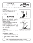
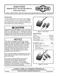
Df[\c;+(,. ()'M&)+'M FE&F==JN@K:? @ejkilZk`feJ_\\k Phone #: (360) 734-3482 • Online Tech Support: [email protected] • Web: www.shopfox.biz @ekif[lZk`fe The Model D4157 features a recessed START button that can be disabled with a padlock. It is designed as a replacement for an existing machine switch with the same dimensions and technical specifications. Padlock Hole Jg\Z`]`ZXk`fej Rated Voltage ........................................ 120/240V Rated Horsepower/Current at 120V ............... 2HP/35A Rated Horsepower/Current at 240V ............... 3HP/20A Phase ........................................................Single Padlock Shaft Size .......................................... 3⁄16" Figure 1. D4157 ON/OFF Switch. To reduce risk of serious burns, electrocution or death when installing this switch: • Only use this switch to replace an existing machine switch that has the same physical configuration and equivalent electrical specifications/ratings. • Installation must only be performed by an electrician or qualified service personnel, and all applicable electrical codes must be adhered to. • Turn OFF and completely disconnect all power sources to the machine before installing the switch. • Do not use this switch in wet or damp locations, or near explosive fumes or flammable liquids. It is not sealed or rated for these environments. • Make sure there is a verified machine ground on the circuit this switch is installed. 8DENG><=IH:EI:B7:G!'%&'7NLDD9HID8@>CI:GC6I>DC6A!>C8# &*(+'HI L6GC>C</CDEDGI>DCD;I=>HB6CJ6AB6N7:G:EGD9J8:9>C6CNH=6E:DG;DGBL>I=DJI I=:LG>II:C6EEGDK6AD;LDD9HID8@>CI:GC6I>DC6A!>C8# Eg^ciZY^c8]^cV Df[\c;+(,.@ejkilZk`fej @ejkXccXk`fe When installing the D4157 switch, use the wiring diagram in Figure 2 to ensure proper wire connections. Machine Verified Ground* Out 120V Neutral or 240V Hot Hot Out This switch is intended to be connected to stranded wire with insulated crimp-type ring wire terminals. Load KEDU HY56 Rear View of Switch Line All crimps must be "pull-checked" to ensure that wires are securely crimped and will not fall out with moderate tension or when exposed to normal machine vibration. Hot In In 120V Neutral or 240V Hot Power Source *The machine MUST be connected to a verified ground. In the event of certain malfunctions or breakdowns, grounding reduces the risk of electric shock by providing a path of least resistance for electric current. Figure 2. D4157 wiring diagram. ;`jXYc`e^CfZb`e^Jn`kZ_ GX[cfZb The ON/OFF switch can be disabled and locked by inserting a padlock through the ON button, as shown. Locking the switch in this manner can prevent unauthorized operation of the machine, which is especially important if the machine is not stored inside an access-restricted building. IMPORTANT: Locking the switch with a padlock only restricts its function. It is not a substitute for disconnecting power from the machine when adjusting or servicing. J_X]k Figure 3. Switch disabled by a padlock. NOTICE Children and untrained people can be seriously injured by this machine. This risk increases with unsupervised operation. To help prevent unsupervised operation, disable and lock the switch before leaving machine unattended! Place key in a well-hidden or secure location. The padlock shaft diameter is important to the disabling function of the switch. With any padlock used to lock the switch, test the switch after installation to ensure that it is properly disabled. Shaft Diameter Figure 4. Minimum lock shaft requirements. -2-